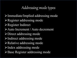
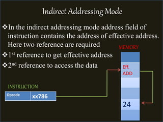
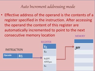
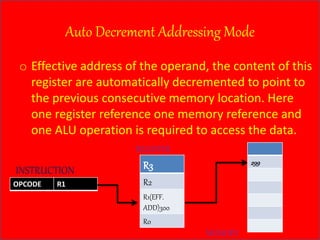
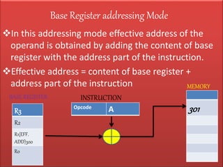
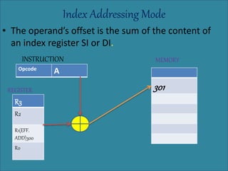
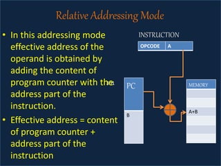
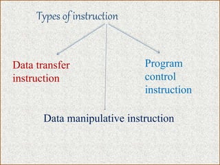
The document discusses various types of processor instructions, including zero, one, two, and three address instructions, explaining their formats and the use of operand addressing modes. It details how each type operates, including examples and differences in addressing modes such as direct, indirect, and relative addressing. Additionally, types of instructions are categorized into data transfer, data manipulation, and program control.

![Ex. X=(A+B)*(C+D)
PUSH A M[SP] A
PUSH B M[SP] B
ADD M[SP] A+B
PUSH C M[SP] C
PUSH D M[SP] D
ADD M[SP] C+D
MUL M[SP] (A+B)*(C+D)
POP X M[X] M[SP]](https://image.slidesharecdn.com/instructionformatujjwalmatoliya-230616070104-89249068/85/Instruction-format-UJJWAL-MATOLIYA-pptx-5-320.jpg)
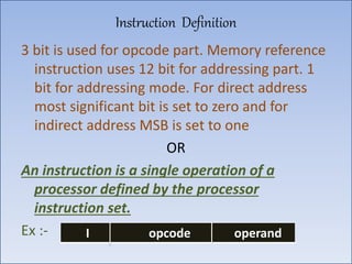
![EX. X=(A+B)*(C+D)
LOAD A // AC M[A]
ADD B // AC AC+M[B]
STORE T // M[T] AC
LOAD C // AC M[C]
ADD D // AC AC+M[D]
MUL T // AC AC*M[T]](https://image.slidesharecdn.com/instructionformatujjwalmatoliya-230616070104-89249068/85/Instruction-format-UJJWAL-MATOLIYA-pptx-7-320.jpg)
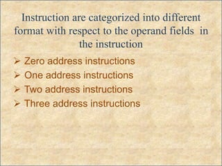
![EX. X=(A+B)*(C+D)
MOV R0 M[A]
MOV R1 M[B]
ADD R0 R1
MOV R2 M[C]
MOV R3 M[D]
ADD R2 R3
MUL R0 R2
STORE M[X] R3](https://image.slidesharecdn.com/instructionformatujjwalmatoliya-230616070104-89249068/85/Instruction-format-UJJWAL-MATOLIYA-pptx-9-320.jpg)
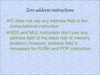
![EX. X= (A+B)*(C+D)
ADD R0 A B
ADD R1 C D
MUL M[X] R0 R1](https://image.slidesharecdn.com/instructionformatujjwalmatoliya-230616070104-89249068/85/Instruction-format-UJJWAL-MATOLIYA-pptx-11-320.jpg)