Downloaded 3,074 times


![2
1
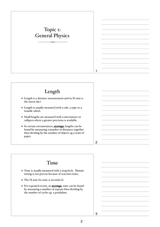
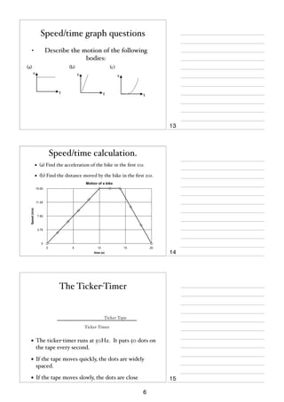
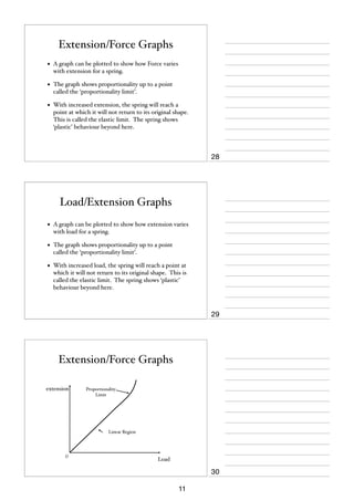
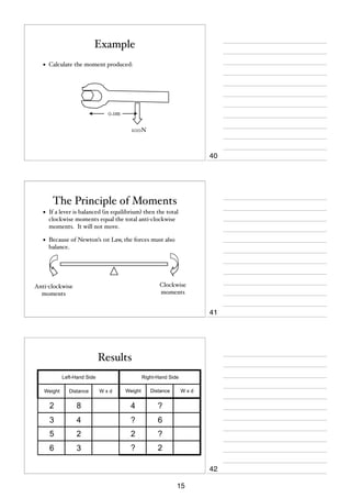
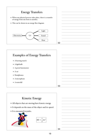
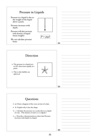
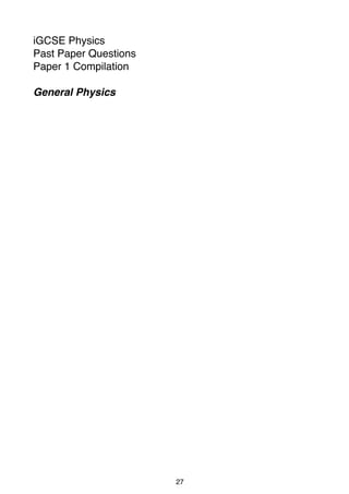
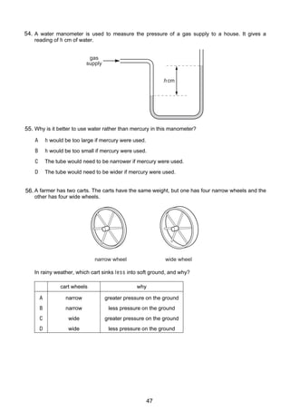
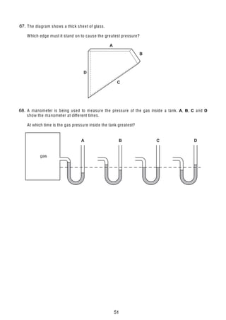
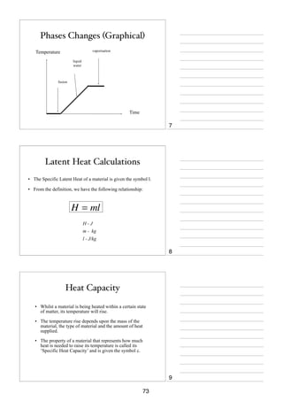
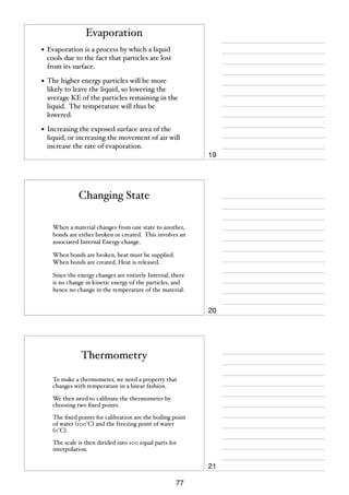
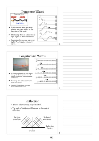
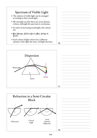
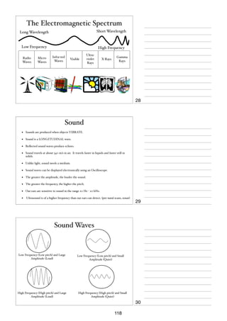
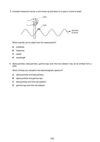
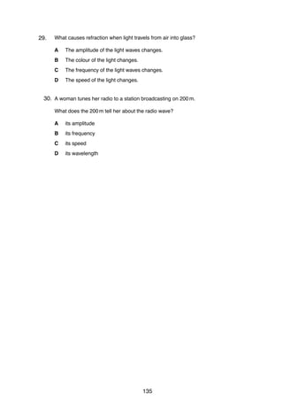
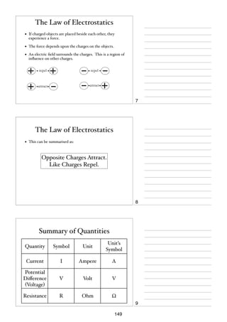
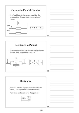
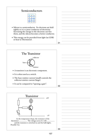
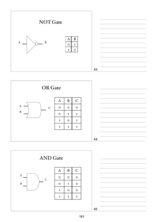
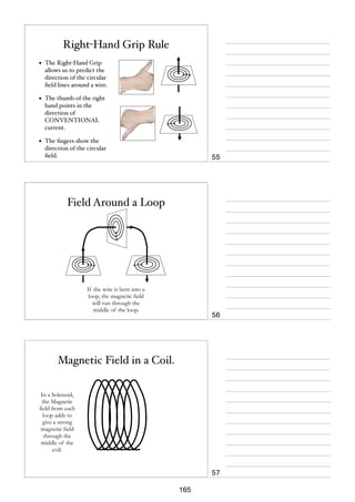
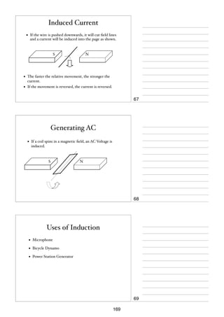
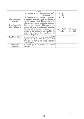
1. A group of students attempts to find out how much power each student can generate. The
students work in pairs in order to find the time taken for each student to run up a flight of
stairs.
The stairs used are shown in Fig. 1.1.
finishing point
starting point
Fig. 1.1
(a) Make a list of all the readings that would be needed. Where possible, indicate how the
accuracy of the readings could be improved.
..........................................................................................................................................
..........................................................................................................................................
..........................................................................................................................................
..........................................................................................................................................
..........................................................................................................................................
..................................................................................................................................... [4]
(b) Using words, not symbols, write down all equations that would be needed to work out
the power of a student.
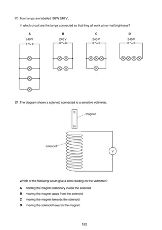
..........................................................................................................................................
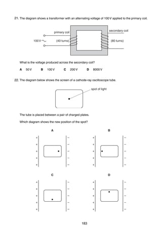
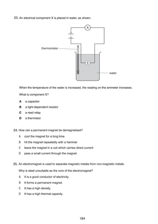
..........................................................................................................................................
..................................................................................................................................... [2]
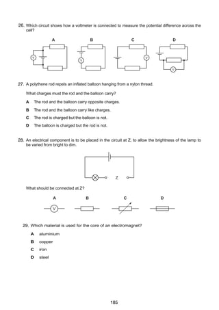
(c) (i)
When the student has reached the finishing point and is standing at the top of the
stairs, what form of energy has increased to its maximum?
...................................................................................................................................
(ii)
Suggest why the total power of the student is greater than the power calculated by
this method.
...................................................................................................................................
...................................................................................................................................
[3]
0625/3/M/J/02
53
For
Examiner’s
Use](https://image.slidesharecdn.com/igcsenotesnumbered-140205153241-phpapp01/85/IGCSE-Physics-notes-55-320.jpg)
![3
For
Examiner’s
Use
2
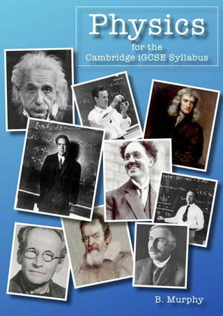
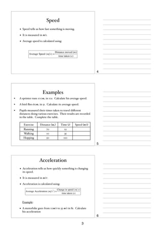
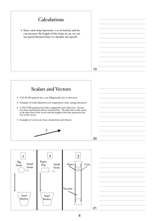
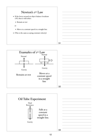
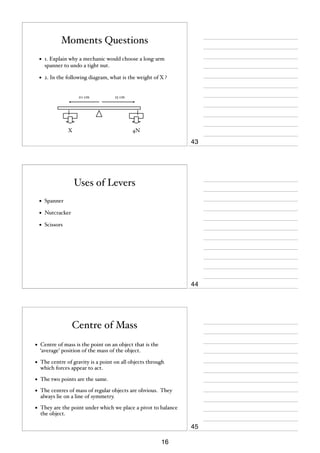
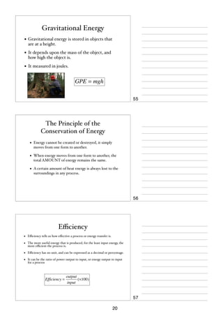
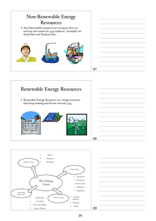
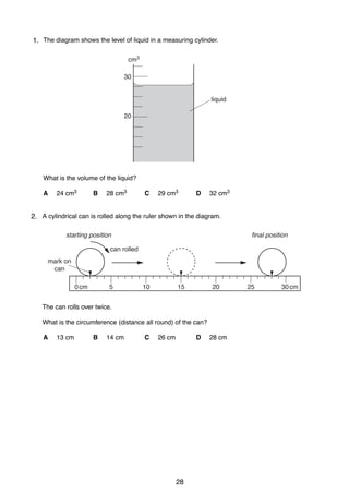
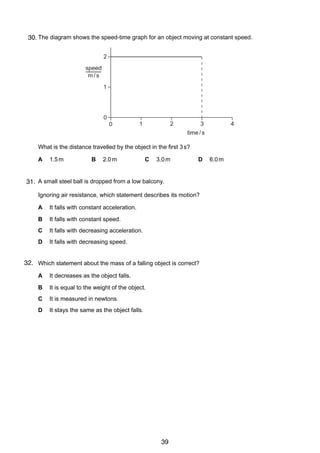
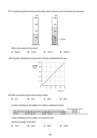
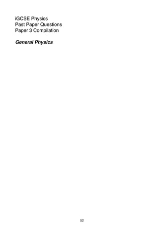
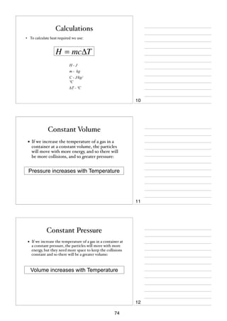
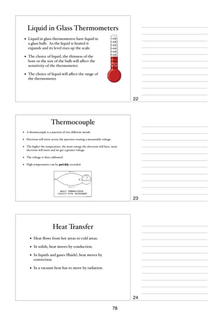
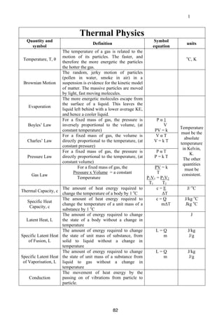
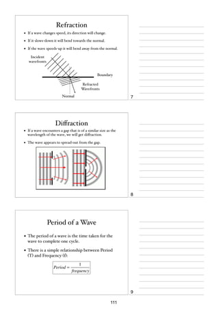
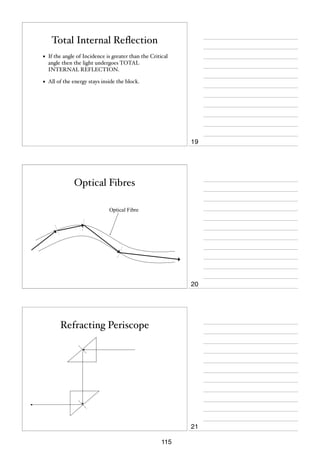
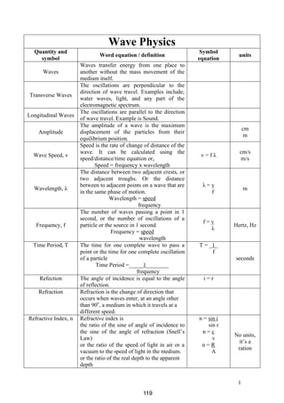
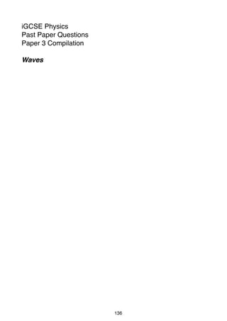
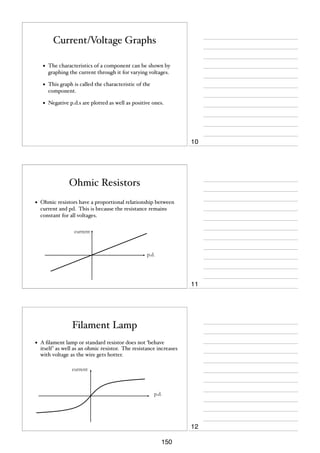
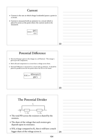
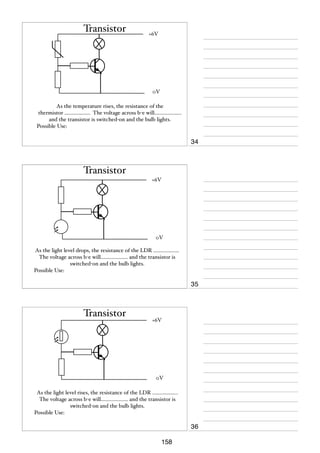
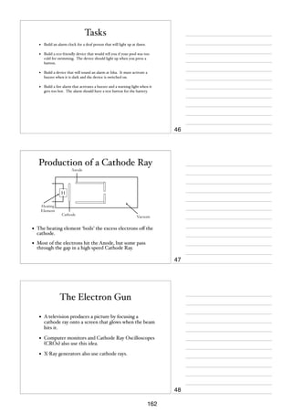
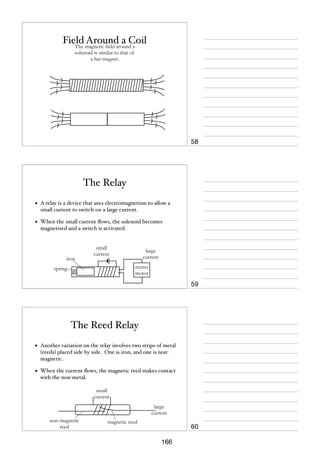
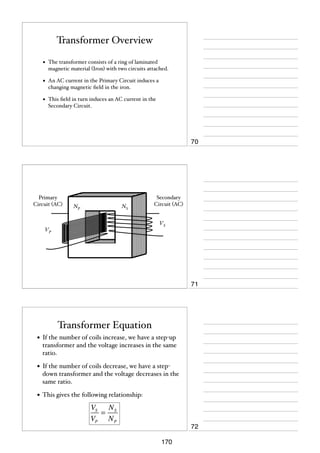
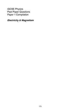
2. A small rubber ball falls vertically, hits the ground and rebounds vertically upwards.
Fig. 2.1 is the speed-time graph for the ball.
10
B
speed
8
m/s
6
D
4
2
0
A
0
E
C
0.5
1.0
1.5
time / s
2.0
Fig. 2.1
(a) Using information from the graph, describe the following parts of the motion of the ball.
(i)
part AB
...................................................................................................................................
...................................................................................................................................
...................................................................................................................................
(ii)
part DE
...................................................................................................................................
...................................................................................................................................
...................................................................................................................................
[3]
(b) Explain what is happening to the ball along the part of the graph from B through C to D.
..........................................................................................................................................
..........................................................................................................................................
..................................................................................................................................... [2]
(c) Whilst the ball is in contact with the ground, what is the
(i)
overall change in speed,
change in speed = ........................................
(ii)
overall change in velocity?
change in velocity = ......................................
[2]
0625/3/M/J/02
54
[Turn over](https://image.slidesharecdn.com/igcsenotesnumbered-140205153241-phpapp01/85/IGCSE-Physics-notes-56-320.jpg)
![4
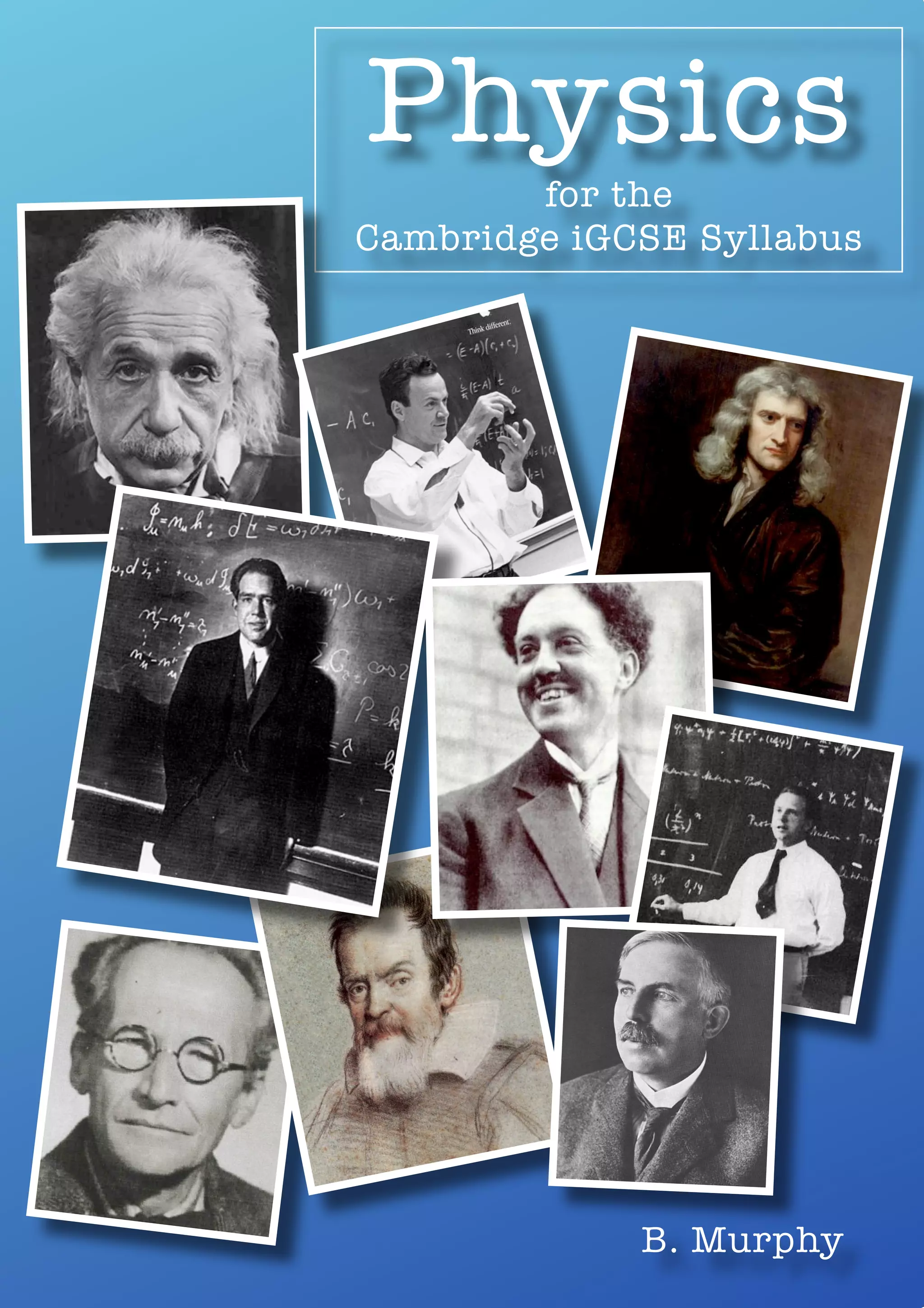
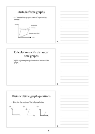
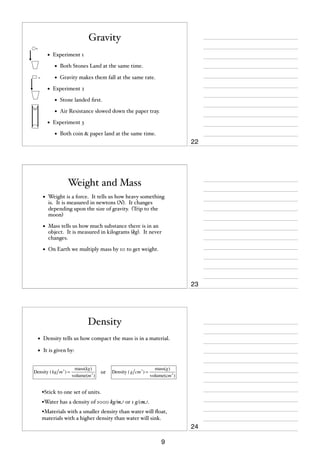
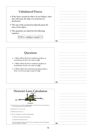
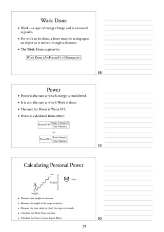
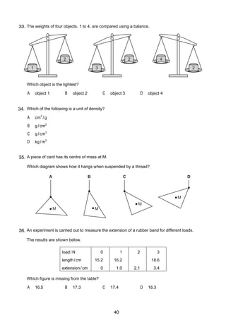
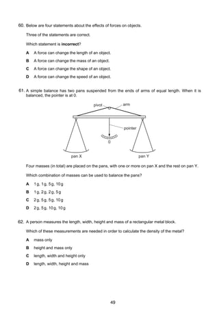
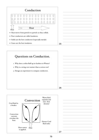
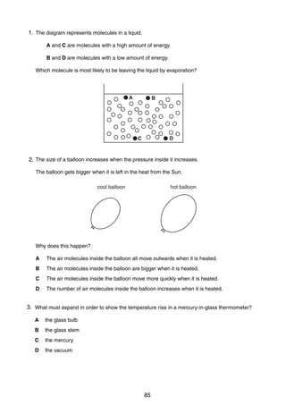
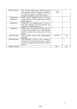
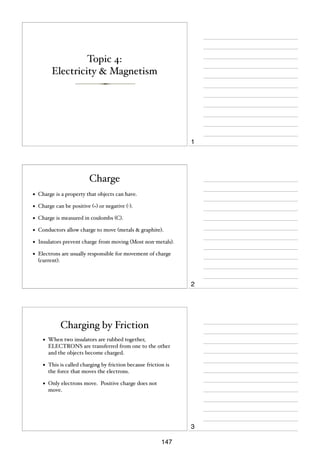
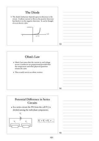
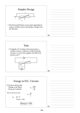
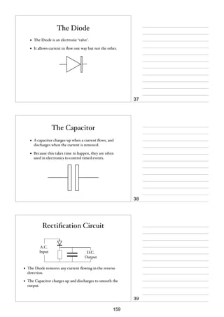
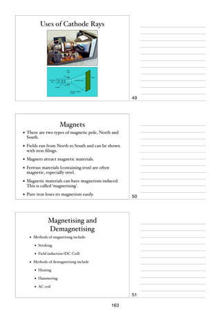
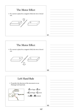
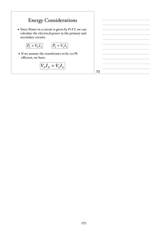
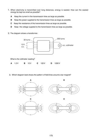
(d) Use your answer to (c) to explain the difference between speed and velocity.
..........................................................................................................................................
..........................................................................................................................................
..................................................................................................................................... [2]
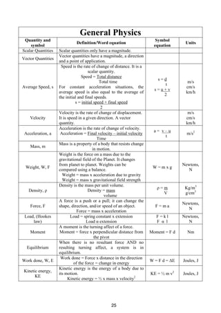
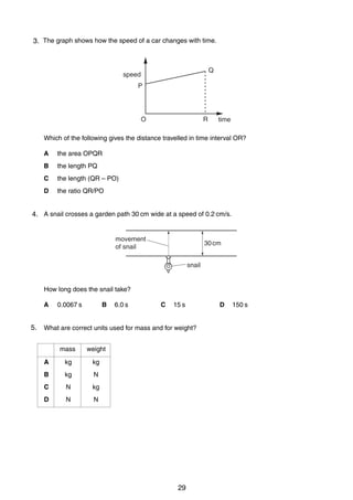
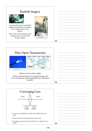
(e) Use the graph to calculate the distance travelled by the ball between D and E.
distance travelled = ..................................[2]
(f)
Use the graph to calculate the deceleration of the ball between D and E.
deceleration = ..................................[2]
0625/3/M/J/02
55
For
Examiner’s
Use](https://image.slidesharecdn.com/igcsenotesnumbered-140205153241-phpapp01/85/IGCSE-Physics-notes-57-320.jpg)
![2
1
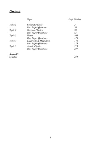
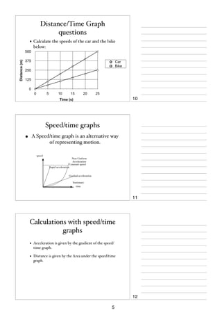
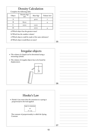
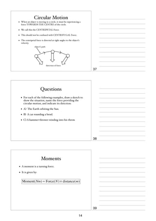
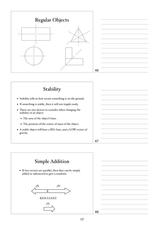
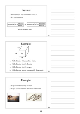
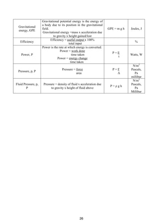
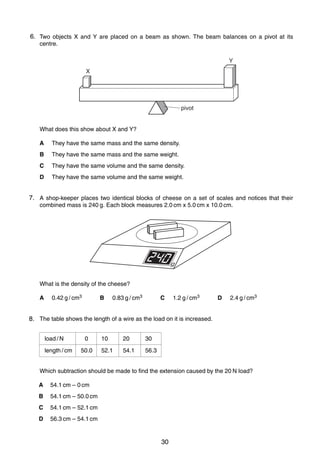
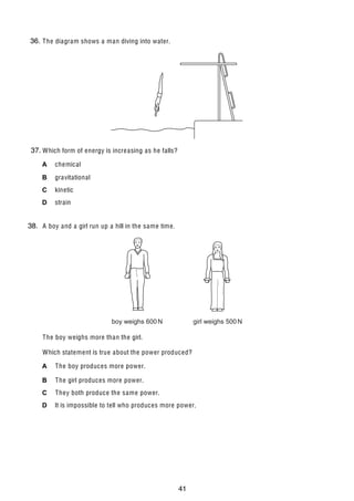
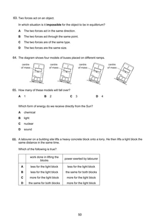
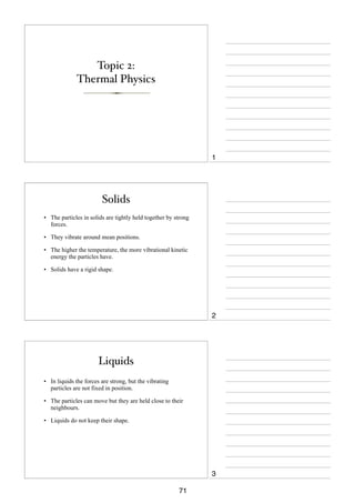
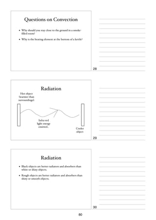
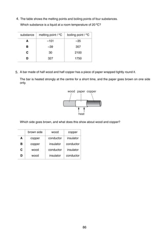
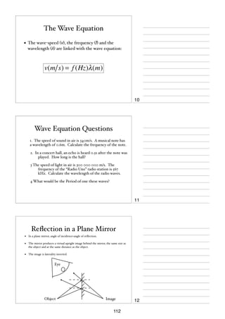
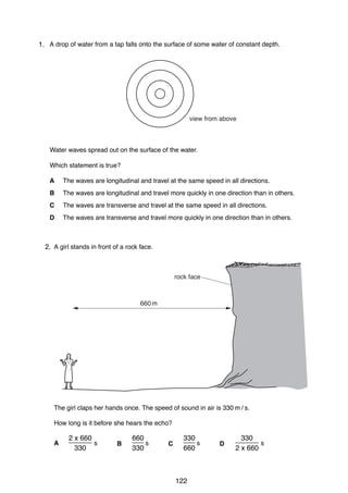
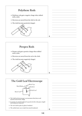
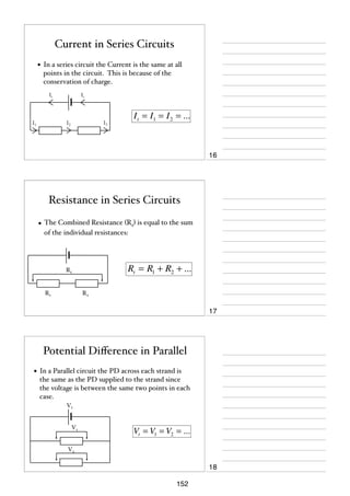
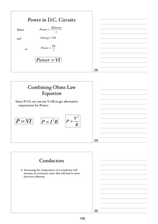
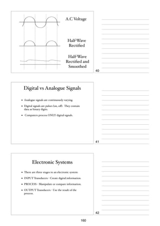
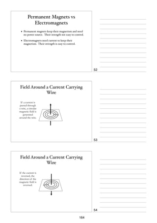
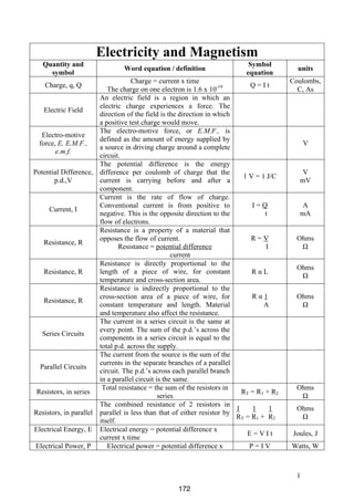
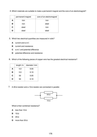
3. Fig. 1.1 shows apparatus that may be used to compare the strengths of two springs of the
same size, but made from different materials.
spring
scale
masses
Fig. 1.1
(a) (i)
Explain how the masses produce a force to stretch the spring.
...................................................................................................................................
(ii) Explain why this force, like all forces, is a vector quantity.
...................................................................................................................................
...................................................................................................................................
[2]
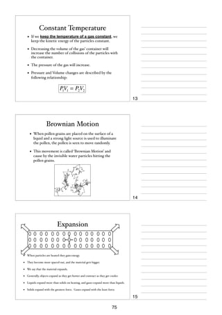
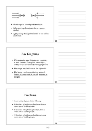
(b) Fig. 1.2 shows the graphs obtained when the two springs are stretched.
force/N
20
spring 1
15
spring 2
10
5
0
0
10
20
30
extension/mm
Fig. 1.2
0625/3/M/J/03
56
40
For
Examiner’s
Use](https://image.slidesharecdn.com/igcsenotesnumbered-140205153241-phpapp01/85/IGCSE-Physics-notes-58-320.jpg)
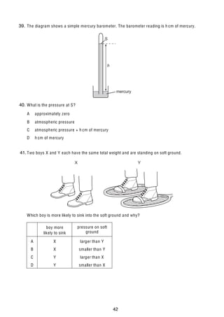
![3
(i)
State which spring is more difficult to extend. Quote values from the graphs to
support your answer.
For
Examiner’s
Use
...................................................................................................................................
...................................................................................................................................
...................................................................................................................................
...................................................................................................................................
(ii)
On the graph of spring 2, mark a point P at the limit of proportionality. Explain your
choice of point P.
...................................................................................................................................
...................................................................................................................................
...................................................................................................................................
(iii)
Use the graphs to find the difference in the extensions of the two springs when a
force of 15 N is applied to each one.
difference in extensions = ..................................
[6]
24. The speed of a cyclist reduces uniformly from 2.5 m/s to 1.0 m/s in 12 s.
(a) Calculate the deceleration of the cyclist.
deceleration = ..................................[3]
(b) Calculate the distance travelled by the cyclist in this time.
distance = ..................................[2]
0625/3/M/J/03
57
[Turn over](https://image.slidesharecdn.com/igcsenotesnumbered-140205153241-phpapp01/85/IGCSE-Physics-notes-59-320.jpg)
![4
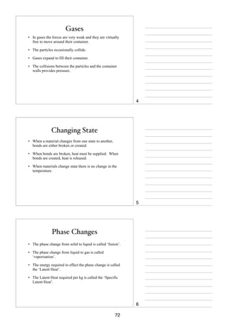
3
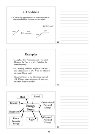
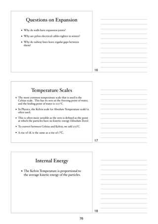
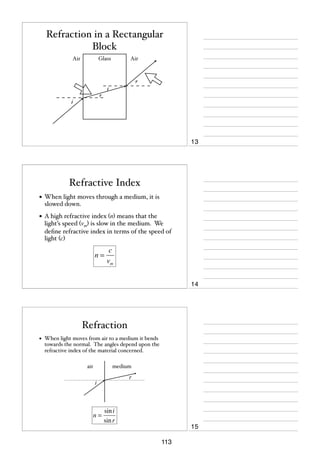
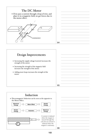
5. Fig. 3.1 shows the arm of a crane when it is lifting a heavy box.
1220 N
950 N
40° 30°
P
box
Fig. 3.1
(a) By the use of a scale diagram (not calculation) of the forces acting at P, find the weight
of the box.
[5]
0625/3/M/J/03
58
For
Examiner’s
Use](https://image.slidesharecdn.com/igcsenotesnumbered-140205153241-phpapp01/85/IGCSE-Physics-notes-60-320.jpg)
![For
Examiner’s
Use
5
(b) Another box of weight 1500 N is raised vertically by 3.0 m.
(i)
Calculate the work done on the box.
work done = ..................................
(ii)
The crane takes 2.5 s to raise this box 3.0 m. Calculate the power output of the
crane.
power = ..................................
[4]
4
Fig. 4.1 shows a sealed glass syringe that contains air and many very tiny suspended dust
particles.
syringe
seal
piston
dust particles
Fig. 4.1
(a) Explain why the dust particles are suspended in the air and do not settle to the bottom.
..........................................................................................................................................
..........................................................................................................................................
..........................................................................................................................................
......................................................................................................................................[3]
(b) The air in the syringe is at a pressure of 2.0 × 10⁵ Pa. The piston is slowly moved into the
syringe, keeping the temperature constant, until the volume of the air is reduced from
80 cm3 to 25 cm3. Calculate the final pressure of the air.
pressure = ..................................[3]
0625/3/M/J/03
59
[Turn over](https://image.slidesharecdn.com/igcsenotesnumbered-140205153241-phpapp01/85/IGCSE-Physics-notes-61-320.jpg)
![2
For
Examiner’s
Use
6. Fig. 1.1 shows a cycle track.
1
A
B
E
C
v = 6 m/s
D
Fig. 1.1
A cyclist starts at A and follows the path ABCDEB.
The speed-time graph is shown in Fig. 1.2.
B
C
D
E
B
6
speed
m/s 5
4
3
2
1
0A
0
10
20
30
40
50
60
70
80
90
100
time / s
Fig. 1.2
(a) Use information from Fig. 1.1 and Fig. 1.2 to describe the motion of the cyclist
(i)
along AB,
...................................................................................................................................
(ii)
along BCDEB.
...................................................................................................................................
...................................................................................................................................
[4]
© UCLES 2004
0625/03 M/J/04
60](https://image.slidesharecdn.com/igcsenotesnumbered-140205153241-phpapp01/85/IGCSE-Physics-notes-62-320.jpg)
![3
For
Examiner’s
Use
(b) The velocity v of the cyclist at C is shown in Fig. 1.1.
State one similarity and one difference between the velocity at C and the velocity at E.
similarity ...........................................................................................................................
difference ......................................................................................................................[2]
(c) Calculate
(i)
the distance along the cycle track from A to B,
distance = …………………
(ii)
the circumference of the circular part of the track.
circumference = …………………
[4]
© UCLES 2004
0625/03 M/J/04
61
[Turn over](https://image.slidesharecdn.com/igcsenotesnumbered-140205153241-phpapp01/85/IGCSE-Physics-notes-63-320.jpg)
![4
7. Fig. 2.1 shows a rock that is falling from the top of a cliff into the river below.
2
cliff
falling
rock
river
Fig. 2.1
(a) The mass of the rock is 75 kg. The acceleration of free fall is 10 m/s2.
Calculate the weight of the rock.
weight = …………………[1]
(b) The rock falls from rest through a distance of 15 m before it hits the water.
Calculate its kinetic energy just before hitting the water. Show your working.
kinetic energy = …………………[3]
(c) The rock hits the water. Suggest what happens to the kinetic energy of the rock during
the impact.
..........................................................................................................................................
..........................................................................................................................................
......................................................................................................................................[3]
© UCLES 2004
0625/03 M/J/04
62
For
Examiner’s
Use](https://image.slidesharecdn.com/igcsenotesnumbered-140205153241-phpapp01/85/IGCSE-Physics-notes-64-320.jpg)
![5
For
Examiner’s
Use
8. A large spring is repeatedly stretched by an athlete to increase the strength of his arms.
3
Fig. 3.1 is a table showing the force required to stretch the spring.
extension of spring / m
force exerted to produce extension / N
0.096
0.192
0.288
0.384
250
500
750
1000
Fig. 3.1
(a) (i)
State Hooke’s law.
...................................................................................................................................
...............................................................................................................................[1]
(ii)
Use the results in Fig. 3.1 to show that the spring obeys Hooke’s law.
[1]
(b) Another athlete using a different spring exerts an average force of 400 N to enable her
to extend the spring by 0.210 m.
(i)
Calculate the work done by this athlete in extending the spring once.
work done = …………………
(ii)
She is able to extend the spring by this amount and to release it 24 times in 60 s.
Calculate the power used by this athlete while doing this exercise.
power = …………………
[4]
© UCLES 2004
0625/03 M/J/04
63
[Turn over](https://image.slidesharecdn.com/igcsenotesnumbered-140205153241-phpapp01/85/IGCSE-Physics-notes-65-320.jpg)
![2
9. A solid plastic sphere falls towards the Earth.
1
Fig. 1.1 is the speed-time graph of the fall up to the point where the sphere hits the Earth’s
surface.
140
speed
m/s
R
120
S
T
100
80
60
Q
40
20
0
P
0
10
20
30
40
50
60
70 80
time / s
90
100 110
Fig. 1.1
(a) Describe in detail the motion of the sphere shown by the graph.
..........................................................................................................................................
..........................................................................................................................................
..........................................................................................................................................
..........................................................................................................................................
..................................................................................................................................... [3]
© UCLES 2005
0625/03/M/J/05
64
For
Examiner’s
Use](https://image.slidesharecdn.com/igcsenotesnumbered-140205153241-phpapp01/85/IGCSE-Physics-notes-66-320.jpg)
![3
(b) On Fig. 1.2, draw arrows to show the directions of the forces acting on the sphere when
it is at the position shown by point S on the graph. Label your arrows with the names of
the forces.
[2]
Fig. 1.2
(c) Explain why the sphere is moving with constant speed at S.
..........................................................................................................................................
..........................................................................................................................................
..................................................................................................................................... [2]
(d) Use the graph to calculate the approximate distance that the sphere falls
(i)
between R and T,
(ii)
between P and Q.
distance = ………………. [2]
distance = ………………. [2]
© UCLES 2005
0625/03/M/J/05
65
[Turn over
For
Examiner’s
Use](https://image.slidesharecdn.com/igcsenotesnumbered-140205153241-phpapp01/85/IGCSE-Physics-notes-67-320.jpg)
![4
10. Fig. 2.1 shows a simple pendulum that swings backwards and forwards between P and Q.
2
support
string
P
R
Q
pendulum bob
Fig. 2.1
(a) The time taken for the pendulum to swing from P to Q is approximately 0.5 s.
Describe how you would determine this time as accurately as possible.
..........................................................................................................................................
..........................................................................................................................................
..................................................................................................................................... [2]
(b) (i)
State the two vertical forces acting on the pendulum bob when it is at position R.
1. ...............................................................................................................................
2. .......................................................................................................................... [1]
(ii)
The pendulum bob moves along the arc of a circle. State the direction of the
resultant of the two forces in (i).
.............................................................................................................................. [1]
(c) The mass of the bob is 0.2 kg. During the swing it moves so that P is 0.05 m higher
than R.
Calculate the increase in potential energy of the pendulum bob between R and P.
potential energy = ………………. [2]
© UCLES 2005
0625/03/M/J/05
66
For
Examiner’s
Use](https://image.slidesharecdn.com/igcsenotesnumbered-140205153241-phpapp01/85/IGCSE-Physics-notes-68-320.jpg)
![5
11. A mass of 3.0 kg accelerates at 2.0 m/s2 in a straight line.
3
(a) State why the velocity and the acceleration are both described as vector quantities.
..........................................................................................................................................
..................................................................................................................................... [1]
(b) Calculate the force required to accelerate the mass.
force = ………………. [2]
(c) The mass hits a wall.
The average force exerted on the wall during the impact is 120 N.
The area of the mass in contact with the wall at impact is 0.050 m2.
Calculate the average pressure that the mass exerts on the wall during the impact.
pressure = ………………. [2]
© UCLES 2005
0625/03/M/J/05
67
[Turn over
For
Examiner’s
Use](https://image.slidesharecdn.com/igcsenotesnumbered-140205153241-phpapp01/85/IGCSE-Physics-notes-69-320.jpg)
![2
1
12. A bus travels from one bus stop to the next. The journey has three distinct parts. Stated in
order they are
uniform acceleration from rest for 8.0 s,
uniform speed for 12 s,
non-uniform deceleration for 5.0 s.
Fig. 1.1 shows only the deceleration of the bus.
15
speed
m/s
10
5
0
0
5
10
15
time/s
20
25
Fig. 1.1
(a) On Fig. 1.1, complete the graph to show the first two parts of the journey.
[3]
(b) Calculate the acceleration of the bus 4.0 s after leaving the first bus stop.
acceleration = ........................[2]
(c) Use the graph to estimate the distance the bus travels between 20 s and 25 s.
estimated distance = ........................[2]
(d) On leaving the second bus stop, the uniform acceleration of the bus is 1.2 m / s2. The
mass of the bus and passengers is 4000 kg.
Calculate the accelerating force that acts on the bus.
force = ........................[2]
(e) The acceleration of the bus from the second bus stop is less than that from the first bus
stop.
Suggest two reasons for this.
1. ......................................................................................................................................
..........................................................................................................................................
2. ......................................................................................................................................
......................................................................................................................................[2]
© UCLES 2006
0625/03/M/J/06
68
For
Examiner’s
Use](https://image.slidesharecdn.com/igcsenotesnumbered-140205153241-phpapp01/85/IGCSE-Physics-notes-70-320.jpg)
![3
2
13. A student sets up the apparatus shown in Fig. 2.1 in order to find the resultant of the two
tensions T1 and T2 acting at P. When the tensions T1, T2 and T3 are balanced, the angles
between T1 and the vertical and T2 and the vertical are as marked on Fig. 2.1.
pulley
pulley
T1 = 6.0 N
69°
T2 = 8.0 N
44°
vertical
board
P
T3
Fig. 2.1
In the space below, draw a scale diagram of the forces T1 and T2. Use the diagram to find the
resultant of the two forces.
State
(a) the scale used,
scale = ........................................
(b) the value of the resultant,
value = ........................................
(c) the direction of the resultant.
© UCLES 2006
direction = ........................................
[6]
0625/03/M/J/06
69
[Turn over
For
Examiner’s
Use](https://image.slidesharecdn.com/igcsenotesnumbered-140205153241-phpapp01/85/IGCSE-Physics-notes-71-320.jpg)
![4
3
14. An electric pump is used to raise water from a well, as shown in Fig. 3.1.
pump
ground
well
Fig. 3.1
(a) The pump does work in raising the water. State an equation that could be used to
calculate the work done in raising the water.
......................................................................................................................................[2]
(b) The water is raised through a vertical distance of 8.0 m. The weight of water raised in
5.0 s is 100 N.
(i)
Calculate the work done in raising the water in this time.
work done = .......................[1]
(ii)
Calculate the power the pump uses to raise the water.
power = ........................[1]
(iii)
The energy transferred by the pump to the water is greater than your answer to (i).
Suggest what the additional energy is used for.
..............................................................................................................................[1]
© UCLES 2006
0625/03/M/J/06
70
For
Examiner’s
Use](https://image.slidesharecdn.com/igcsenotesnumbered-140205153241-phpapp01/85/IGCSE-Physics-notes-72-320.jpg)


![5
3
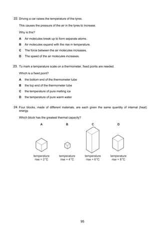
1.
Fig. 3.1 is an attempt to show the molecules in water and the water vapour molecules over
the water surface.
For
Examiner’s
Use
water vapour
molecules
water molecules
Fig. 3.1
(a) Explain, in terms of the energies of the molecules, why only a few water molecules have
escaped from the water surface.
..........................................................................................................................................
..........................................................................................................................................
..................................................................................................................................... [2]
(b) State two ways of increasing the number of water molecules escaping from the surface.
1 .......................................................................................................................................
2 .................................................................................................................................. [2]
(c) Energy is required to evaporate water.
Explain, in molecular terms, why this energy is needed.
..........................................................................................................................................
..........................................................................................................................................
..................................................................................................................................... [2]
0625/3/M/J/02
98
[Turn over](https://image.slidesharecdn.com/igcsenotesnumbered-140205153241-phpapp01/85/IGCSE-Physics-notes-100-320.jpg)
![6
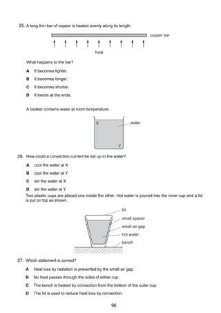
42. (a) Fig. 4.1 shows a cylinder containing air at a pressure of 1.0 × 10⁵ Pa. The length of the
air column in the cylinder is 80 mm.
80 mm
air
piston
cylinder
Fig. 4.1
The piston is pushed in until the pressure in the cylinder rises to 3.8 × 10⁵ Pa.
Calculate the new length of the air column in the cylinder, assuming that the
temperature of the air has not changed.
new length = .................................. [3]
(b) Fig. 4.2 shows the same cylinder containing air.
air
Fig. 4.2
The volume of the air in the cylinder changes as the temperature of the air changes.
(i)
The apparatus is to be used as a thermometer. Describe how two fixed points, 0 °C
and 100 °C, and a temperature scale could be marked on the apparatus.
...................................................................................................................................
...................................................................................................................................
...................................................................................................................................
...................................................................................................................................
(ii)
Describe how this apparatus could be used to indicate the temperature of a large
beaker of water.
...................................................................................................................................
...................................................................................................................................
...................................................................................................................................
...................................................................................................................................
[5]
0625/3/M/J/02
99
For
Examiner’s
Use](https://image.slidesharecdn.com/igcsenotesnumbered-140205153241-phpapp01/85/IGCSE-Physics-notes-101-320.jpg)
![[4]
4
Fig. 4.1 shows a sealed glass syringe that contains air and many very tiny suspended dust
5
particles.
3. (b) Another box of weight 1500 N is raised vertically by 3.0 m.
(i)
syringe
Calculate the work done on the box.
seal
piston
work done = ..................................
dust particles
(ii)
For
Examiner’s
Use
The crane takes 2.5 s to raise this box 3.0 m. Calculate the power output of the
Fig. 4.1
crane.
(a) Explain why the dust particles are suspended in the air and do not settle to the bottom.
..........................................................................................................................................
..........................................................................................................................................
power = ..................................
[4]
..........................................................................................................................................
4
......................................................................................................................................[3]
Fig. 4.1 shows a sealed glass syringe that contains air and many very tiny suspended dust
particles.
(b) The air in the syringe is at a pressure of 2.0 × 10⁵ Pa. The piston is slowly moved into the
syringe, keeping the temperature constant, until the volume of the air is reduced from
syringe
80 cm3 to 25 cm3. Calculate the final pressure of the air.
seal
piston
pressure = ..................................[3]
dust particles
0625/3/M/J/03
Fig. 4.1
[Turn over
(a) Explain why the dust particles are suspended in the air and do not settle to the bottom.
..........................................................................................................................................
..........................................................................................................................................
..........................................................................................................................................
......................................................................................................................................[3]
(b) The air in the syringe is at a pressure of 2.0 × 10⁵ Pa. The piston is slowly moved into the
syringe, keeping the temperature constant, until the volume of the air is reduced from
80 cm3 to 25 cm3. Calculate the final pressure of the air.
pressure = ..................................[3]
0625/3/M/J/03
100
[Turn over](https://image.slidesharecdn.com/igcsenotesnumbered-140205153241-phpapp01/85/IGCSE-Physics-notes-102-320.jpg)
![6
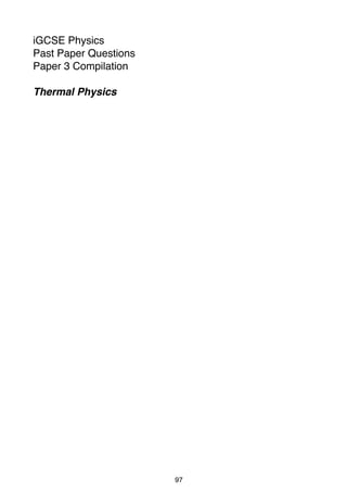
54. Fig. 5.1 shows a thermocouple set up to measure the temperature at a point on a solar
panel.
Sun's rays
surface
of solar
panel
Z
X
cold junction
Y
hot junction
Fig. 5.1
(a) X is a copper wire.
(i)
Suggest a material for Y.
...................................................................................................................................
(ii)
Name the component Z.
...................................................................................................................................
[2]
(b) Explain how a thermocouple is used to measure temperature.
..........................................................................................................................................
..........................................................................................................................................
......................................................................................................................................[3]
(c) Experiment shows that the temperature of the surface depends upon the type of
surface used.
Describe the nature of the surface that will cause the temperature to rise most.
..........................................................................................................................................
......................................................................................................................................[1]
0625/3/M/J/03
101
For
Examiner’s
Use](https://image.slidesharecdn.com/igcsenotesnumbered-140205153241-phpapp01/85/IGCSE-Physics-notes-103-320.jpg)
![6
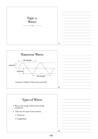
5. (a) Two identical open boxes originally contain the same volume of water.
4
One is kept at 15 °C and the other at 85 °C for the same length of time.
Fig. 4.1 shows the final water levels.
15 °C
85 °C
Fig. 4.1
With reference to the energies of the water molecules, explain why the levels are
different.
..........................................................................................................................................
..........................................................................................................................................
..........................................................................................................................................
......................................................................................................................................[3]
(b) In an experiment to find the specific latent heat of vaporisation of water, it took 34 500 J
of energy to evaporate 15 g of water that was originally at 100 °C.
A second experiment showed that 600 J of energy was lost to the atmosphere from the
apparatus during the time it took to evaporate 15 g of water.
Calculate the specific latent heat of vaporisation of water that would be obtained from
this experiment.
specific latent heat = …………………[3]
© UCLES 2004
0625/03 M/J/04
102
For
Examiner’s
Use](https://image.slidesharecdn.com/igcsenotesnumbered-140205153241-phpapp01/85/IGCSE-Physics-notes-104-320.jpg)
![7
56. (a) Fig. 5.1 shows two identical metal plates. The front surface of one is dull black and the
front surface of the other is shiny silver.
The plates are fitted with heaters that keep the surfaces of the plates at the same
temperature.
dull black
For
Examiner’s
Use
shiny silver
Fig. 5.1
(i)
State the additional apparatus needed to test which surface is the best emitter of
heat radiation.
...................................................................................................................................
(ii)
State one precaution that is needed to ensure a fair comparison.
...................................................................................................................................
...................................................................................................................................
(iii)
State the result that you expect.
...................................................................................................................................
(iv)
Write down another name for heat radiation.
...................................................................................................................................
[4]
(b) In the space below, draw a labelled diagram of an everyday situation in which a
convection current occurs.
Mark the path of the current with a line and show its direction with arrows.
© UCLES 2004
0625/03 M/J/04
103
[3]
[Turn over](https://image.slidesharecdn.com/igcsenotesnumbered-140205153241-phpapp01/85/IGCSE-Physics-notes-105-320.jpg)
![6
7.
4
Fig. 4.1 shows apparatus that a student uses to make an estimate of the specific heat
capacity of iron.
electrical heater
thermometer
iron block
Fig. 4.1
(a) The power of the heater is known. State the four readings the student must take to find
the specific heat capacity of iron.
1. ......................................................................................................................................
2. ......................................................................................................................................
3. ......................................................................................................................................
4. ................................................................................................................................. [3]
(b) Write down an equation, in words or in symbols, that could be used to work out the
specific heat capacity of iron from the readings in (a).
[2]
© UCLES 2005
0625/03/M/J/05
104
For
Examiner’s
Use](https://image.slidesharecdn.com/igcsenotesnumbered-140205153241-phpapp01/85/IGCSE-Physics-notes-106-320.jpg)
![7
(c) (i)
Explain why the value obtained with this apparatus is higher than the actual value.
...................................................................................................................................
.............................................................................................................................. [1]
(ii)
State one addition to the apparatus that would help to improve the accuracy of the
value obtained.
...................................................................................................................................
.............................................................................................................................. [1]
© UCLES 2005
0625/03/M/J/05
105
[Turn over
For
Examiner’s
Use](https://image.slidesharecdn.com/igcsenotesnumbered-140205153241-phpapp01/85/IGCSE-Physics-notes-107-320.jpg)
![8
5 8. (a) Fig. 5.1 shows the paths of a few air molecules and a single dust particle. The actual air
molecules are too small to show on the diagram.
paths of
air molecules
dust particle
Fig. 5.1
Explain why the dust particle undergoes small random movements.
..........................................................................................................................................
..........................................................................................................................................
..........................................................................................................................................
..................................................................................................................................... [4]
(b) Fig. 5.2 shows the paths of a few molecules leaving the surface of a liquid. The liquid is
below its boiling point.
air and vapour
liquid
Fig. 5.2
(i)
State which liquid molecules are most likely to leave the surface.
...................................................................................................................................
.............................................................................................................................. [1]
(ii) Explain your answer to (i).
...................................................................................................................................
...................................................................................................................................
.............................................................................................................................. [2]
© UCLES 2005
0625/03/M/J/05
106
For
Examiner’s
Use](https://image.slidesharecdn.com/igcsenotesnumbered-140205153241-phpapp01/85/IGCSE-Physics-notes-108-320.jpg)
![5
4 9. (a) State two differences between evaporation of water and boiling of water.
1. ......................................................................................................................................
2. ..................................................................................................................................[2]
(b) The specific latent heat of vaporisation of water is 2260 kJ / kg.
Explain why this energy is needed to boil water and why the temperature of the water
does not change during the boiling.
..........................................................................................................................................
..........................................................................................................................................
..........................................................................................................................................
......................................................................................................................................[3]
(c) A laboratory determination of the specific latent heat of vaporisation of water uses a
120 W heater to keep water boiling at its boiling point. Water is turned into steam at the
rate of 0.050 g / s.
Calculate the value of the specific latent heat of vaporisation obtained from this
experiment. Show your working.
specific latent heat of vaporisation = ........................[3]
© UCLES 2006
0625/03/M/J/06
107
[Turn over
For
Examiner’s
Use](https://image.slidesharecdn.com/igcsenotesnumbered-140205153241-phpapp01/85/IGCSE-Physics-notes-109-320.jpg)
![6
510. (a) Fig. 5.1 shows a tank used for evaporating salt solution to produce crystals.
evaporating tank
steam in
salt solution
steam out
Fig. 5.1
Suggest two ways of increasing the rate of evaporation of the water from the solution.
Changes may be made to the apparatus, but the rate of steam supply must stay constant.
You may assume the temperature of the salt solution remains constant.
1. ......................................................................................................................................
..........................................................................................................................................
2. ......................................................................................................................................
......................................................................................................................................[2]
(b) A manufacturer of liquid-in-glass thermometers changes the design in order to meet
new requirements.
Describe the changes that could be made to
(i)
give the thermometer a greater range,
..............................................................................................................................[1]
(ii)
make the thermometer more sensitive.
..............................................................................................................................[1]
(c) A toilet flush is operated by the compression of air. The air inside the flush has a
pressure of 1.0 × 10⁵ Pa and a volume of 150 cm3. When the flush is operated the
volume is reduced to 50 cm3. The temperature of the air remains constant during this
process.
Calculate the new pressure of the air inside the flush.
pressure = .......................[2]
© UCLES 2006
0625/03/M/J/06
108
For
Examiner’s
Use](https://image.slidesharecdn.com/igcsenotesnumbered-140205153241-phpapp01/85/IGCSE-Physics-notes-110-320.jpg)

![7
5 1. Fig. 5.1 shows an arrangement where a plane mirror is used in a shop to watch a display
counter. The arrangement is drawn to a scale of 1 cm : 1 m.
For
Examiner’s
Use
plane mirror
P
wall
display counter
Fig. 5.1
(a) (i)
State the law of reflection.
...................................................................................................................................
(ii)
On Fig. 5.1, draw rays to show how much of the display cannot be seen from P.
Indicate this by shading in the part that cannot be seen.
[3]
(b) By construction on Fig. 5.1 and by using the scale, calculate how far the mirror must be
moved so that all of the display counter can be seen from P.
distance moved = .................................... [2]
(c) State the characteristics of an image seen in a plane mirror.
..........................................................................................................................................
..........................................................................................................................................
..................................................................................................................................... [2]
0625/3/M/J/02
137
[Turn over](https://image.slidesharecdn.com/igcsenotesnumbered-140205153241-phpapp01/85/IGCSE-Physics-notes-139-320.jpg)
![For
Examiner’s
Use
8
62. Observations of a distant thunderstorm are made.
(a) During a lightning flash, the average wavelength of the light emitted is 5 × 10⁻⁷ m. This
light travels at 3 × 10⁸ m/s.
Calculate the average frequency of this light.
frequency = ...................................... [2]
(b) The interval between the lightning flash being seen and the thunder being heard is
3.6 s. The speed of sound in air is 340 m/s.
(i)
Calculate the distance between the thunderstorm and the observer.
distance = ............................................
(ii)
Explain why the speed of light is not taken into account in this calculation.
...................................................................................................................................
...................................................................................................................................
[3]
(c) A single ray of white light from the lightning is incident on a prism as shown in Fig. 6.1.
prism
screen
ray of
light
Fig. 6.1
Complete the path of the ray to show how a spectrum is formed on the screen. Label the
colours.
[2]
0625/3/M/J/02
138](https://image.slidesharecdn.com/igcsenotesnumbered-140205153241-phpapp01/85/IGCSE-Physics-notes-140-320.jpg)
![7
For
Examiner’s
Use
63. Fig. 6.1 shows wavefronts of light crossing the edge of a glass block from air into glass.
air
direction in which
wavefronts
are moving
glass
edge of glass
Fig. 6.1
(a) On Fig. 6.1
(i)
draw in an incident ray, a normal and a refracted ray that meet at the same point on
the edge of the glass block,
(ii)
label the angle of incidence and the angle of refraction,
(iii)
measure the two angles and record their values.
angle of incidence = ..................................
angle of refraction = ..................................
[4]
(b) Calculate the refractive index of the glass.
refractive index = ..................................[3]
0625/3/M/J/03
139
[Turn over](https://image.slidesharecdn.com/igcsenotesnumbered-140205153241-phpapp01/85/IGCSE-Physics-notes-141-320.jpg)
![8
For
Examiner’s
Use
74. In a thunderstorm, both light and sound waves are generated at the same time.
(a) How fast does the light travel towards an observer?
speed = ..................................
[1]
(b) Explain why the sound waves always reach the observer after the light waves.
......................................................................................................................................[1]
(c) The speed of sound waves in air may be determined by experiment using a source that
generates light waves and sound waves at the same time.
(i)
Draw a labelled diagram of the arrangement of suitable apparatus for the
experiment.
(ii)
State the readings you would take.
...................................................................................................................................
...................................................................................................................................
...................................................................................................................................
(iii)
Explain how you would calculate the speed of sound in air from your readings.
...................................................................................................................................
...................................................................................................................................
[4]
0625/3/M/J/03
140](https://image.slidesharecdn.com/igcsenotesnumbered-140205153241-phpapp01/85/IGCSE-Physics-notes-142-320.jpg)
![8
65. Fig. 6.1 shows a ray PQ of blue light incident on the side of a rectangular glass block.
A
B
glass
C
Q
D
air
Fig. 6.1
P
Fig. 6.1
(a) (i)
(ii)
By drawing on Fig. 6.1, continue the ray PQ through and beyond the block.
Mark the angle of incidence at CD with the letter i and the angle of refraction at CD
with the letter r.
[3]
(b) The speed of light in air is 3.0 x 10⁸ m/s and the speed of light in glass is 2.0 x 10⁸ m/s.
(i)
Write down a formula that gives the refractive index of glass in terms of the
speeds of light in air and glass.
refractive index =
(ii)
Use this formula to calculate the refractive index of glass.
refractive index = …………………
[2]
(c) The frequency of the blue light in ray PQ is 6.0 x 10¹⁴ Hz.
Calculate the wavelength of this light in air.
wavelength = ……………..……[2]
© UCLES 2004
0625/03 M/J/04
141
For
Examiner’s
Use](https://image.slidesharecdn.com/igcsenotesnumbered-140205153241-phpapp01/85/IGCSE-Physics-notes-143-320.jpg)
![9
76. Fig. 7.1 shows the cone of a loudspeaker that is producing sound waves in air.
At any given moment, a series of compressions and rarefactions exist along the line XY.
For
Examiner’s
Use
cone
X
Y
wires
air
Fig. 7.1
(a) On Fig. 7.1, use the letter C to mark three compressions and the letter R to mark three
rarefactions along XY.
[1]
(b) Explain what is meant by
(i)
a compression,
...................................................................................................................................
...................................................................................................................................
(ii)
a rarefaction.
...................................................................................................................................
...................................................................................................................................
[2]
(c) A sound wave is a longitudinal wave. With reference to the sound wave travelling along
XY in Fig. 7.1, explain what is meant by a longitudinal wave.
..........................................................................................................................................
......................................................................................................................................[2]
(d) There is a large vertical wall 50 m in front of the loudspeaker. The wall reflects the
sound waves.
The speed of sound in air is 340 m/s.
Calculate the time taken for the sound waves to travel from X to the wall and to return
to X.
time = …………………[2]
© UCLES 2004
0625/03 M/J/04
142
[Turn over](https://image.slidesharecdn.com/igcsenotesnumbered-140205153241-phpapp01/85/IGCSE-Physics-notes-144-320.jpg)
![9
67. Fig. 6.1 shows a ray of light OPQ passing through a semi-circular glass block.
For
Examiner’s
Use
O
P
30°
Q
Fig. 6.1
(a) Explain why there is no change in the direction of the ray at P.
..........................................................................................................................................
..................................................................................................................................... [1]
(b) State the changes, if any, that occur to the speed, wavelength and frequency of the light
as it enters the glass block.
..........................................................................................................................................
..........................................................................................................................................
..................................................................................................................................... [2]
(c) At Q some of the light in ray OPQ is reflected and some is refracted.
On Fig. 6.1, draw in the approximate positions of the reflected ray and the refracted ray.
Label these rays.
[2]
(d) The refractive index for light passing from glass to air is 0.67.
Calculate the angle of refraction of the ray that is refracted at Q into air.
angle = ………………. [3]
© UCLES 2005
0625/03/M/J/05
143
[Turn over](https://image.slidesharecdn.com/igcsenotesnumbered-140205153241-phpapp01/85/IGCSE-Physics-notes-145-320.jpg)
![10
78. Fig. 7.1 shows the parts of the electromagnetic spectrum.
ultraviolet
γ - rays and X - rays
v
i
s
i
b
l
e
infrared
For
Examiner’s
Use
radio
waves
Fig. 7.1
(a) Name one type of radiation that has
(i)
a higher frequency than ultra-violet,
.............................................................................................................................. [1]
(ii)
a longer wavelength than visible light.
.............................................................................................................................. [1]
(b) Some γ-rays emitted from a radioactive source have a speed in air of 3.0 x 10⁸ m/s and
a wavelength of 1.0 x 10⁻¹² m.
Calculate the frequency of the γ-rays.
frequency = ………………. [2]
(c) State the approximate speed of infra-red waves in air.
..................................................................................................................................... [1]
© UCLES 2005
0625/03/M/J/05
144](https://image.slidesharecdn.com/igcsenotesnumbered-140205153241-phpapp01/85/IGCSE-Physics-notes-146-320.jpg)
![7
69. Fig. 6.1 shows white light incident at P on a glass prism. Only the refracted red ray PQ is
shown in the prism.
P red ray
Q
t
white ligh
screen
Fig. 6.1
(a) On Fig. 6.1, draw rays to complete the path of the red ray and the whole path of the
violet ray up to the point where they hit the screen. Label the violet ray.
[3]
(b) The angle of incidence of the white light is increased to 40°. The refractive index of the
glass for the red light is 1.52.
Calculate the angle of refraction at P for the red light.
angle of refraction = ........................[3]
(c) State the approximate speed of
(i)
the white light incident at P,
speed = ........................ [1]
(ii)
the red light after it leaves the prism at Q.
speed = ........................ [1]
© UCLES 2006
0625/03/M/J/06
145
[Turn over
For
Examiner’s
Use](https://image.slidesharecdn.com/igcsenotesnumbered-140205153241-phpapp01/85/IGCSE-Physics-notes-147-320.jpg)
![8
7
10. Fig. 7.1 shows how the air pressure at one instant varies with distance along the path of a
continuous sound wave.
air pressure
normal
P
air pressure
X
Y
distance in direction
of travel of the wave
Fig. 7.1
(a) What type of waves are sound waves?
......................................................................................................................................[1]
(b) On Fig. 7.1, mark on the axis PY
(i)
one point C where there is a compression in the wave,
[1]
(ii)
one point R where there is a rarefaction in the wave.
[1]
(c) Describe the motion of a group of air particles situated on the path of the wave shown in
Fig. 7.1.
..........................................................................................................................................
..........................................................................................................................................
......................................................................................................................................[2]
(d) The sound wave shown has speed of 340 m / s and a frequency of 200 Hz.
Calculate the distance represented by PX on Fig. 7.1.
distance = ........................[2]
© UCLES 2006
0625/03/M/J/06
146
For
Examiner’s
Use](https://image.slidesharecdn.com/igcsenotesnumbered-140205153241-phpapp01/85/IGCSE-Physics-notes-148-320.jpg)


![9
71. (a) Two non-conducting spheres, made of different materials, are initially uncharged. They
are rubbed together. This causes one of the spheres to become positively charged and
one negatively charged.
For
Examiner’s
Use
Describe, in terms of electron movement, why the spheres become charged.
..........................................................................................................................................
..........................................................................................................................................
..................................................................................................................................... [2]
(b) Once charged, the two spheres are separated, as shown in Fig. 7.1.
+ +
+ + +
+ +
– –
– – –
– –
Fig. 7.1
On Fig. 7.1, draw the electric field between the two spheres. Indicate by arrows the
direction of the electric field lines.
[2]
(c) A conducting wire attached to a negatively charged metal object is connected to earth.
This allows 2.0 × 10¹⁰ electrons, each carrying a charge of 1.6 × 10⁻¹⁹ C, to flow to
earth in 1.0 × 10⁻³ s.
Calculate
(i)
the total charge that flows,
charge .....................................
(ii)
the average current in the wire.
current .....................................
[3]
0625/3/M/J/02
199
[Turn over](https://image.slidesharecdn.com/igcsenotesnumbered-140205153241-phpapp01/85/IGCSE-Physics-notes-201-320.jpg)
![10
82. Fig. 8.1 shows a transformer and a rectifier used in a battery charging circuit for a 12 V
battery.
T1
240 V a.c.
T2
primary
secondary
Fig. 8.1
(a) The transformer produces an output of 15 V across the secondary coil.
Calculate a suitable turns ratio for the transformer.
turns ratio = ................................ [2]
(b) Fig. 8.2 shows the 15 V output across the secondary coil.
potential
difference
time
Fig. 8.2
On the same axes, sketch the graph of the potential difference across the terminals T1
and T2 before the battery is connected.
[2]
(c) Explain how the circuit converts an a.c. supply into a d.c. output.
..........................................................................................................................................
..........................................................................................................................................
..................................................................................................................................... [2]
(d) On Fig. 8.1, draw in a battery connected so that it may be charged.
0625/3/M/J/02
200
[1]
For
Examiner’s
Use](https://image.slidesharecdn.com/igcsenotesnumbered-140205153241-phpapp01/85/IGCSE-Physics-notes-202-320.jpg)
![11
(e) When fully charged, the 12V battery can supply a current of 2.0 A for 30 hours (1.08 ×
105 s).
For
Examiner’s
Use
Calculate
(i)
the battery power when supplying a current of 2.0 A,
power = ......................................
(ii)
the total energy that the battery will supply during the 30 hours.
energy = ......................................
[4]
9
Fig. 9.1 shows three resistors connected across a low voltage d.c. supply, and a c.r.o.
A
B
C
d.c.
supply
F
D
E
Y input
Fig. 9.1
3. (a) Explain how you would use a 1 V d.c. supply to calibrate the c.r.o.
..........................................................................................................................................
..........................................................................................................................................
..................................................................................................................................... [2]
(b) On Fig. 9.1, draw in the connections between the c.r.o. and the circuit so that the
potential difference between points C and D may be measured.
[2]
(c) The potential differences between A and F, B and C, C and D, and D and E are
measured.
State the relationship between them.
..........................................................................................................................................
......................................................................................................................................[2]
0625/3/M/J/02
201
[Turn over](https://image.slidesharecdn.com/igcsenotesnumbered-140205153241-phpapp01/85/IGCSE-Physics-notes-203-320.jpg)
![9
84. Fig. 8.1 shows a battery with a resistor connected across its terminals. The e.m.f. of the
battery is 6.0 V.
For
Examiner’s
Use
6.0 V
Fig. 8.1
The battery causes 90 C of charge to flow through the circuit in 45 s.
(a) Calculate
(i)
the current in the circuit,
current = ..................................
(ii)
the resistance of the circuit,
resistance = ..................................
(iii)
the electrical energy transformed in the circuit in 45 s.
energy = ..................................
[6]
(b) Explain what is meant by the term e.m.f. of the battery.
..........................................................................................................................................
..........................................................................................................................................
......................................................................................................................................[2]
0625/3/M/J/03
202
[Turn over](https://image.slidesharecdn.com/igcsenotesnumbered-140205153241-phpapp01/85/IGCSE-Physics-notes-204-320.jpg)
![10
95. A transformer has an output of 24 V when supplying a current of 2.0 A. The current in the
primary coil is 0.40 A and the transformer is 100% efficient.
(a) Calculate
(i)
the power output of the transformer,
power = ..................................
(ii) the voltage applied across the primary coil.
voltage = ..................................
[4]
(b) Explain
(i)
what is meant by the statement that the transformer is 100% efficient,
...................................................................................................................................
...................................................................................................................................
...................................................................................................................................
(ii)
how the transformer changes an input voltage into a different output voltage.
...................................................................................................................................
...................................................................................................................................
...................................................................................................................................
...................................................................................................................................
[4]
0625/3/M/J/03
203
For
Examiner’s
Use](https://image.slidesharecdn.com/igcsenotesnumbered-140205153241-phpapp01/85/IGCSE-Physics-notes-205-320.jpg)
![11
6.
10 Fig. 10.1 and Fig. 10.2 show two views of a vertical wire carrying a current up through a
horizontal card. Points P and Q are marked on the card.
P
Q
For
Examiner’s
Use
vertical
wire
view from above the card
Fig. 10.1
Fig. 10.2
(a) On Fig. 10.2,
(i)
draw a complete magnetic field line (line of force) through P and indicate its
direction with an arrow,
(ii)
draw an arrow through Q to indicate the direction in which a compass placed at Q
would point.
[3]
(b) State the effect on the direction in which compass Q points of
(i)
increasing the current in the wire,
...................................................................................................................................
(ii)
reversing the direction of the current in the wire.
...................................................................................................................................
[2]
(c) Fig. 10.3 shows the view from above of another vertical wire carrying a current up
through a horizontal card. A cm grid is marked on the card. Point W is 1 cm vertically
above the top surface of the card.
T
R
vertical
wire carrying
current
S
W
Fig. 10.3
State the magnetic field strength at S, T and W in terms of the magnetic field strength
at R. Use one of the alternatives, weaker, same strength or stronger for each answer.
at S ........................................................................
at T ........................................................................
at W........................................................................
0625/3/M/J/03
204
[3]
[Turn over](https://image.slidesharecdn.com/igcsenotesnumbered-140205153241-phpapp01/85/IGCSE-Physics-notes-206-320.jpg)
![10
87. Fig. 8.1 shows a 240 V a.c. mains circuit to which a number of appliances are connected and
switched on.
240 V a.c.
refrigerator
fan
1.2 kW
200 W
60 W
60 W
Fig. 8.1
(a) Calculate the power supplied to the circuit.
power = …………..[1]
(b) The appliances are connected in parallel.
(i)
Explain what connected in parallel means.
...................................................................................................................................
...................................................................................................................................
(ii) State two advantages of connecting the appliances in parallel rather than in series.
advantage 1 ...............................................................................................................
advantage 2 ...............................................................................................................
[3]
(c) Calculate
(i)
the current in the refrigerator,
current = …………..
(ii) the energy used by the fan in 3 hours,
energy = …………..
(iii) the resistance of the filament of one lamp.
resistance = …………..
[7]
© UCLES 2004
0625/03 M/J/04
205
For
Examiner’s
Use](https://image.slidesharecdn.com/igcsenotesnumbered-140205153241-phpapp01/85/IGCSE-Physics-notes-207-320.jpg)
![11
9 8. Electromagnetic induction can be demonstrated using a solenoid, a magnet, a sensitive
ammeter and connecting wire.
For
Examiner’s
Use
(a) In the space below, draw a labelled diagram of the apparatus set up to demonstrate
electromagnetic induction.
[2]
(b) State one way of using the apparatus to produce an induced current.
..........................................................................................................................................
......................................................................................................................................[1]
(c) Explain why your method produces an induced current.
..........................................................................................................................................
..........................................................................................................................................
......................................................................................................................................[2]
(d) Without changing the apparatus, state what must be done to produce
(i)
an induced current in the opposite direction to the original current,
...................................................................................................................................
...................................................................................................................................
(ii)
a larger induced current.
...................................................................................................................................
...................................................................................................................................
[2]
© UCLES 2004
0625/03 M/J/04
206
[Turn over](https://image.slidesharecdn.com/igcsenotesnumbered-140205153241-phpapp01/85/IGCSE-Physics-notes-208-320.jpg)
![12
9.
10 (a) Fig. 10.1 shows the faces of two ammeters. One has an analogue display and the other
a digital display.
3
2
A
4
A
5
0
1
Fig. 10.1
State what is meant by the terms analogue and digital.
..........................................................................................................................................
..........................................................................................................................................
......................................................................................................................................[2]
(b) (i)
Name the components from which logic gates are made.
...............................................................................................................................[1]
(ii)
(iii)
© UCLES 2004
In the space below, draw the symbol for an AND gate.
Label the inputs and the output.
[1]
Describe the action of an AND gate with two inputs.
[2]
0625/03 M/J/04
207
For
Examiner’s
Use](https://image.slidesharecdn.com/igcsenotesnumbered-140205153241-phpapp01/85/IGCSE-Physics-notes-209-320.jpg)
![11
10. A student has a power supply, a resistor, a voltmeter, an ammeter and a variable resistor.
8
(a) The student obtains five sets of readings from which he determines an average value
for the resistance of the resistor.
In the space below, draw a labelled diagram of a circuit that he could use.
[3]
(b) Describe how the circuit should be used to obtain the five sets of readings.
..........................................................................................................................................
..........................................................................................................................................
..................................................................................................................................... [2]
(c) Fig. 8.1 shows another circuit.
6.0 V
A
resistor
3.0 Ω
resistor of
unknown value
Fig. 8.1
When the circuit is switched on, the ammeter reads 0.50 A.
(i)
Calculate the value of the unknown resistor.
resistance = ………………. [2]
(ii)
Calculate the charge passing through the 3.0 Ω resistor in 120 s.
charge = ………………. [1]
(iii)
Calculate the power dissipated in the 3.0 Ω resistor.
power = ………………. [2]
© UCLES 2005
0625/03/M/J/05
208
[Turn over
For
Examiner’s
Use](https://image.slidesharecdn.com/igcsenotesnumbered-140205153241-phpapp01/85/IGCSE-Physics-notes-210-320.jpg)
![12
911. (a) Fig. 9.1 shows an a.c. supply connected to a resistor and a diode.
a.c. supply
resistor
For
Examiner’s
Use
output
Fig. 9.1
(i)
State the effect of fitting the diode in the circuit.
...................................................................................................................................
.............................................................................................................................. [1]
(ii) On Fig. 9.2, sketch graphs to show the variation of the a.c. supply voltage and the
output voltage with time.
a.c. supply
voltage
0
output
voltage
time
0
time
Fig. 9.2
[2]
(b) (i)
In the space below, draw the symbol for a NOT gate.
[1]
(ii)
State the action of a NOT gate.
...................................................................................................................................
...................................................................................................................................
.............................................................................................................................. [2]
© UCLES 2005
0625/03/M/J/05
209](https://image.slidesharecdn.com/igcsenotesnumbered-140205153241-phpapp01/85/IGCSE-Physics-notes-211-320.jpg)
![14
12.
11 Fig. 11.1 shows a flexible wire hanging between two magnetic poles. The flexible wire is
connected to a 12 V d.c. supply that is switched off.
wire fixed here
N
S
+
12 V d.c.
–
flexible wire hanging
between magnetic poles
wire fixed here
Fig. 11.1
(a) Explain why the wire moves when the supply is switched on.
..........................................................................................................................................
..........................................................................................................................................
..................................................................................................................................... [2]
(b) State the direction of the deflection of the wire.
..........................................................................................................................................
..................................................................................................................................... [2]
(c) When the wire first moves, energy is changed from one form to another. State these two
forms of energy.
from ........................................................... to ............................................................ [1]
© UCLES 2005
0625/03/M/J/05
210
For
Examiner’s
Use](https://image.slidesharecdn.com/igcsenotesnumbered-140205153241-phpapp01/85/IGCSE-Physics-notes-212-320.jpg)
![15
(d) Fig. 11.2 shows the flexible wire made into a rigid rectangular coil and mounted on an
axle.
magnetic pole
axle
N
N
coil
magnetic pole
S
S
axle
Fig. 11.2
(i)
Add to the diagram an arrangement that will allow current to be fed into the coil
whilst allowing the coil to turn continuously. Label the parts you have added.
[1]
(ii)
Briefly explain how your arrangement works.
...................................................................................................................................
.............................................................................................................................. [2]
© UCLES 2005
0625/03/M/J/05
211
For
Examiner’s
Use](https://image.slidesharecdn.com/igcsenotesnumbered-140205153241-phpapp01/85/IGCSE-Physics-notes-213-320.jpg)
![9
8
13. Fig. 8.1 shows an electrical circuit.
For
Examiner’s
Use
12.0 V d.c.
A
one metre resistance wire
C
R
B
4.0
sliding
contact
Fig. 8.1
The resistance of the lamp is 4.0 Λ when it is at its normal brightness.
(a) The lamp is rated at 6.0 V, 9.0 W.
Calculate the current in the lamp when it is at its normal brightness.
current = ........................[2]
(b) The sliding contact C is moved to A. The lamp lights at its normal brightness.
Calculate
(i)
the total circuit resistance,
resistance = ........................[1]
(ii)
the potential difference across the 4.0 Λ resistor R.
potential difference = ........................[1]
(c) The sliding contact C is moved from A to B.
(i)
Describe any change that occurs in the brightness of the lamp.
..............................................................................................................................[1]
(ii)
Explain your answer to (i).
..................................................................................................................................
..............................................................................................................................[2]
(d) The 1 m wire between A and B, as shown in Fig. 8.1, has a resistance of 2.0 Λ.
Calculate the resistance between A and B when
(i)
the 1 m length is replaced by a 2 m length of the same wire,
resistance = ........................[1]
(ii)
the 1 m length is replaced by a 1 m length of a wire of the same material but of only
half the cross-sectional area.
resistance = ........................[1]
© UCLES 2006
0625/03/M/J/06
212
[Turn over](https://image.slidesharecdn.com/igcsenotesnumbered-140205153241-phpapp01/85/IGCSE-Physics-notes-214-320.jpg)
![10
9
14. A transformer is needed to step down a 240 V a.c. supply to a 12 V a.c. output.
(a) In the space below, draw a labelled diagram of a suitable transformer.
[3]
(b) Explain
(i)
why the transformer only works on a.c.,
..................................................................................................................................
..............................................................................................................................[1]
(ii)
how the input voltage is changed to an output voltage.
..................................................................................................................................
..................................................................................................................................
..............................................................................................................................[2]
(c) The output current is 1.5 A.
Calculate
(i)
the power output,
power = ........................[1]
(ii)
the energy output in 30 s.
energy = ........................[1]
© UCLES 2006
0625/03/M/J/06
213
For
Examiner’s
Use](https://image.slidesharecdn.com/igcsenotesnumbered-140205153241-phpapp01/85/IGCSE-Physics-notes-215-320.jpg)
![11
10 (a) Fig. 10.1 shows a positively charged plastic rod, a metal plate resting on an insulator,
15.
and a lead connected to earth.
positively charged
plastic rod
metal plate
insulator
lead connected
to earth
Fig. 10.1
Describe how the metal plate may be charged by induction.
..........................................................................................................................................
..........................................................................................................................................
......................................................................................................................................[3]
(b) An electrostatic generator sets up a current of 20 mA in a circuit.
Calculate
(i)
the charge flowing through the circuit in 15 s,
charge = ............................
(ii)
the potential difference across a 10 kΛ resistor in the circuit.
potential difference = ............................
[3]
© UCLES 2006
0625/03/M/J/06
214
[Turn over
For
Examiner’s
Use](https://image.slidesharecdn.com/igcsenotesnumbered-140205153241-phpapp01/85/IGCSE-Physics-notes-216-320.jpg)
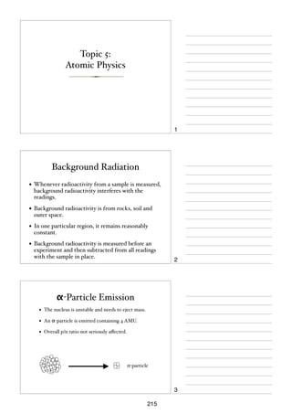
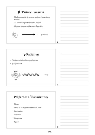
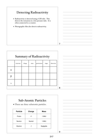
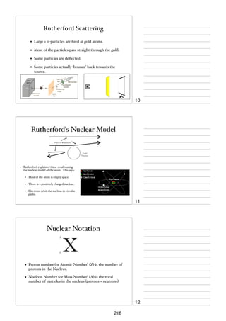
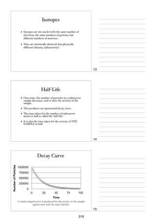
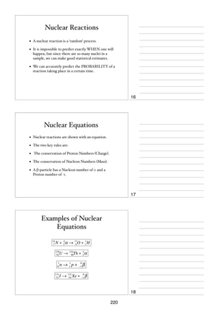
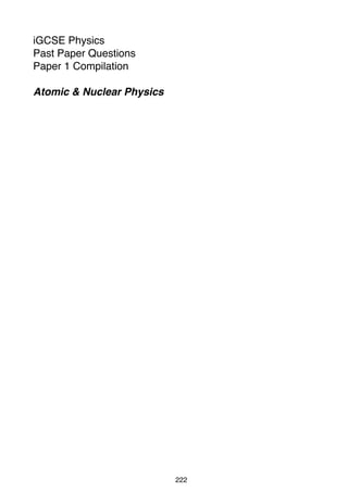
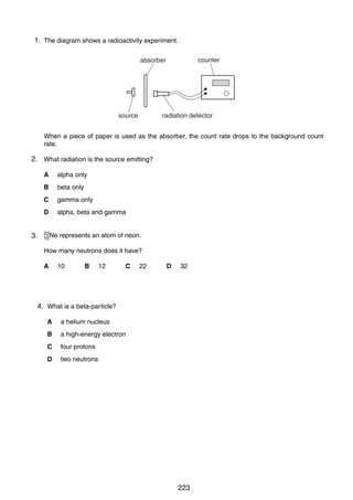
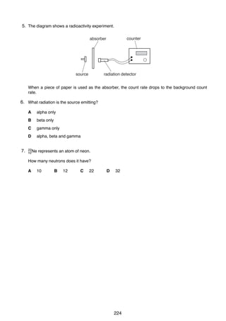
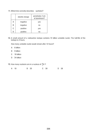
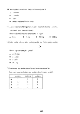
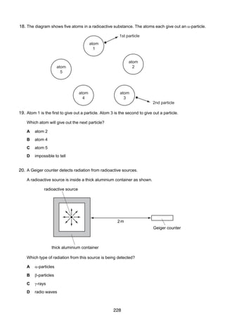

![12
10 Some liquid from an atomic power station is known to be radioactive. A sample of this liquid
is tested in a laboratory.
(a) In the space below, draw a labelled diagram of the test apparatus used to verify that
α-particles are emitted from the liquid.
[2]
(b) Explain how the apparatus may be used to estimate the quantity of α-radiation being
emitted from the sample.
..........................................................................................................................................
..........................................................................................................................................
..........................................................................................................................................
..........................................................................................................................................
..................................................................................................................................... [2]
(c) State any two safety precautions that the technician might take whilst making the test.
precaution 1 .....................................................................................................................
..........................................................................................................................................
precaution 2 .....................................................................................................................
..................................................................................................................................... [2]
0625/3/M/J/02
230
For
Examiner’s
Use](https://image.slidesharecdn.com/igcsenotesnumbered-140205153241-phpapp01/85/IGCSE-Physics-notes-232-320.jpg)
![12
For
Examiner’s
Use
11 (a) A radioactive isotope emits only α-particles.
(i)
In the space below, draw a labelled diagram of the apparatus you would use to
prove that no β-particles or γ-radiation are emitted from the isotope.
(ii)
Describe the test you would carry out.
...................................................................................................................................
...................................................................................................................................
...................................................................................................................................
...................................................................................................................................
(iii)
Explain how your results would show that only α-particles are emitted.
...................................................................................................................................
...................................................................................................................................
...................................................................................................................................
[6]
(b) Fig. 11.1 shows a stream of α-particles about to enter the space between the poles of a
very strong magnet.
N
α-particles
S
Fig. 11.1
Describe the path of the α-particles in the space between the magnetic poles.
..........................................................................................................................................
..........................................................................................................................................
......................................................................................................................................[3]
0625/3/M/J/03
231](https://image.slidesharecdn.com/igcsenotesnumbered-140205153241-phpapp01/85/IGCSE-Physics-notes-233-320.jpg)
![For
Examiner’s
Use
13
11 (a) α-particles can be scattered by thin gold foils.
Fig. 11.1 shows part of the paths of three α-particles.
Complete the paths of the three α-particles.
[3]
α-particle 1
α-particle 2
α-particle 3
gold nuclei
Fig. 11.1
(b) What does the scattering of α-particles show about atomic structure?
..........................................................................................................................................
..........................................................................................................................................
......................................................................................................................................[2]
(c) State the nucleon number (mass number) of an α-particle.
nucleon number = …………………[1]
© UCLES 2004
0625/03 M/J/04
232](https://image.slidesharecdn.com/igcsenotesnumbered-140205153241-phpapp01/85/IGCSE-Physics-notes-234-320.jpg)
![13
10 (a) Fig. 10.1 is the decay curve for a radioactive isotope that emits only β-particles.
For
Examiner’s
Use
400
count rate
counts / min
300
200
100
0
0
10
20
30
time / min
40
Fig. 10.1
Use the graph to find the value of the half-life of the isotope.
Indicate, on the graph, how you arrived at your value.
half-life …………………………. [2]
(b) A student determines the percentage of β-particles absorbed by a thick aluminium
sheet. He uses a source that is emitting only β-particles and that has a long half-life.
(i)
In the space below, draw a labelled diagram of the apparatus required, set up to
make the determination.
[2]
(ii)
List the readings that the student needs to take.
...................................................................................................................................
...................................................................................................................................
...................................................................................................................................
.............................................................................................................................. [3]
© UCLES 2005
0625/03/M/J/05
233
[Turn over](https://image.slidesharecdn.com/igcsenotesnumbered-140205153241-phpapp01/85/IGCSE-Physics-notes-235-320.jpg)
![12
11 Fig. 11.1 shows a beam of radiation that contains !-particles, "-particles and #-rays. The
beam enters a very strong magnetic field shown in symbol form by N and S poles.
For
Examiner’s
Use
N
beam of
radiation
S
Fig. 11.1
Complete the table below.
radiation
direction of deflection,
if any
charge carried by
radiation, if any
!-particles
"-particles
#-rays
[6]
Permission to reproduce items where third-party owned material protected by copyright is included has been sought and cleared where possible. Every reasonable
effort has been made by the publisher (UCLES) to trace copyright holders, but if any items requiring clearance have unwittingly been included, the publisher will
be pleased to make amends at the earliest possible opportunity.
University of Cambridge International Examinations is part of the University of Cambridge Local Examinations Syndicate (UCLES), which is itself a department
of the University of Cambridge.
© UCLES 2006
0625/03/M/J/06
234](https://image.slidesharecdn.com/igcsenotesnumbered-140205153241-phpapp01/85/IGCSE-Physics-notes-236-320.jpg)
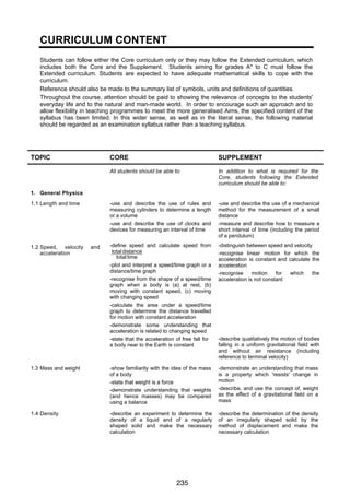
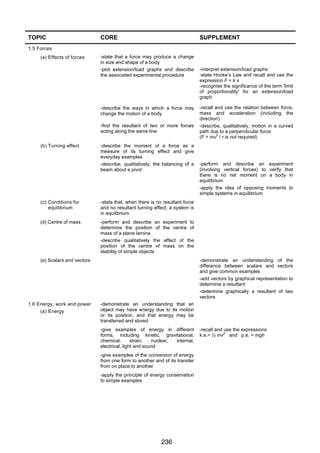
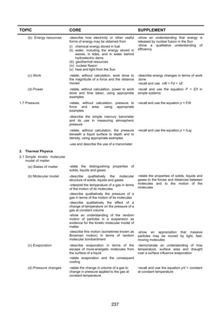
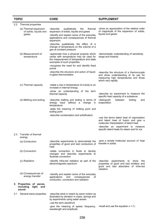
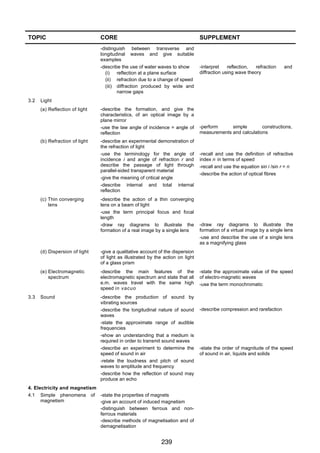
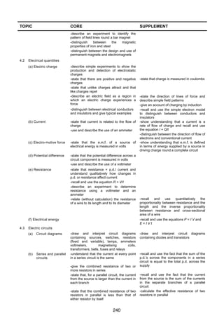
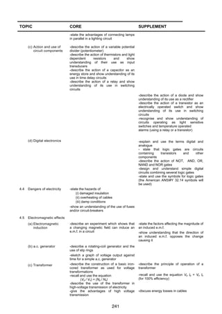
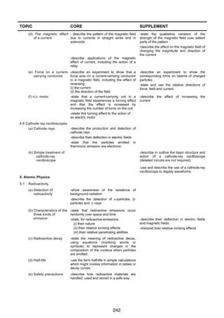
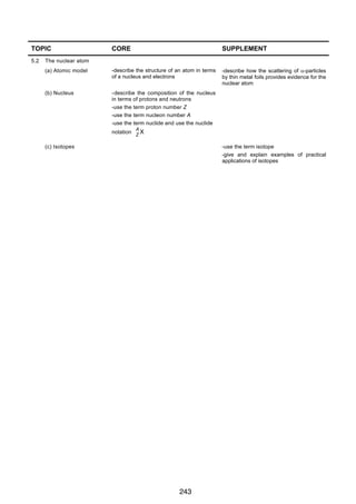

This document provides an overview of topics related to general physics concepts for the Cambridge iGCSE syllabus. It includes definitions, explanations, examples, and sample questions related to key concepts like length, time, speed, acceleration, distance-time graphs, speed-time graphs, density, forces, Newton's laws of motion, and moments. The document is intended to be a study guide and reference for students preparing for the Cambridge iGCSE physics exam. It covers the essential information about these foundational physics concepts in a concise yet comprehensive manner.