This document discusses composite construction and cambering of steel beams. It provides information on:
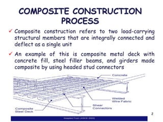
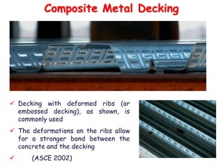
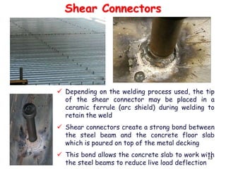
1) The composite construction process including use of composite metal decking, shear connectors, and concrete pouring to create a composite floor system that is stronger and stiffer than steel alone.
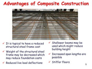
2) The advantages of composite construction such as reduced steel needs, lighter weight, and increased spans.
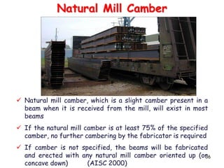
3) The cambering process of inducing a slight curvature in steel beams to compensate for deflection under loads in order to achieve a level floor slab.
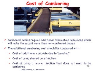
4) When cambering is appropriate such as for filler beams, and when it is not such as for moment connected beams. Alternative methods to cambering like