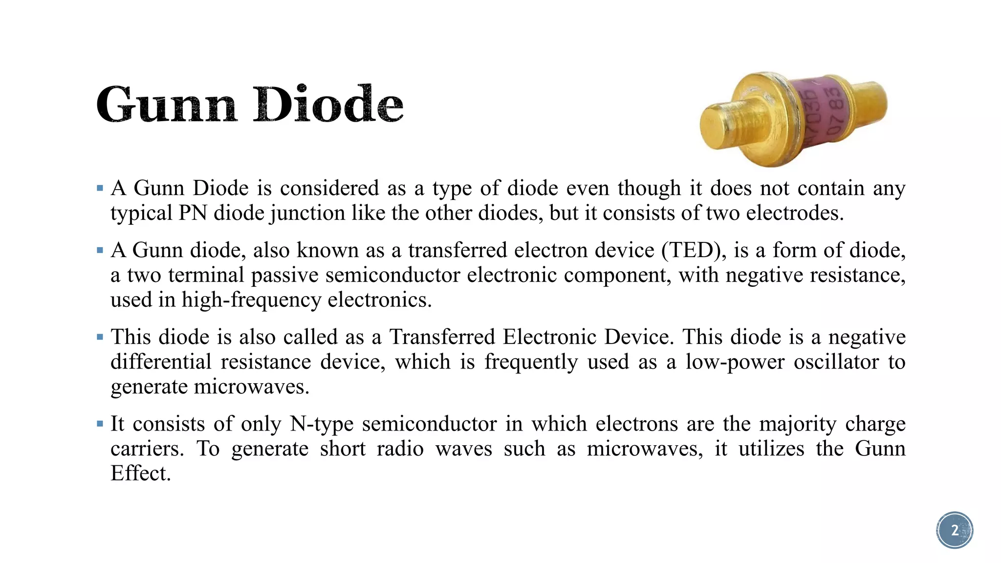
Department of Electronic and telecommunications Engineering
International Islamic University Chittagong
Submitted by,
Syed Mainul Islam
( ID: T-151020 )
Dept. of ETE, IIUC.
Submitted to,
Muhammad Mostafa Amir Faisal
( Assistant Professor )
Dept. of ETE, IIUC.
1
 A Gunn Diode is considered as a type of diode even though it does not contain any
typical PN diode junction like the other diodes, but it consists of two electrodes.
 A Gunn diode, also known as a transferred electron device (TED), is a form of diode,
a two terminal passive semiconductor electronic component, with negative resistance,
used in high-frequency electronics.
 This diode is also called as a Transferred Electronic Device. This diode is a negative
differential resistance device, which is frequently used as a low-power oscillator to
generate microwaves.
 It consists of only N-type semiconductor in which electrons are the majority charge
carriers. To generate short radio waves such as microwaves, it utilizes the Gunn
Effect.
2
 It was invented by John Battiscombe Gunn in 1960s; after his experiments on GaAs
(Gallium Arsenide), he observed a noise in his experiments’ results and owed this to
the generation of electrical oscillations at microwave frequencies by a steady electric
field with a magnitude greater than the threshold value.
 It was named as Gunn Effect after this had been discovered by John Battiscombe
Gunn.
 The Gunn Effect can be defined as generation of microwave power (power with
microwave frequencies of around a few GHz) whenever the voltage applied to a
semiconductor device exceeds the critical voltage value or threshold voltage value.
3
 Gunn diodes are used to build oscillators for generating microwaves with frequencies
ranging from 10 GHz to THz. It is a Negative Differential Resistance device – also
called as transferred electron device oscillator – which is a tuned circuit consisting of
Gunn diode with DC bias voltage applied to it. And, this is termed as biasing the diode
into negative resistance region.
 Due to this, the total differential resistance of the circuit becomes zero as the negative
resistance of the diode cancels with the positive resistance of the circuit resulting in
the generation of oscillations.
4
 This diode is made of a single piece of N-type semiconductor such as Gallium Arsenide and
InP (Indium Phosphide). GaAs and some other semiconductor materials have one extra-energy
band in their electronic band structure instead of having only two energy bands, viz. valence
band and conduction band like normal semiconductor materials.
 These GaAs and some other semiconductor materials consist of three energy bands, and this
extra third band is empty at initial stage.
 If a voltage is applied to this device, then most of the applied voltage appears across the active
region. The electrons from the conduction band having negligible electrical resistivity are
transferred into the third band because these electrons are scattered by the applied voltage. The
third band of GaAs has mobility which is less than that of the conduction band.
 Because of this, an increase in the forward voltage increases the field strength (for field
strengths where applied voltage is greater than the threshold voltage value), then the number of
electrons reaching the state at which the effective mass increases by decreasing their velocity,
and thus, the current will decrease.
 Thus, if the field strength is increased, then the drift velocity will decrease; this creates a
negative incremental resistance region in V-I relationship. Thus, increase in the voltage will
increase the resistance by creating a slice at the cathode and reaches the anode. But, to
maintain a constant voltage, a new slice is created at the cathode. Similarly, if the voltage
decreases, then the resistance will decrease by extinguishing any existing slice. 5
 Because of this, an increase in the forward voltage
increases the field strength (for field strengths
where applied voltage is greater than the threshold
voltage value), then the number of electrons
reaching the state at which the effective mass
increases by decreasing their velocity, and thus,
the current will decrease.
 Thus, if the field strength is increased, then the
drift velocity will decrease; this creates a negative
incremental resistance region in V-I relationship.
Thus, increase in the voltage will increase the
resistance by creating a slice at the cathode and
reaches the anode. But, to maintain a constant
voltage, a new slice is created at the cathode.
Similarly, if the voltage decreases, then the
resistance will decrease by extinguishing any
existing slice.
6
Figure: Characteristics of Gunn Diode
 Used as Gunn oscillators to generate frequencies ranging from 100mW 5GHz to 1W 35GHz
outputs. These Gunn oscillators are used for radio communications, military and commercial radar
sources.
 Used as sensors for detecting trespassers, to avoid derailment of trains.
 Used as efficient microwave generators with a frequency range of up to hundreds of GHz.
 Used for remote vibration detectors and rotational speed measuring tachometers.
 Used as a microwave current generator (Pulsed Gunn diode generator).
 Used in microwave transmitters to generate microwave radio waves at very low powers.
 Used as fast controlling components in microelectronics such as for the modulation of
semiconductor injection lasers.
 Used as sub-millimeter wave applications by multiplying Gunn oscillator frequency with diode
frequency.
7
8

Gunn diode

  • 1.
    Department of Electronicand telecommunications Engineering International Islamic University Chittagong Submitted by, Syed Mainul Islam ( ID: T-151020 ) Dept. of ETE, IIUC. Submitted to, Muhammad Mostafa Amir Faisal ( Assistant Professor ) Dept. of ETE, IIUC. 1
  • 2.
     A GunnDiode is considered as a type of diode even though it does not contain any typical PN diode junction like the other diodes, but it consists of two electrodes.  A Gunn diode, also known as a transferred electron device (TED), is a form of diode, a two terminal passive semiconductor electronic component, with negative resistance, used in high-frequency electronics.  This diode is also called as a Transferred Electronic Device. This diode is a negative differential resistance device, which is frequently used as a low-power oscillator to generate microwaves.  It consists of only N-type semiconductor in which electrons are the majority charge carriers. To generate short radio waves such as microwaves, it utilizes the Gunn Effect. 2
  • 3.
     It wasinvented by John Battiscombe Gunn in 1960s; after his experiments on GaAs (Gallium Arsenide), he observed a noise in his experiments’ results and owed this to the generation of electrical oscillations at microwave frequencies by a steady electric field with a magnitude greater than the threshold value.  It was named as Gunn Effect after this had been discovered by John Battiscombe Gunn.  The Gunn Effect can be defined as generation of microwave power (power with microwave frequencies of around a few GHz) whenever the voltage applied to a semiconductor device exceeds the critical voltage value or threshold voltage value. 3
  • 4.
     Gunn diodesare used to build oscillators for generating microwaves with frequencies ranging from 10 GHz to THz. It is a Negative Differential Resistance device – also called as transferred electron device oscillator – which is a tuned circuit consisting of Gunn diode with DC bias voltage applied to it. And, this is termed as biasing the diode into negative resistance region.  Due to this, the total differential resistance of the circuit becomes zero as the negative resistance of the diode cancels with the positive resistance of the circuit resulting in the generation of oscillations. 4
  • 5.
     This diodeis made of a single piece of N-type semiconductor such as Gallium Arsenide and InP (Indium Phosphide). GaAs and some other semiconductor materials have one extra-energy band in their electronic band structure instead of having only two energy bands, viz. valence band and conduction band like normal semiconductor materials.  These GaAs and some other semiconductor materials consist of three energy bands, and this extra third band is empty at initial stage.  If a voltage is applied to this device, then most of the applied voltage appears across the active region. The electrons from the conduction band having negligible electrical resistivity are transferred into the third band because these electrons are scattered by the applied voltage. The third band of GaAs has mobility which is less than that of the conduction band.  Because of this, an increase in the forward voltage increases the field strength (for field strengths where applied voltage is greater than the threshold voltage value), then the number of electrons reaching the state at which the effective mass increases by decreasing their velocity, and thus, the current will decrease.  Thus, if the field strength is increased, then the drift velocity will decrease; this creates a negative incremental resistance region in V-I relationship. Thus, increase in the voltage will increase the resistance by creating a slice at the cathode and reaches the anode. But, to maintain a constant voltage, a new slice is created at the cathode. Similarly, if the voltage decreases, then the resistance will decrease by extinguishing any existing slice. 5
  • 6.
     Because ofthis, an increase in the forward voltage increases the field strength (for field strengths where applied voltage is greater than the threshold voltage value), then the number of electrons reaching the state at which the effective mass increases by decreasing their velocity, and thus, the current will decrease.  Thus, if the field strength is increased, then the drift velocity will decrease; this creates a negative incremental resistance region in V-I relationship. Thus, increase in the voltage will increase the resistance by creating a slice at the cathode and reaches the anode. But, to maintain a constant voltage, a new slice is created at the cathode. Similarly, if the voltage decreases, then the resistance will decrease by extinguishing any existing slice. 6 Figure: Characteristics of Gunn Diode
  • 7.
     Used asGunn oscillators to generate frequencies ranging from 100mW 5GHz to 1W 35GHz outputs. These Gunn oscillators are used for radio communications, military and commercial radar sources.  Used as sensors for detecting trespassers, to avoid derailment of trains.  Used as efficient microwave generators with a frequency range of up to hundreds of GHz.  Used for remote vibration detectors and rotational speed measuring tachometers.  Used as a microwave current generator (Pulsed Gunn diode generator).  Used in microwave transmitters to generate microwave radio waves at very low powers.  Used as fast controlling components in microelectronics such as for the modulation of semiconductor injection lasers.  Used as sub-millimeter wave applications by multiplying Gunn oscillator frequency with diode frequency. 7
  • 8.