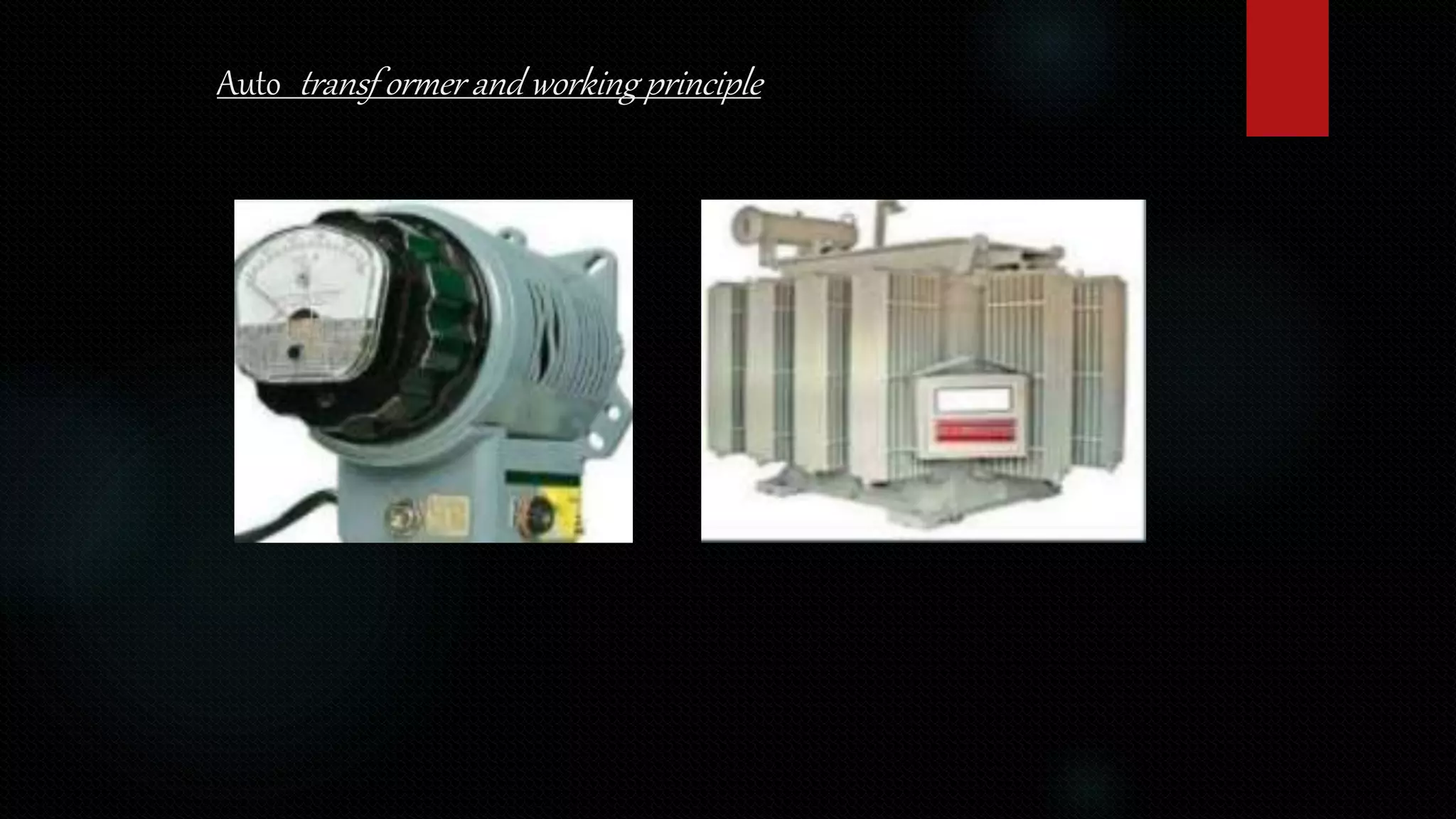
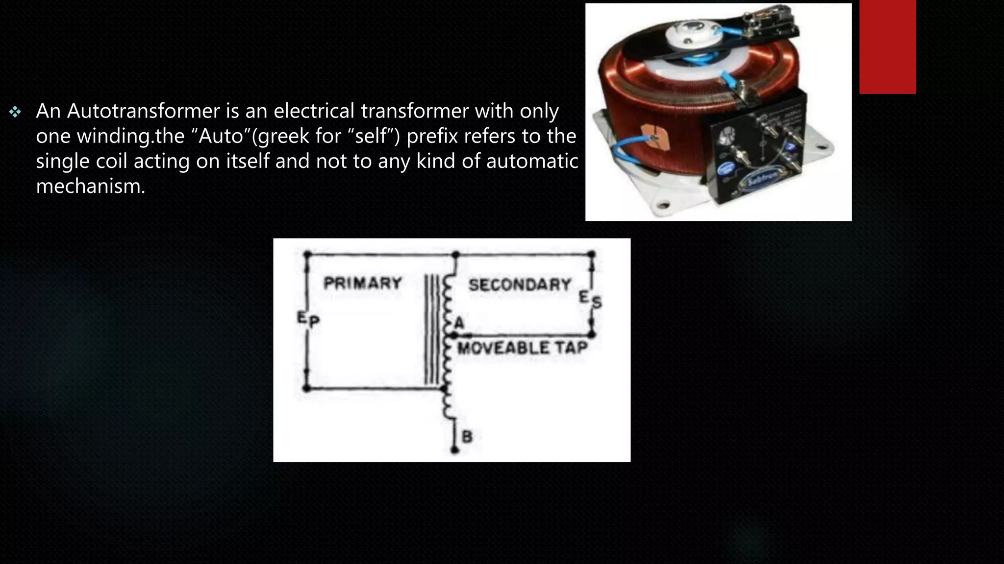
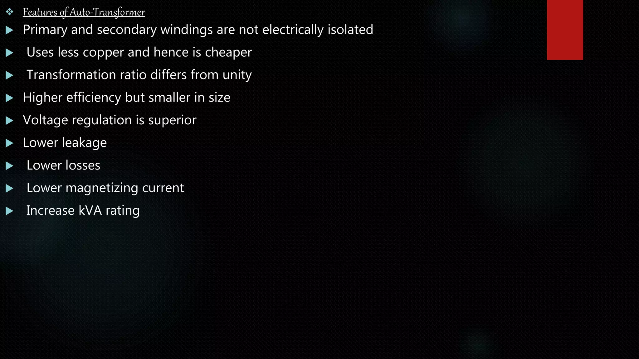
- An autotransformer has a single winding that acts as both the primary and secondary winding. It uses less copper than a two-winding transformer, resulting in lower costs. However, it does not provide isolation between primary and secondary voltages.
- Key features include higher efficiency, smaller size, superior voltage regulation, and lower losses compared to a two-winding transformer. The output power depends on the transformation ratio. Savings in copper increases as the ratio approaches 1.
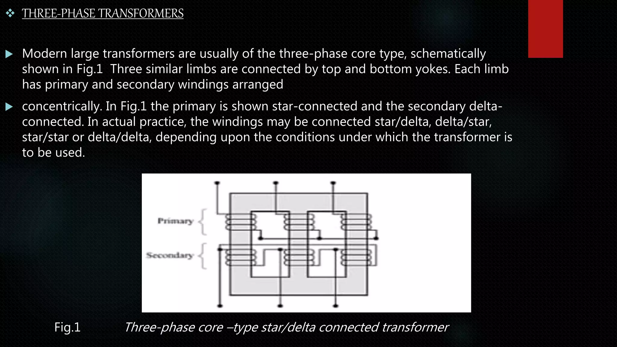
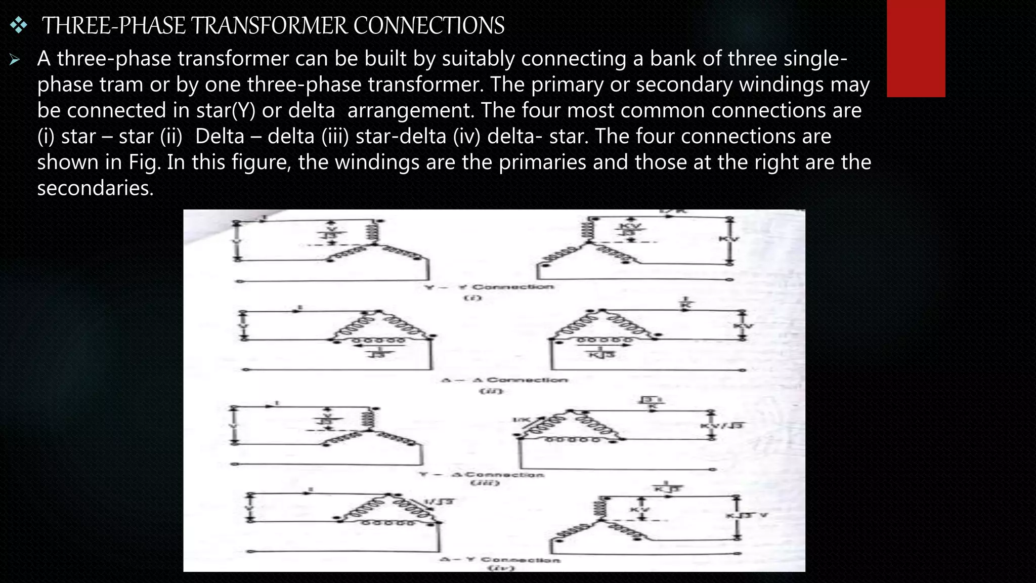
- Common three-phase transformer connections include star-star, delta-delta, star-delta, and delta-star, which determine how line voltages and currents are distributed across the windings.

![ Output power
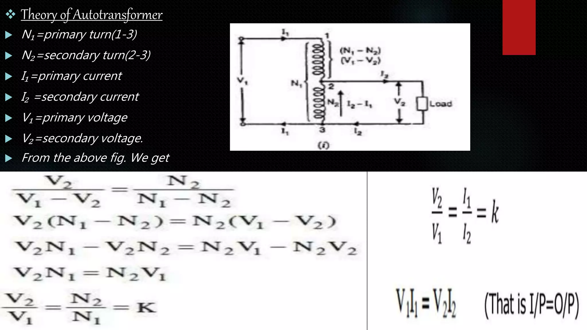
The primary and secondary windings of an auto-transformer are connected
magnetically as well as electrically. So the power transferred from primary to secondary
is inductively as well as conductively.
Output apparent power = V₂I₂
Apparent power transferred inductively = V₂(I₂-I₁) = V₂(I₂-KI₂)
= V₂l₂(1-K)= V₁I₁(1-K)
Power transferred inductively = Input x (1-K)
Power transferred conductively = Input - Input (1-K)
= Input [1-(1-K)]
= K x Input](https://image.slidesharecdn.com/21btcs030hybeepresentation-220111200420/75/AUTO-TRANSFORMER-AND-THREE-PHASE-TRANSFORMER-7-2048.jpg)