Download as PDF, PPTX


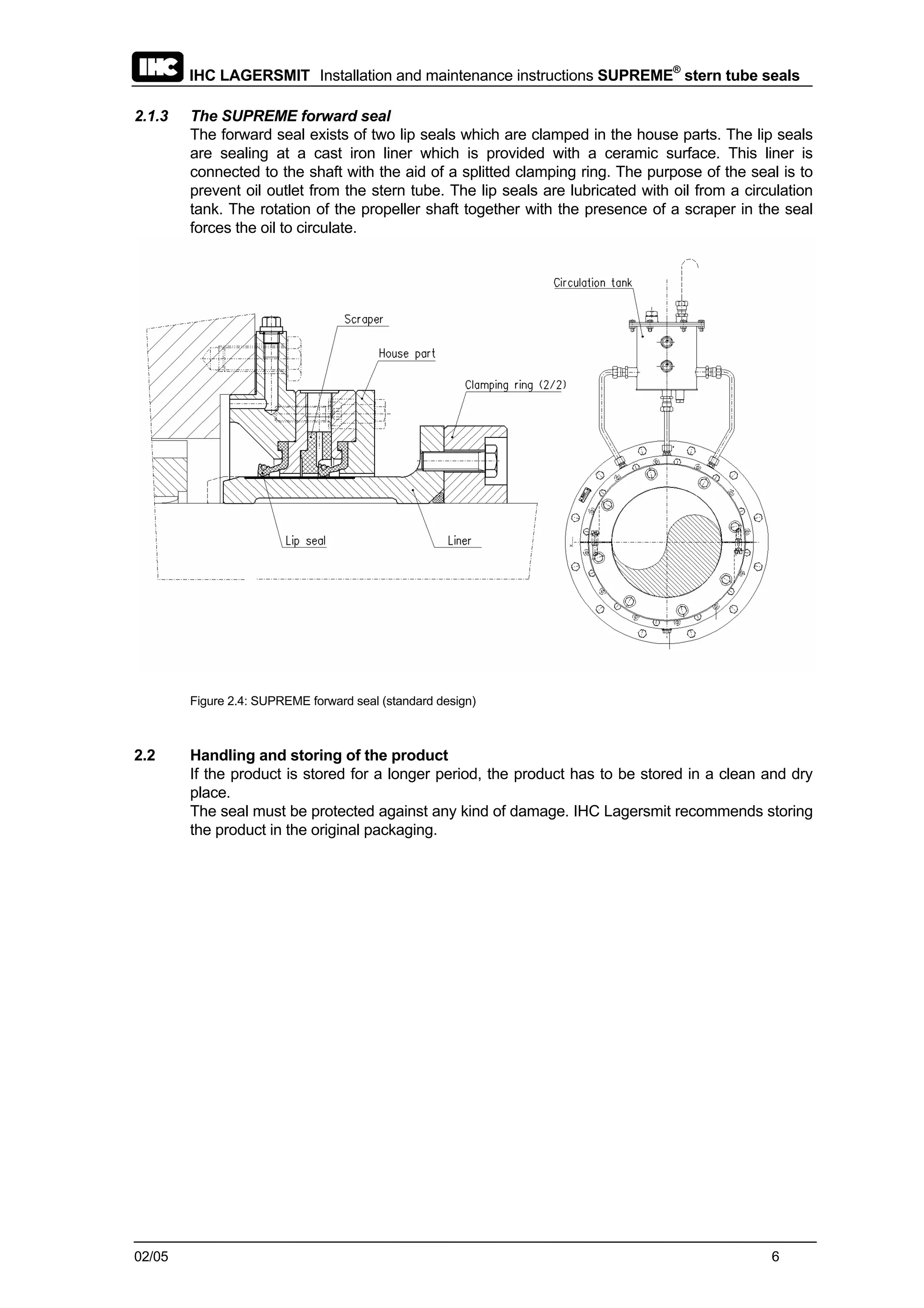


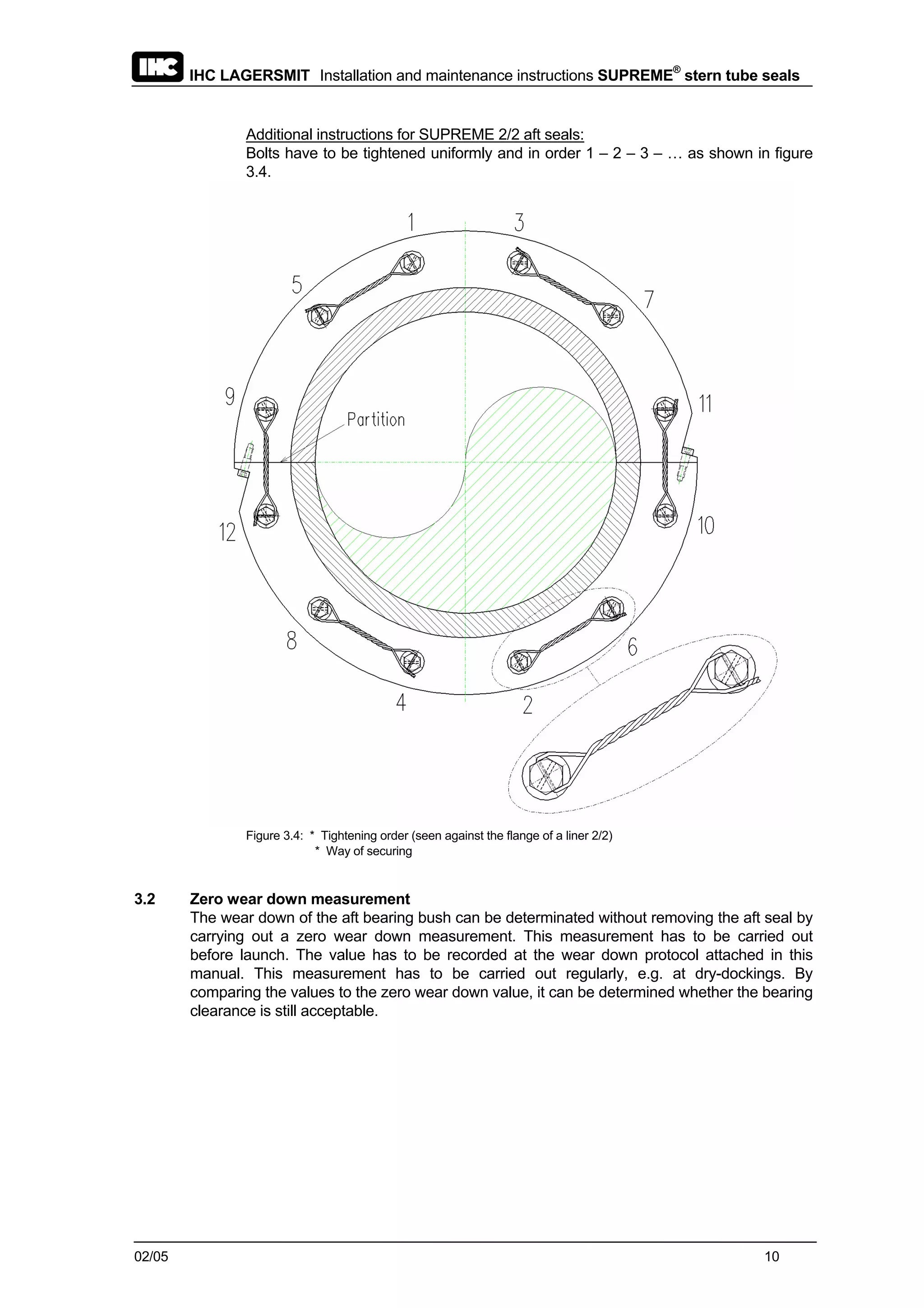
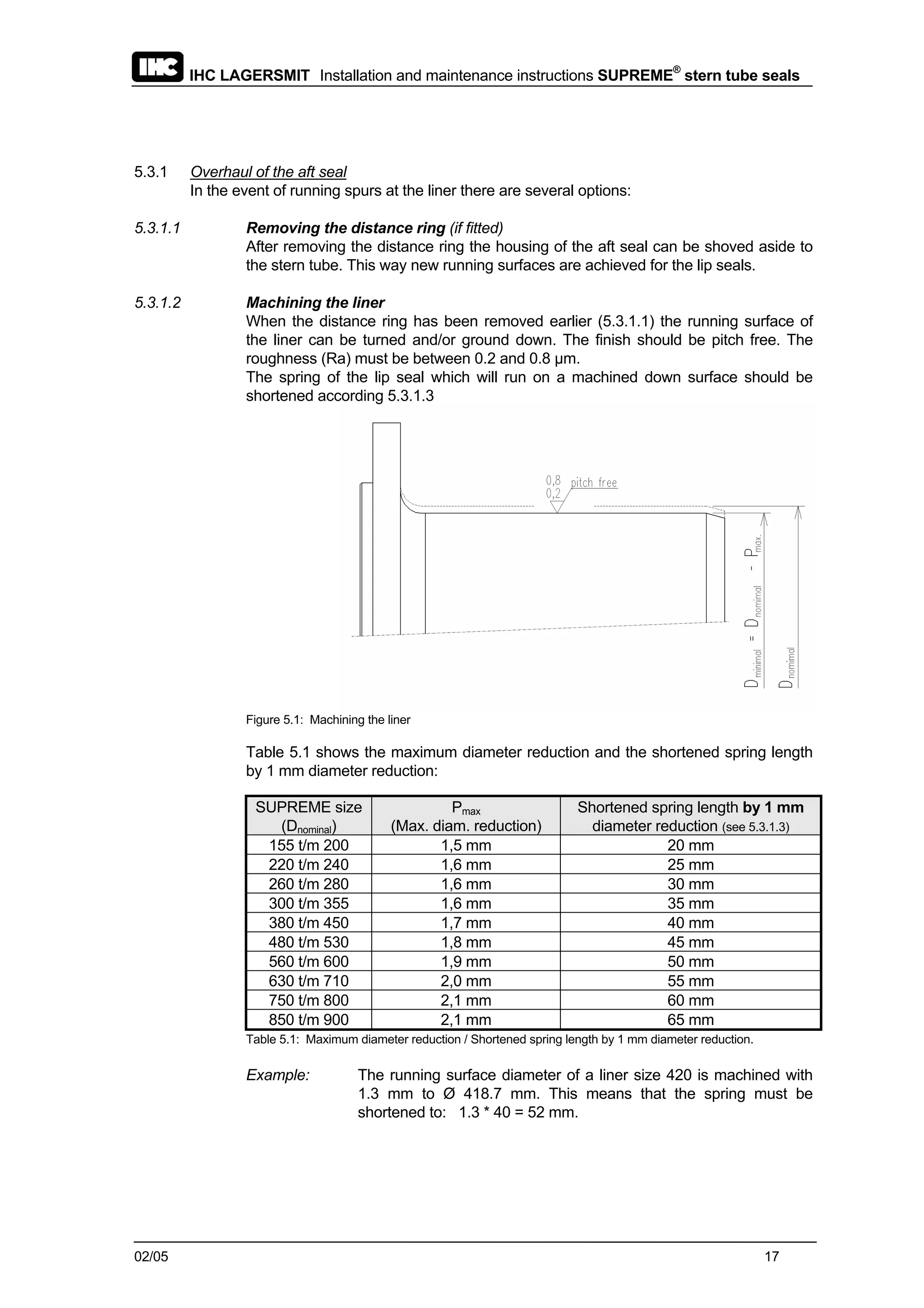
![IHC LAGERSMIT Installation and maintenance instructions SUPREME®
stern tube seals
02/05 9
7. Check the run-out of the liner according figure 3.3
Fig. 3.3: Checking the run-out
The maximum allowed shaft movement depends on the size of the SUPREME seal.
The next table shows the maximum allowed clock gauge deflections:
SUPREME size Maximum allowed clock gauge deflection
155 t/m 300 0,09 mm
330 t/m 500 0,12 mm
530 t/m 900 0,15 mm
Table 3.2: Maximum allowed clock gauge deflections
8. Fasten and secure the bolts.
Table 3.3 shows the torque moments. The bolts need to be redrawed after fitting.
The bolts have to be secured with the help of securing wire according figure 3.4.
Bolt
Torque moment
Aft seal
Torque moment
Forward seal
M8 20 [Nm] 22 [Nm]
M10 45 [Nm] 44 [Nm]
M12 75 [Nm] 74 [Nm]
M16 120 [Nm] 165 [Nm]
M20 205 [Nm] 314 [Nm]
M24 354 [Nm] 549 [Nm]
Table 3.3 : Torque moments](https://image.slidesharecdn.com/strentube-130728110227-phpapp01/75/Strentube-9-2048.jpg)

![IHC LAGERSMIT Installation and maintenance instructions SUPREME®
stern tube seals
02/05 12
Installing:
1. Take the precautions written at page 7 of this manual;
2. Oil the shaft;
3. Slid the complete stern tube seal, including the gasket, brackets and O-ring onto the
shaft;
4. Fit the seal against the stern tube;
Mind the correct position of the gasket and the bleed plug.
With respect to the alignment do not fasten the bolts of the flange ring yet.
5. Couple the propeller shaft;
6. Remove the brackets;
If the brackets are not removed the installation will cause
damage when the seal is put into operation.
The brackets do not prescribe the built-in length.
7. Adjust and mount the clamping ring onto the propeller shaft;
The adjusting size is given in table 3.4.
Adjusting
size [mm]
Adjusting
size [mm]
Adjusting
size [mm]
SUPREME
Size
Min. Max.
SUPREME
Size
Min. Max.
SUPREME
Size
Min. Max.
155 to 190 57 67 355 to 380 79 89 670 130 145
200 to 220 62 72 400 to 500 84 99 710 to 750 120 135
240 to 260 67 77 530 89 104 800 to 850 123 138
280 69 79 560 to 600 90 105 900 138 153
300 to 330 74 84 630 105 120 950 to 1000 148 163
Table 3.4: Adjusting sizes](https://image.slidesharecdn.com/strentube-130728110227-phpapp01/75/Strentube-12-2048.jpg)


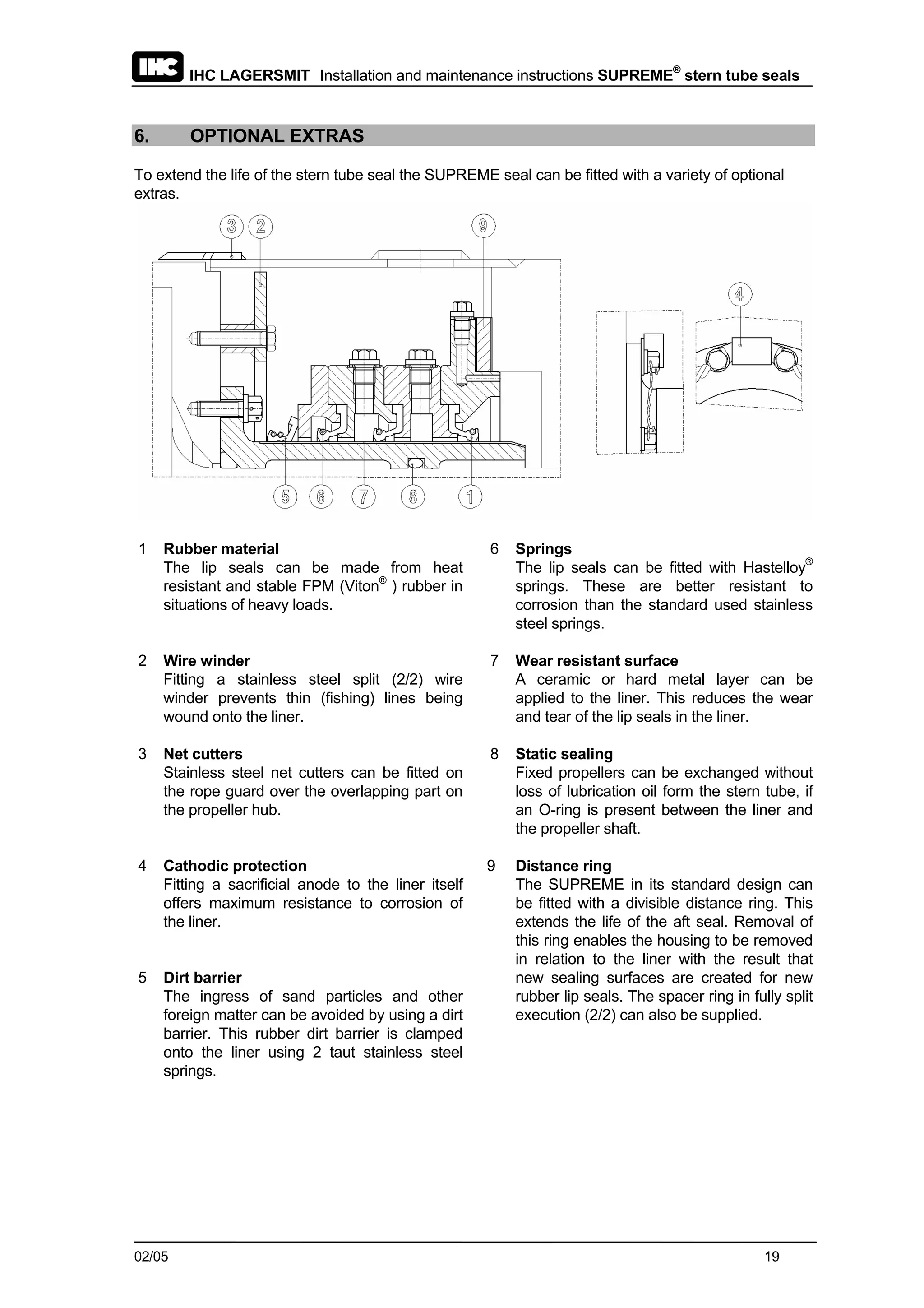

This document provides installation and maintenance instructions for IHC Lagersmit's SUPREME stern tube seals. It includes details on: 1. Installing the aft and forward seals, including checking alignment, built-in length, and run-out tolerances. 2. Taking an initial zero wear down measurement of the aft bearing bush before launch. 3. Filling the stern tube, circulation tank, and any additional lubrication tanks with the specified mineral or biological oil.


![Shaft Alignment Trainer [SAT] presentation](https://cdn.slidesharecdn.com/ss_thumbnails/satpresentation-130805143252-phpapp01-thumbnail.jpg?width=640&height=640&fit=bounds)