The document provides a comprehensive overview of tools and techniques for commissioning and maintaining photovoltaic (PV) systems, emphasizing safety and performance testing per IEC 62446-1 standards. It details the understanding of overvoltage categories, the importance of using appropriately rated test equipment, and outlines the specific testing workflow during installation and maintenance. It also stresses the significance of proper grounding, voltage, and insulation resistance testing to ensure reliability and longevity in PV installations.
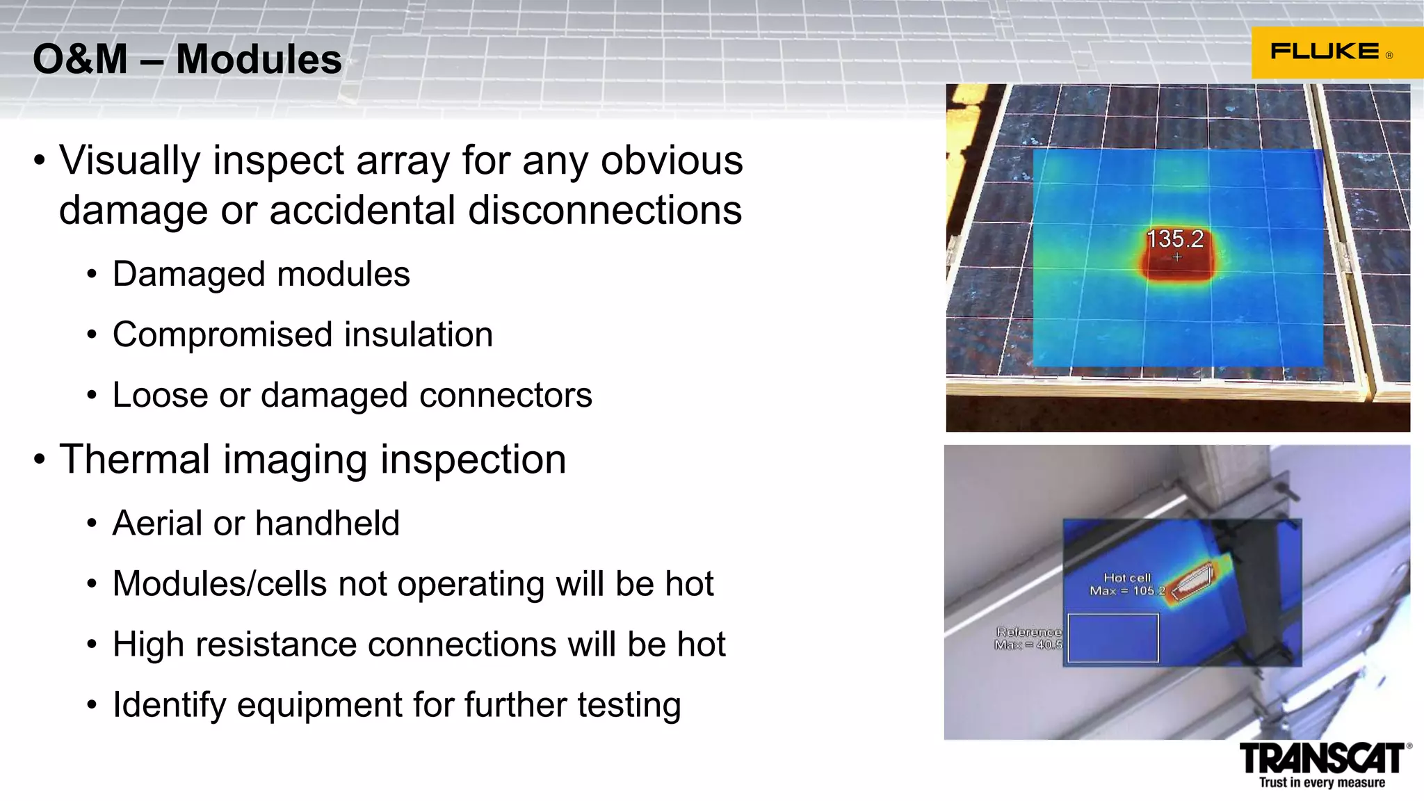
![When installing, commissioning, and executing maintenance on PV systems,
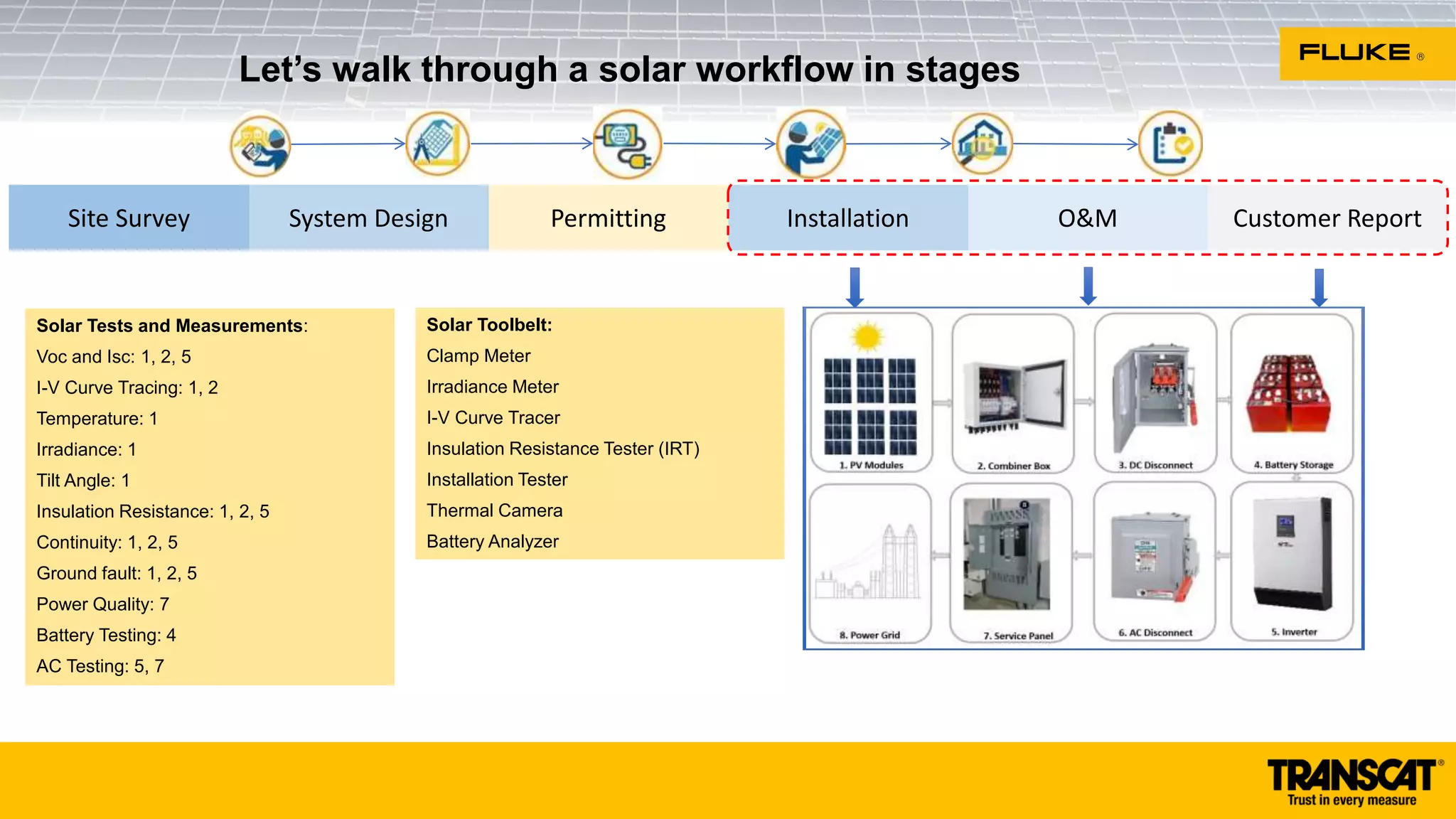
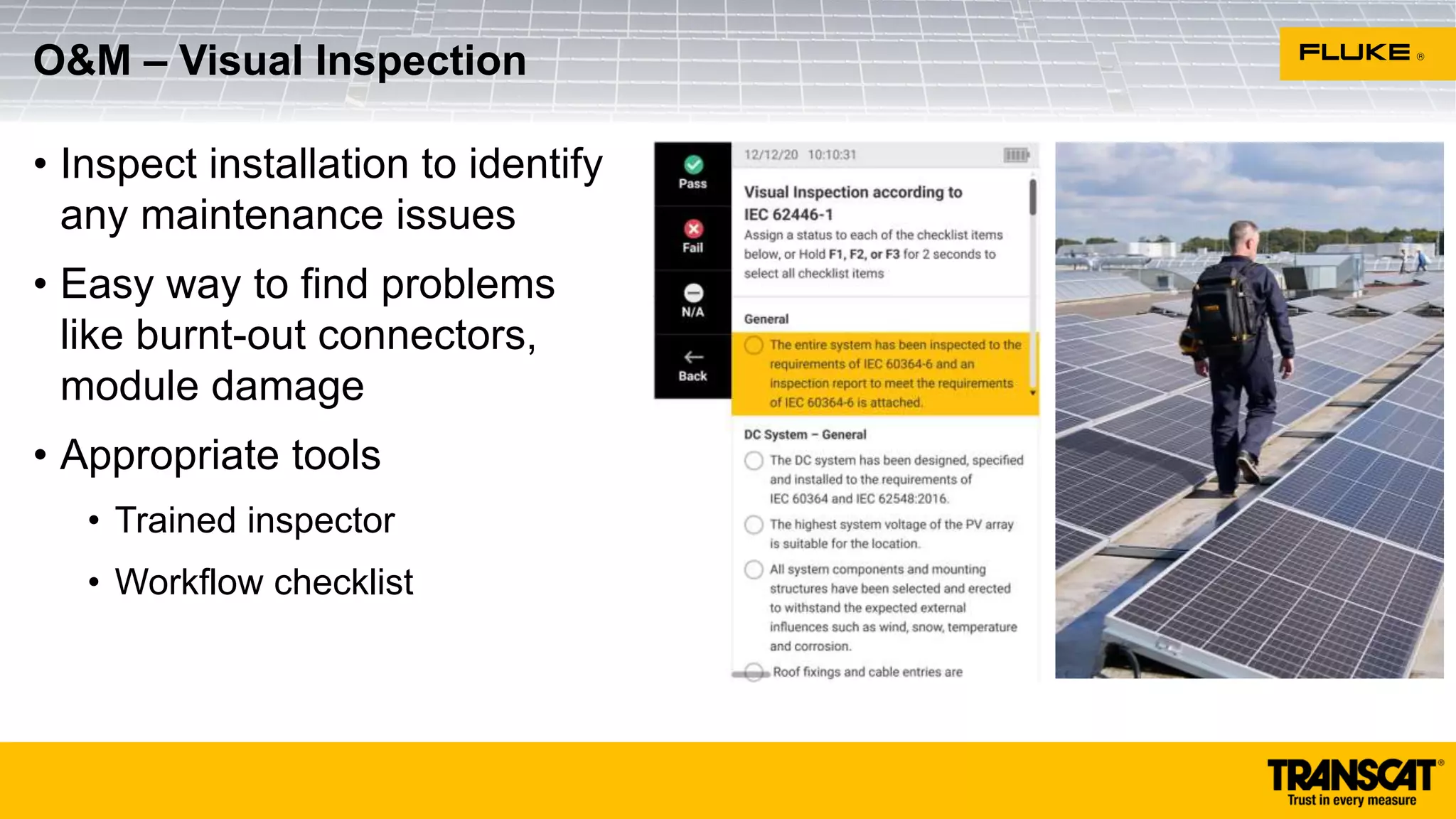
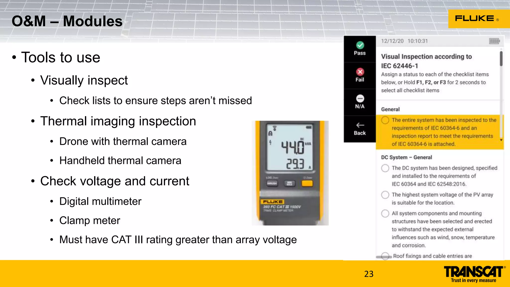
technicians verify safety and performance per IEC 62446-1 standards
Safety
IEC 62446-1 requires that the AC circuits are tested first, then the following six
DC circuit tests need to be performed, preferably in this order:
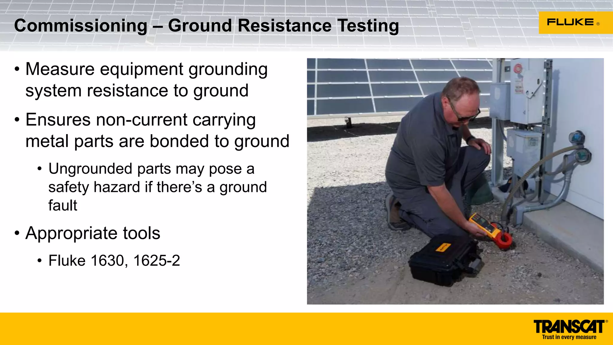
1) Test continuity of equipment and system grounding conductors
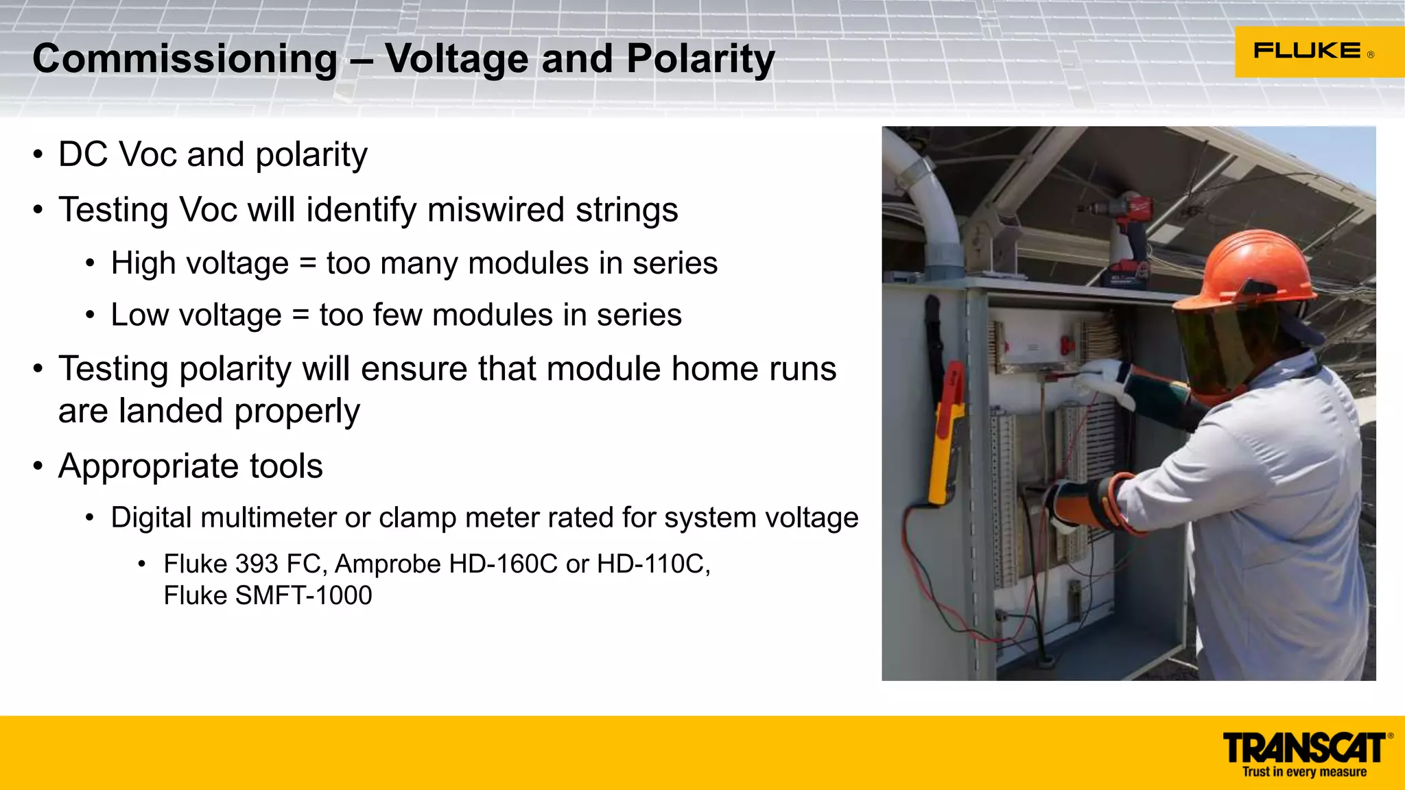
2) Test polarity of all DC cables
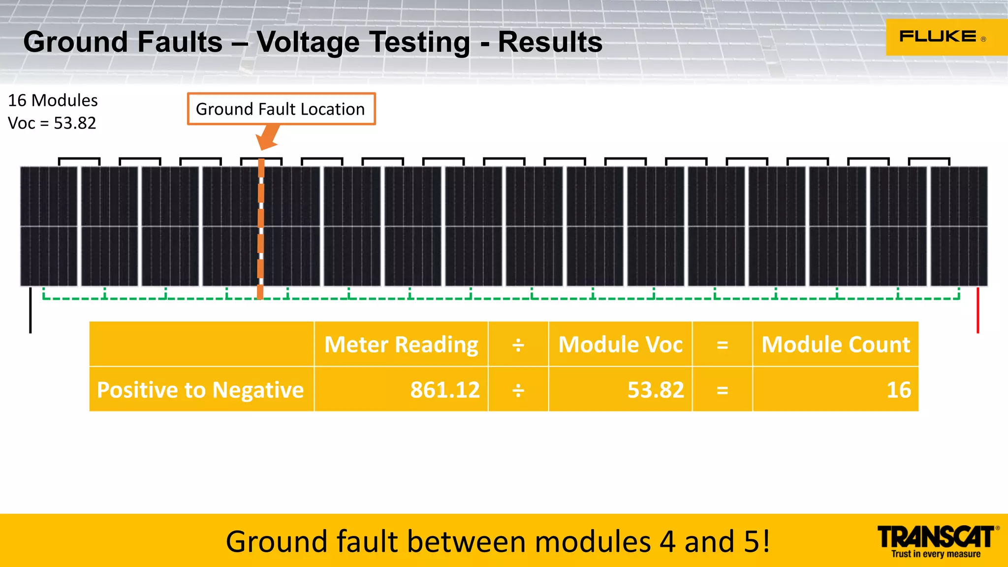
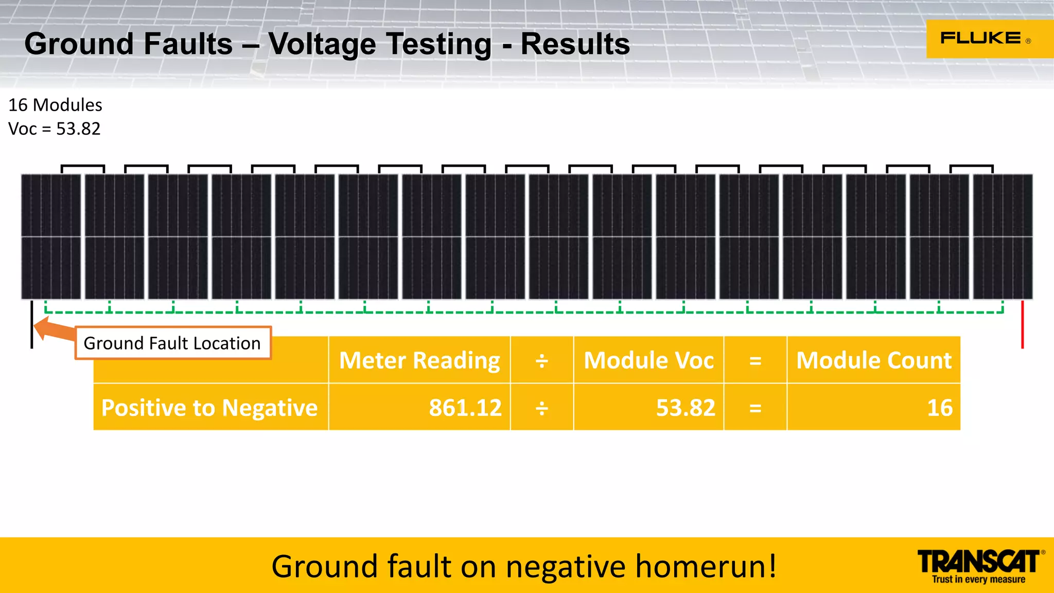
3) Test open-circuit voltage [Voc] for each PV source circuit
4) Test short-circuit current [Isc] for each PV source circuit
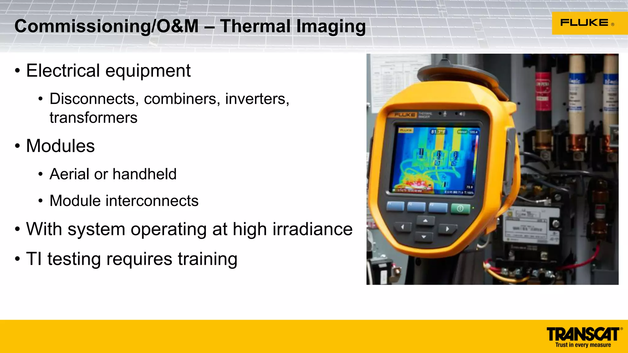
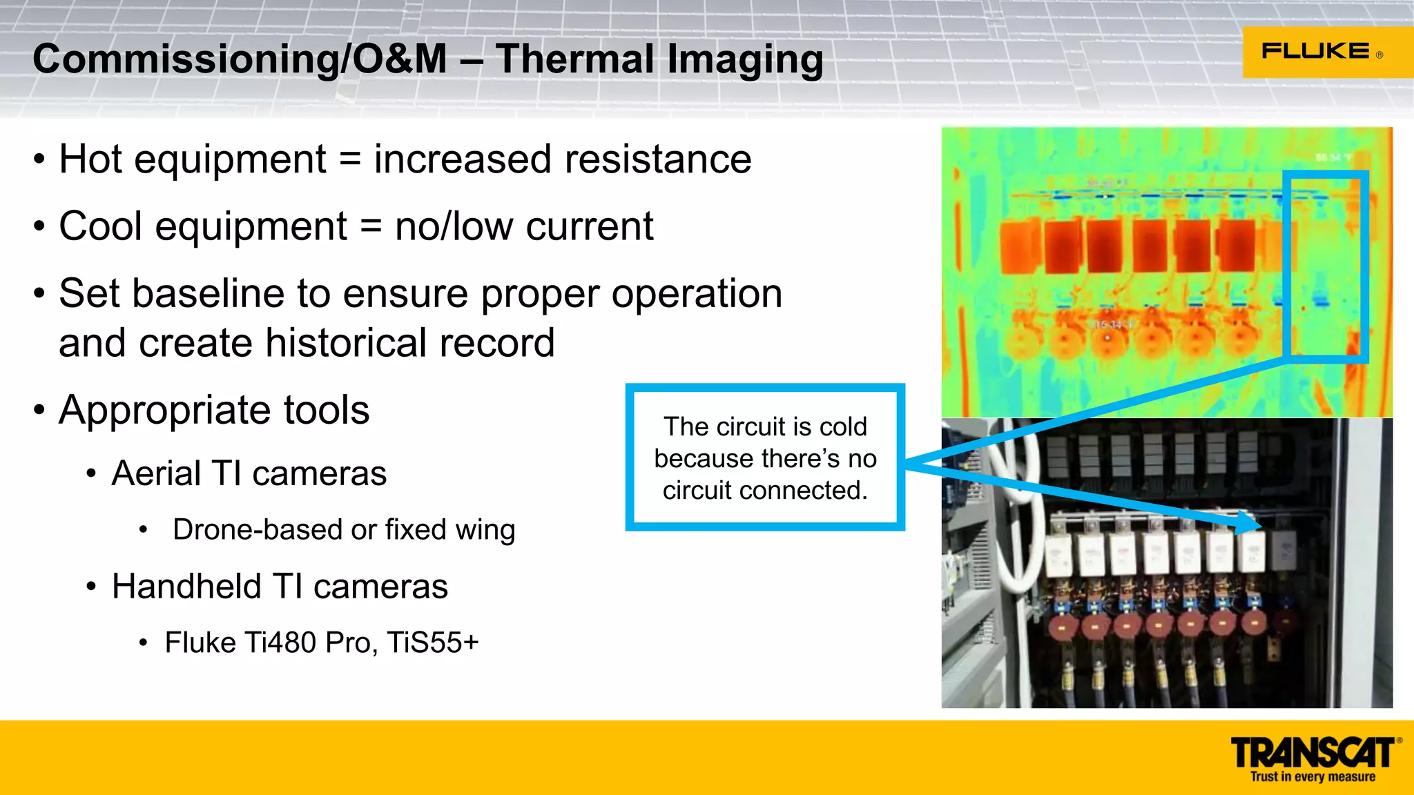
5) Test functionality of major system components
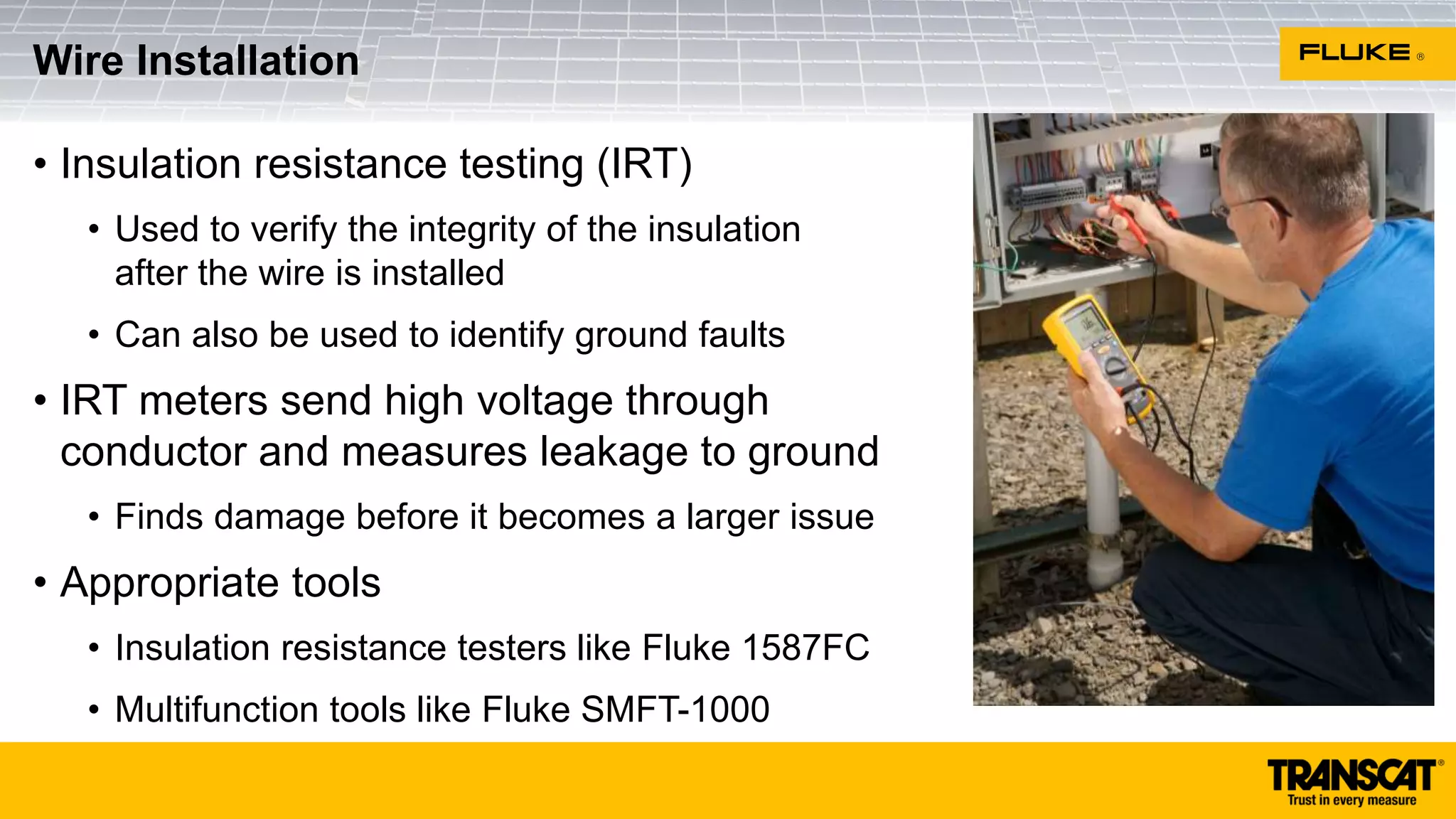
6) Test the insulation resistance of the DC circuit conductors
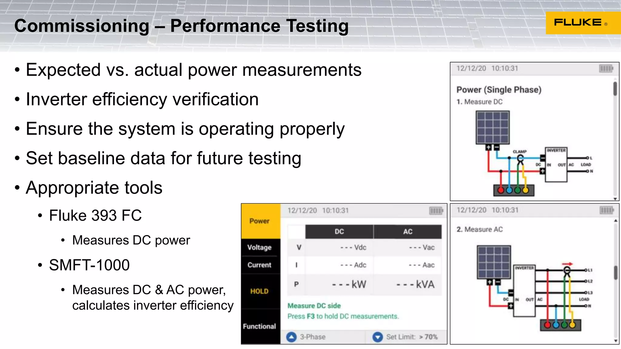
Performance
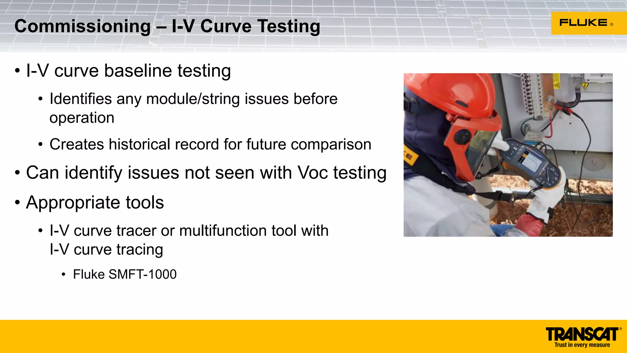
7) I-V Curve tracing and associated software analysis
IEC Testing Requirements for PV Systems
Utilities & 3rd
Party Service
Techs
PV Installers &
Maintenance Techs
Safety and Performance testing during installation, commissioning and
maintenance ensures safety, reliability and longevity of PV installations](https://image.slidesharecdn.com/transcatnabcep2023presentationw-animations-tcat-230420200849-74b3a535/75/Tools-and-Techniques-for-Commissioning-and-Maintaining-PV-Systems-8-2048.jpg)