Download to read offline
![TP32MTT.03
TP32MTT.03.1
[ GB ] Probes for
soil thermal profile
measurement](https://image.slidesharecdn.com/tp32mtt03den-150526085424-lva1-app6892/85/TP32MTT03D-Soil-temperature-Profile-DELTAOHM-1-320.jpg)
![[ GB ][ GB ] Description
• Temperature measurement at 7 levels (TP32MTT.03) or 6 levels (TP32MTT.03.1)
• In accordance with the requirements of the World Meteorological Organization
• RS485 digital output with MODBUS‑RTU protocol
• Accurate and stable measure over time
• Degree of protection IP 68
• Minimal invasiveness in the soil
APPLICATION
• Agriculture
• Geothermic studies
Description
The temperature probe TP32MTT.03 is equipped with seven Pt100 1/3 DIN sensors for
the measurement of temperature at depth: +5 cm, 0, ‑5 cm, ‑10 cm, ‑20 cm, ‑50 cm,
‑1 m with respect to the soil level, according to the indications of the World Meteoro‑
logical Organization (WMO).
The probe TP32MTT.03.1 is equipped with six Pt100 1/3 DIN sensors for the measure‑
ment of temperature at depth: +5 cm, 0, ‑5 cm, ‑10 cm, ‑20 cm, ‑50 cm with respect
to the soil level.
The fi breglass tube ensures a perfect impermeability and a high thermal insolation
along the vertical axis.
The RS485 digital output with MODBUS RTU protocol allows the use of even very
long connection cables. It can be connected to the datalogger HD32MT.1 and
HD32MT.3, or to any other datalogger with RS485 MODBUS RTU input.
The M12 connector present on the hand grip of the probe allows an easy connection
of the cable. Cable length (optional) 2, 5 or 10 m, with open wires at the end.
Power supply 6…30 Vdc.
Technical specifications
Sensors Pt100 1/3 DIN
Resolution 0.01 °C
Accuracy ± 0.1 °C @ 0 °C
Working temperature ‑40…+85 °C
Temperature drift 0.003 %/°C @ 20 °C
Power supply 6…30 Vdc
Consumption 5 mA @ 12 Vdc
Output RS485 with MODBUS‑RTU protocol
Connection 8‑pole M12 male connector
Cable Optional, with 8 poles with length of 2, 5 or 10 m (to be de‑
fi ned at the order) with open wires at the end.
Protection Degree IP 68
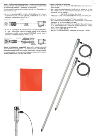
Fig. 2: installation
Indicate the presence of the probe during the maintenance operations of the soil
(e.g. lawn mowing, ploughing, mechanized harvesting, etc.).
To remove the probe from the soil, insert a pin into the Ø 8mm hole at the top of the
handle and pull it upwards. Remove the probe vertically, avoiding its inclination
during extraction to avoid damaging the stem.
Connect the M12 connector as shown in Fig 3 and 4. On request, 5 or 10 m stand-
ard cables with 8-pole M12 female connector are available (other lengths
available on request).
Connector
numbering
Function Colour
1 Negative power supply Black
2 Positive power supply Red
3 Not connected
4 RS485 A/‑ Brown
5 RS485 B/+ White
6 Not connected
7 Not connected
8 Not connected
Fig. 3: connections
Fig. 4: RS485 connection
Fig. 1: dimensions of the probe TP32MTT.03 (mm)
Installation
By means of an accessory, perform a hole into the soil deep enough to accommodate
the stem of the probe. Never use the probe to make the hole in the soil, to avoid me‑
chanical damage to the probe itself.
Once the hole has been performed in the soil, insert the stem of the probe so that the
indicator of the zero level is in correspondence with the surface of the soil. The probe
must be stable in a vertical position.
After the introduction of the probe into the hole, fi ll in the empty spaces between
the soil and the stem of the probe with some soil made powder. To obtain accurate
measurements, the soil should be in contact with the stem.
Soil level
Groove to apply the fl ag
indicating placememt position
Hole Ø 8mm for the introduction of a
pin for the extraction of the probe
Soil level indication on the
stem of the probe
Soil level
Probe M12 male
connector
Cable CPM12-8P...
Termination Termination
Other sensors with
RS485 output
PLC, datalogger or
converter RS485/USB
or RS485/RS232 for PC
Probe M12
male connector Cavo CPM12-8P...
Shield
White
Brown
Black
Power supply
6...30 Vdc
Red](https://image.slidesharecdn.com/tp32mtt03den-150526085424-lva1-app6892/85/TP32MTT03D-Soil-temperature-Profile-DELTAOHM-2-320.jpg)
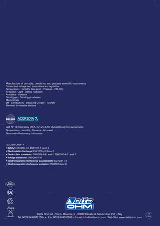
![6. Send the following serial commands to set the RS485 MODBUS parameters:
Command Reply Description
CMAnnn &| Set address RS485 to nnn
Ranging from 1 to 247. Preset on 1
CMBn &| Set RS485 Baud Rate: n=0 ⇒ 9600, n=1 ⇒ 19200
Preset on 1 ⇒ 19200
CMPn &| Set RS485 transmission mode (data bits, parity, stop bits):
n=0 ⇒ 8N1, n=1 ⇒ 8N2, n=2 ⇒ 8E1
n=3 ⇒ 8E2, n=4 ⇒ 8O1, n=5 ⇒ 8O2
Preset on 2 ⇒ 8E1
CMWn &| Set receiving mode after RS485 transmission:
n=0 ⇒ Violate protocol and go in Tx mode right after Tx
n=1 ⇒ Respect protocol and wait 3.5 characters after Tx
Preset on 1 ⇒ Respect the protocol
7. It is possible to check the settings of the parameters by sending the following
commands:
Command Reply Description
RMA Address Read RS485 address
RMB
Baud Rate
(0,1)
Read RS485 Baud Rate: 0 ⇒ 9600, 1 ⇒ 19200
RMP
Tx Mode
(0,1,2,3,4,5)
Read RS485 transmission mode:
0 ⇒ 8N1, 1 ⇒ 8N2, 2 ⇒ 8E1, 3 ⇒ 8E2, 4 ⇒ 8O1, 5 ⇒ 8O2
RMW
Rx Mode
(0,1)
Read reception mode after RS485 transmission:
0 ⇒ Violate the protocol and go in Tx mode right after Tx
1 ⇒ Respect the protocol and wait 3.5 characters after Tx
Note: the command CAL USER ON is not required for reading the settings.
OPERATING MODE
The probe enters RS485 MODBUS‑RTU mode after 10 seconds from power on.During the
first 10 seconds from power on,the probe does not respond to any request from the MOD‑
BUS master unit.After 10 seconds, it is possible to send MODBUS requests to the probe.
Reading the measurements
In MODBUS mode, it is possible to read, through the function code 04h (Read Input Reg‑
isters), the measured values and the status of the probe. The following table lists the
available MODBUS Input Registers:
MODBUS Input Registers
Register
Number
Register
Address
Datum Format
1 0
Temperature in °C at -1 m from the soil [x100]
Note: the value has no meaning for the probe
TP32MTT.03.1
16-bit integer
2 1 Temperature in °C at -50 cm from the soil [x100] 16-bit integer
3 2 Temperature in °C at -20 cm from the soil [x100] 16-bit integer
4 3 Temperature in °C at -10 cm from the soil [x100] 16-bit integer
5 4 Temperature in °C at -5 cm from the soil [x100] 16-bit integer
6 5 Temperature in °C at the soil level [x100] 16-bit integer
7 6 Temperature in °C at +5 cm from the soil [x100] 16-bit Integer
8 7
Temperature in °F at -1 m from the soil [x100]
Note: the value has no meaning for the probe
TP32MTT.03.1
16-bit Integer
9 8 Temperature in °F at -50 cm from the soil [x100] 16-bit Integer
10 9 Temperature in °F at -20 cm from the soil [x100] 16-bit Integer
11 10 Temperature in °F at -10 cm from the soil [x100] 16-bit Integer
12 11 Temperature in °F at -5 cm from the soil [x100] 16-bit Integer
13 12 Temperature in °F at the soil level [x100] 16-bit Integer
14 13 Temperature in °F at +5 cm from the soil [x100] 16-bit Integer
Note: in case of measurement error -9999 is returned.
Reading the error conditions
The function code 03h (Read Holding Registers) allows to read the r16-bit egister
number 3 (address 2) containing information on any error status of the probe.
The bits of the register indicate the error condition according to the following corre‑
spondence:
Bit Description
0…8 Functional error with the circuit board or error in the calibration data.
9 Sensor measurement error at -1 m
10 Sensor measurement error at -50 cm
11 Sensor measurement error at -20 cm
12 Sensor measurement error at -10 cm
13 Sensor measurement error at -5 cm
14 Sensor measurement error at 0 cm
15 Sensor measurement error at +5 cm
The register is cleared after reading. If the error condition persists, then the error
code is restored.
ORDERING CODES
TP32MTT.03: Temperature probe equipped with seven Pt100 1/3 DIN sensors for
the measurement of temperature at depth: +5 cm, 0, -5 cm, -10 cm, -20 cm,
‑50 cm, -1 m with respect to the ground level, according to the indications of
the WMO. RS485 digital output with MODBUS-RTU protocol. 8-pole M12 male
connector. Power supply 6…30 Vdc. The CPM12-8P… cable must be ordered
separately.
TP32MTT.03.1: Temperature probe equipped with six Pt100 1/3 DIN sensors for the
measurement of temperature at depth: +5 cm, 0, -5 cm, -10 cm, -20 cm, ‑50
cm with respect to the ground level, according to the indications of the WMO.
RS485 digital output with MODBUS-RTU protocol. 8-pole M12 male connector.
Power supply 6…30 Vdc. The CPM12-8P… cable must be ordered sepa-
rately.
CP24: PC connecting cable for the configuration of the MODBUS parameters. With
built-in RS485/USB converter. 8-pole M12 connector on probe side and USB
A-type connector on the PC side.
CPM12-8P.2: 8-pole cable. Length 2 m. 8‑pole M12 connector at one side, open
wires on the other side.
CPM12-8P.5: 8-pole cable. Length 5 m. 8‑pole M12 connector at one side, open
wires on the other side.
CPM12-8P.10: 8-pole cable. Length 10 m. 8‑poles M12 connector at one side, open
wires on the other side.
TP32MTT.03.A: Accessory to perform the hole in the soil to insert the probe.
TP32MTT.03.B: Accessory for signaling the presence of the probe.](https://image.slidesharecdn.com/tp32mtt03den-150526085424-lva1-app6892/85/TP32MTT03D-Soil-temperature-Profile-DELTAOHM-4-320.jpg)

The document details two models of temperature probes (tp32mtt.03 and tp32mtt.03.1) for measuring soil thermal profiles at various depths, equipped with multiple PT100 sensors and RS485 digital output; they comply with World Meteorological Organization standards. The probes feature a high degree of protection (IP68), allowing for accurate, stable measurements in agriculture and geothermal studies, and are connectable to data loggers using Modbus-RTU protocol. Technical specifications, installation instructions, and ordering codes for accessories and connecting cables are also provided.