
Download to read offline
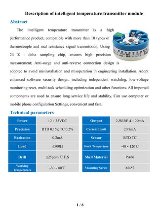
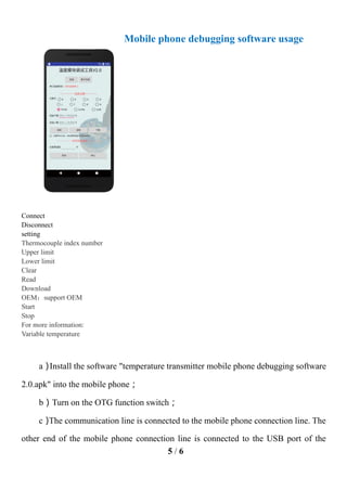
This document summarizes an intelligent temperature transmitter module. It measures temperature using thermocouples and resistance temperature detectors, and transmits the temperature readings via a 4-20mA current loop. It can be configured using a computer or mobile phone application to set parameters like temperature limits. The module is powered by 12-35VDC and has inputs for various sensor types, precision of 0.1-0.2% depending on sensor, and an operating temperature range of -30-80°C.


