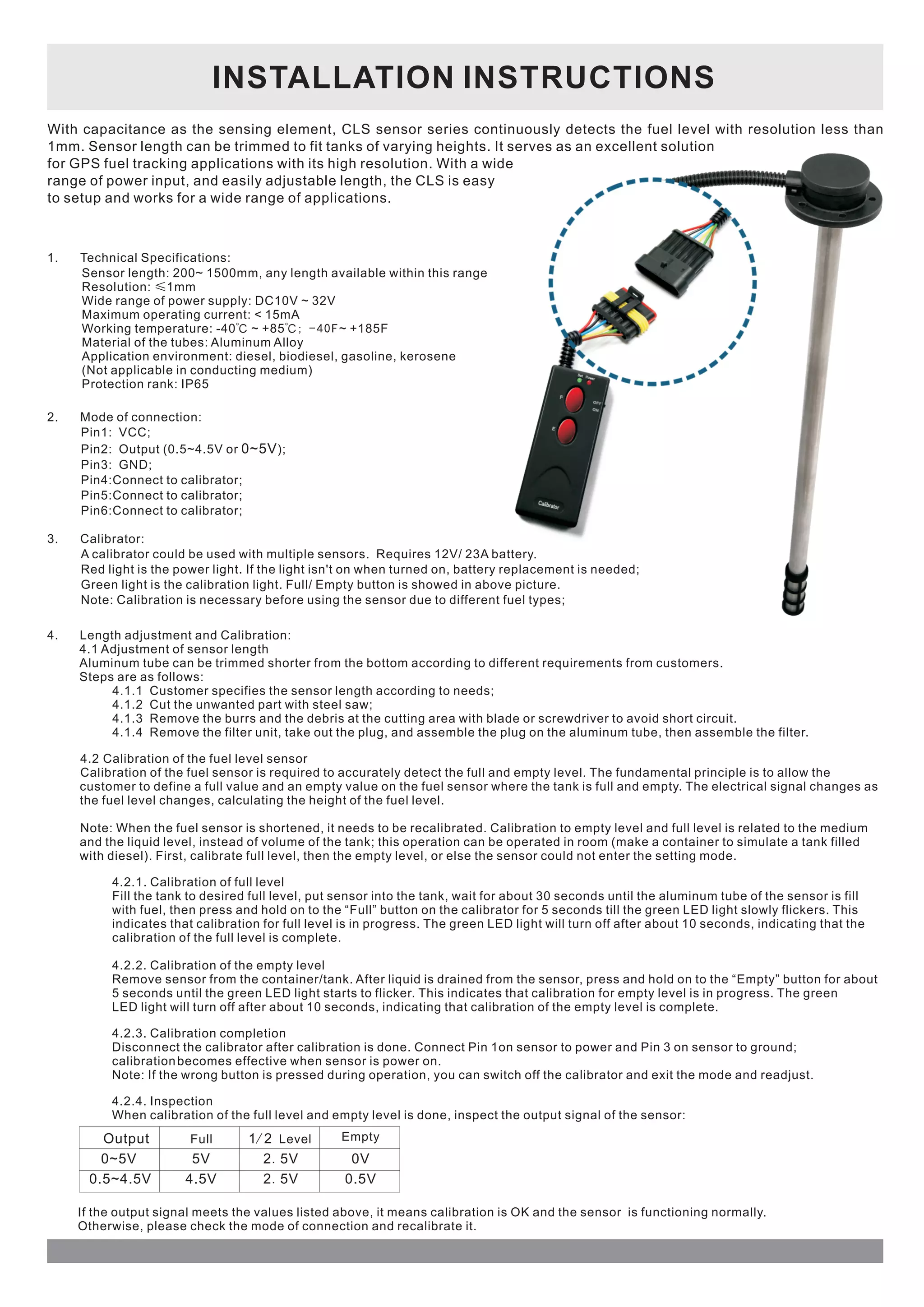
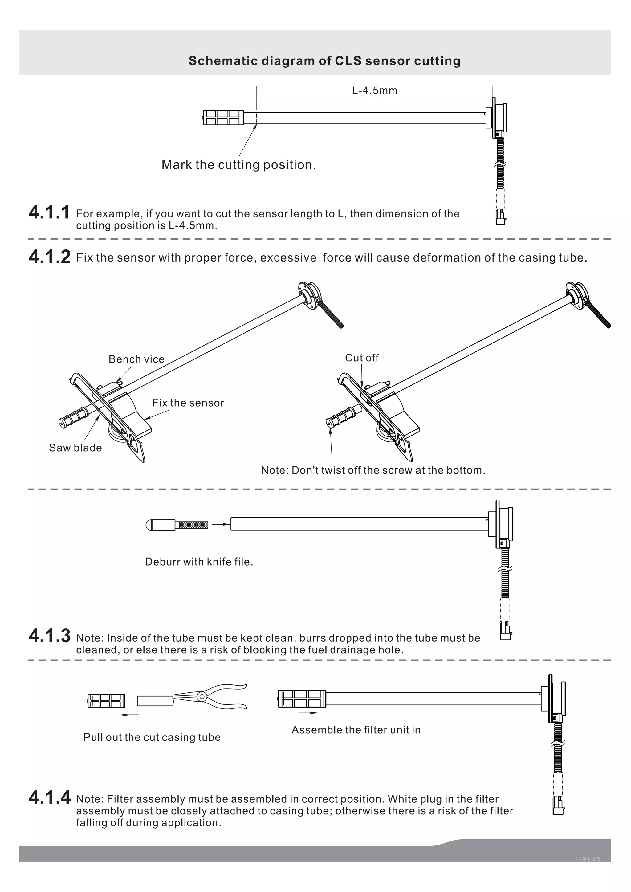
INSTALLATION INSTRUCTIONS 
With capacitance as the sensing element, CLS sensor series continuously detects the fuel level with resolution less than 
1mm. Sensor length can be trimmed to fit tanks of varying heights. It serves as an excellent solution 
for GPS fuel tracking applications with its high resolution. With a wide 
range of power input, and easily adjustable length, the CLS is easy 
to setup and works for a wide range of applications. 
1. Technical Specifications: 
Sensor length: 200~ 1500mm, any length available within this range 
Resolution: ≤1mm 
Wide range of power supply: DC10V ~ 32V 
Maximum operating current: < 15mA 
Working temperature: -40℃ ~ +85℃; - 4 0 F ~ +185F 
Material of the tubes: Aluminum Alloy 
Application environment: diesel, biodiesel, gasoline, kerosene 
(Not applicable in conducting medium) 
Protection rank: IP65 
2. Mode of connection: 
Pin1: VCC; 
Pin2: Output (0.5~4.5V or 0~5V 
); 
Pin3: GND; 
Pin4:Connect to calibrator; 
Pin5:Connect to calibrator; 
Pin6:Connect to calibrator; 
3. Calibrator: 
A calibrator could be used with multiple sensors. Requires 12V/ 23A battery. 
Red light is the power light. If the light isn't on when turned on, battery replacement is needed; 
Green light is the calibration light. Full/ Empty button is showed in above picture. 
Note: Calibration is necessary before using the sensor due to different fuel types; 
4. Length adjustment and Calibration: 
4.1 Adjustment of sensor length 
Aluminum tube can be trimmed shorter from the bottom according to different requirements from customers. 
Steps are as follows: 
4.1.1 Customer specifies the sensor length according to needs; 
4.1.2 Cut the unwanted part with steel saw; 
4.1.3 Remove the burrs and the debris at the cutting area with blade or screwdriver to avoid short circuit. 
4.1.4 Remove the filter unit, take out the plug, and assemble the plug on the aluminum tube, then assemble the filter. 
4.2 Calibration of the fuel level sensor 
Calibration of the fuel sensor is required to accurately detect the full and empty level. The fundamental principle is to allow the 
customer to define a full value and an empty value on the fuel sensor where the tank is full and empty. The electrical signal changes as 
the fuel level changes, calculating the height of the fuel level. 
Note: When the fuel sensor is shortened, it needs to be recalibrated. Calibration to empty level and full level is related to the medium 
and the liquid level, instead of volume of the tank; this operation can be operated in room (make a container to simulate a tank filled 
with diesel). First, calibrate full level, then the empty level, or else the sensor could not enter the setting mode. 
4.2.1. Calibration of full level 
Fill the tank to desired full level, put sensor into the tank, wait for about 30 seconds until the aluminum tube of the sensor is fill 
with fuel, then press and hold on to the “Full” button on the calibrator for 5 seconds till the green LED light slowly flickers. This 
indicates that calibration for full level is in progress. The green LED light will turn off after about 10 seconds, indicating that the 
calibration of the full level is complete. 
4.2.2. Calibration of the empty level 
Remove sensor from the container/tank. After liquid is drained from the sensor, press and hold on to the “Empty” button for about 
5 seconds until the green LED light starts to flicker. This indicates that calibration for empty level is in progress. The green 
LED light will turn off after about 10 seconds, indicating that calibration of the empty level is complete. 
4.2.3. Calibration completion 
Disconnect the calibrator after calibration is done. Connect Pin 1on sensor to power and Pin 3 on sensor to ground; 
calibration becomes effective when sensor is power on. 
Note: If the wrong button is pressed during operation, you can switch off the calibrator and exit the mode and readjust. 
4.2.4. Inspection 
When calibration of the full level and empty level is done, inspect the output signal of the sensor: 
Output 
0~5V 
0.5~4.5V 
Full 1/ 2 Level Empty 
5V 2. 5V 0V 
4.5V 2. 5V 0.5V 
If the output signal meets the values listed above, it means calibration is OK and the sensor is functioning normally. 
Otherwise, please check the mode of connection and recalibrate it.
1491-05 
4.1.1 
Mark the cutting position. 
L-4.5mm 
Cut off 
Note: Don't twist off the screw at the bottom. 
Assemble the filter unit in 
Bench vice 
Pull out the cut casing tube 
4.1.3 
4.1.4 
Deburr with knife file. 
4.1.2 
Fix the sensor 
Saw blade 
Schematic diagram of CLS sensor cutting 
For example, if you want to cut the sensor length to L, then dimension of the 
cutting position is L-4.5mm. 
Fix the sensor with proper force, excessive force will cause deformation of the casing tube. 
Note: Inside of the tube must be kept clean, burrs dropped into the tube must be 
cleaned, or else there is a risk of blocking the fuel drainage hole. 
Note: Filter assembly must be assembled in correct position. White plug in the filter 
assembly must be closely attached to casing tube; otherwise there is a risk of the filter 
falling off during application.

Capacitive Fuel Sensor Specification and Manual

  • 1.
    INSTALLATION INSTRUCTIONS Withcapacitance as the sensing element, CLS sensor series continuously detects the fuel level with resolution less than 1mm. Sensor length can be trimmed to fit tanks of varying heights. It serves as an excellent solution for GPS fuel tracking applications with its high resolution. With a wide range of power input, and easily adjustable length, the CLS is easy to setup and works for a wide range of applications. 1. Technical Specifications: Sensor length: 200~ 1500mm, any length available within this range Resolution: ≤1mm Wide range of power supply: DC10V ~ 32V Maximum operating current: < 15mA Working temperature: -40℃ ~ +85℃; - 4 0 F ~ +185F Material of the tubes: Aluminum Alloy Application environment: diesel, biodiesel, gasoline, kerosene (Not applicable in conducting medium) Protection rank: IP65 2. Mode of connection: Pin1: VCC; Pin2: Output (0.5~4.5V or 0~5V ); Pin3: GND; Pin4:Connect to calibrator; Pin5:Connect to calibrator; Pin6:Connect to calibrator; 3. Calibrator: A calibrator could be used with multiple sensors. Requires 12V/ 23A battery. Red light is the power light. If the light isn't on when turned on, battery replacement is needed; Green light is the calibration light. Full/ Empty button is showed in above picture. Note: Calibration is necessary before using the sensor due to different fuel types; 4. Length adjustment and Calibration: 4.1 Adjustment of sensor length Aluminum tube can be trimmed shorter from the bottom according to different requirements from customers. Steps are as follows: 4.1.1 Customer specifies the sensor length according to needs; 4.1.2 Cut the unwanted part with steel saw; 4.1.3 Remove the burrs and the debris at the cutting area with blade or screwdriver to avoid short circuit. 4.1.4 Remove the filter unit, take out the plug, and assemble the plug on the aluminum tube, then assemble the filter. 4.2 Calibration of the fuel level sensor Calibration of the fuel sensor is required to accurately detect the full and empty level. The fundamental principle is to allow the customer to define a full value and an empty value on the fuel sensor where the tank is full and empty. The electrical signal changes as the fuel level changes, calculating the height of the fuel level. Note: When the fuel sensor is shortened, it needs to be recalibrated. Calibration to empty level and full level is related to the medium and the liquid level, instead of volume of the tank; this operation can be operated in room (make a container to simulate a tank filled with diesel). First, calibrate full level, then the empty level, or else the sensor could not enter the setting mode. 4.2.1. Calibration of full level Fill the tank to desired full level, put sensor into the tank, wait for about 30 seconds until the aluminum tube of the sensor is fill with fuel, then press and hold on to the “Full” button on the calibrator for 5 seconds till the green LED light slowly flickers. This indicates that calibration for full level is in progress. The green LED light will turn off after about 10 seconds, indicating that the calibration of the full level is complete. 4.2.2. Calibration of the empty level Remove sensor from the container/tank. After liquid is drained from the sensor, press and hold on to the “Empty” button for about 5 seconds until the green LED light starts to flicker. This indicates that calibration for empty level is in progress. The green LED light will turn off after about 10 seconds, indicating that calibration of the empty level is complete. 4.2.3. Calibration completion Disconnect the calibrator after calibration is done. Connect Pin 1on sensor to power and Pin 3 on sensor to ground; calibration becomes effective when sensor is power on. Note: If the wrong button is pressed during operation, you can switch off the calibrator and exit the mode and readjust. 4.2.4. Inspection When calibration of the full level and empty level is done, inspect the output signal of the sensor: Output 0~5V 0.5~4.5V Full 1/ 2 Level Empty 5V 2. 5V 0V 4.5V 2. 5V 0.5V If the output signal meets the values listed above, it means calibration is OK and the sensor is functioning normally. Otherwise, please check the mode of connection and recalibrate it.
  • 2.
    1491-05 4.1.1 Markthe cutting position. L-4.5mm Cut off Note: Don't twist off the screw at the bottom. Assemble the filter unit in Bench vice Pull out the cut casing tube 4.1.3 4.1.4 Deburr with knife file. 4.1.2 Fix the sensor Saw blade Schematic diagram of CLS sensor cutting For example, if you want to cut the sensor length to L, then dimension of the cutting position is L-4.5mm. Fix the sensor with proper force, excessive force will cause deformation of the casing tube. Note: Inside of the tube must be kept clean, burrs dropped into the tube must be cleaned, or else there is a risk of blocking the fuel drainage hole. Note: Filter assembly must be assembled in correct position. White plug in the filter assembly must be closely attached to casing tube; otherwise there is a risk of the filter falling off during application.