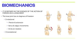
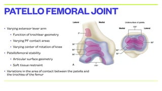
The document discusses total knee arthroplasty, a surgical procedure aimed at relieving pain and correcting deformities in the knee joint. It encompasses various aspects such as knee anatomy, mechanics, types of knee prostheses, materials used, and contraindications for surgery. Additionally, it outlines the complexities of knee kinematics and the considerations in choosing implants for knee replacement surgeries.

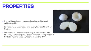
![• IT IS ULTRA HIGH MOLECULAR WEIGHT
POLYETHYLENE
• It is a subset of the thermoplastic polyethylene
• It has extremely long chains, with a high molecular mass 1]
which serves to transfer load more effectively to the
polymer backbone by strengthening intermolecular
interactionsresults in a very tough material, with the
highest impact strength
TIBIALINSERT](https://image.slidesharecdn.com/tkrfinal-250119181703-c511bf39/85/Total-Knee-Replacement-final-ppt-FINAL-pdf-30-320.jpg)
![• Highly cross-linked UHMWPE materials were clinically introduced in 1998
• These new materials are cross-linked with gamma or electron beam radiation (50–105 kGy)
and then thermally processed to improve their oxidation resistance
• In 2007, manufacturers started incorporating anti-oxidants into UHMWPE for hip and knee
arthroplasty bearing surfaces.[1]
• Vitamin E (a-tocopherol) is the most common anti-oxidant used
• The anti-oxidant helps quench free radicals that are introduced during the irradiation process,
imparting improved oxidation resistance to the UHMWPE without the need for thermal
treatment
VARIANTS](https://image.slidesharecdn.com/tkrfinal-250119181703-c511bf39/85/Total-Knee-Replacement-final-ppt-FINAL-pdf-32-320.jpg)


![• THROMBOEMBOLISM
• The development of deep vein thrombosis (DVT) with the potential to propagate a potentially
lethal pulmonary embolus (PE) is one of the most feared complications of TKA.
• The reported incidence of DVT following TKA without prophylaxis ranges from 40 to 88
percent [6-8].
• The incidences of asymptomatic PE, symptomatic PE, and mortality range from 10 to 20
percent, 0.5 to 3 percent, and up to 2 percent, respectively.
EARLYCOMPLICATIONS](https://image.slidesharecdn.com/tkrfinal-250119181703-c511bf39/85/Total-Knee-Replacement-final-ppt-FINAL-pdf-114-320.jpg)


![COMPUTER ASSISTED ORTHOPAEDICS SURGERY [Autosaved] (1).pptx](https://cdn.slidesharecdn.com/ss_thumbnails/computerassistedorthopaedicssurgeryautosaved1-250211145313-9f76e6d8-thumbnail.jpg?width=640&height=640&fit=bounds)


