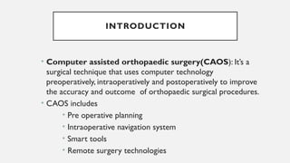
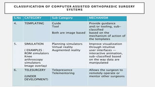
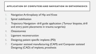
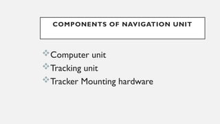
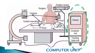
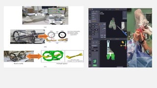
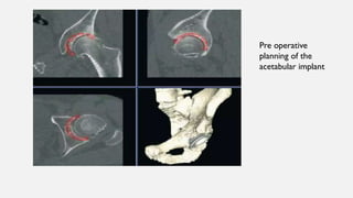
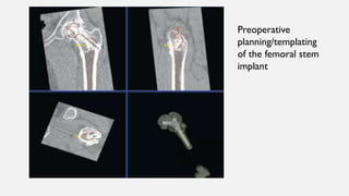
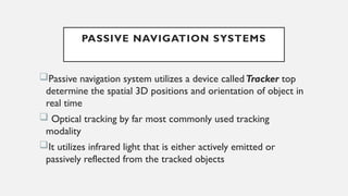
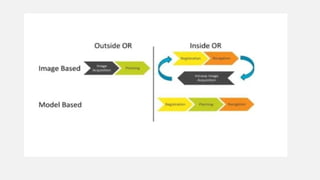
COMPUTER ASSISTED
ORTHOPAEDICS SURGERY
MODERATOR: DR. SIVAPRASAD
PROFESSOR OF DEPARTMENT OF ORTHOPAEADICS
PRESENTOR:DR.SHEKHER MISRA
INTRODUCTION
• Computer assisted orthopaedic surgery(CAOS): It’s a
surgical technique that uses computer technology
preoperatively, intraoperatively and postoperatively to improve
the accuracy and outcome of orthopaedic surgical procedures.
• CAOS includes
• Pre operative planning
• Intraoperative navigation system
• Smart tools
• Remote surgery technologies
• Computers augment orthopaedic surgery by taking
advantage of these fundamental characteristics
Geometric precision
Reproducibility
Perfect memory
Lack of fatigue
HISTORY
• ROBOT is a term used for a machine that
automatically carries out various tasks, requires little or
no assistance from outside and can be programmable
• ROBODOC was first robot which was introduced in
1992 for planning and performance of total hip
replacement
What does the NAVIGATION in CAOS means?
Where is my (anatomical) target?
How do I reach my target safely ?
Where am I anatomically?
Where and how shall I position my implant?
So navigation is a successor or natural evolution of frame based stereotaxy.
• Guide the surgeon to find the specific anatomical target
• Avoid areas of risk
• Offer intraoperative orientation in the absence of anatomical landmarks
• Optimal alignment of implants
• 3D measurement system
COMPONENTS OF NAVIGATION SYSTEM
DATA ACQUISITION
TRACKING
REGISTRATION
VISUALISATION
VALIDATION
REGISTRATION
It matches the virtual word of images
to the real word of the patient and
operating room environment.
Registration refers to the correlation
between CT or fluoroscopic images and
a fixed points on the patient’s anatomy
CONNECTION
It is referred to as TRACKERS.
Connection is the actual or virtual link between the
patient and the CAOS system.
The most type of connection is via light emitting diode
arrays placed in the instruments used in surgery, which
provide better than 0.3 mm accuracy
Used with 2 or more optical sensors in the operating
room allows adequate triangulation to calculate 3
dimensional localisation
CONNECTION
Combined with the data from registration, these
connection allow real time tracking of
instrumentation with patients anatomy
A direct connection is also used with robotic arms
to compensate instantly for relative motion between
the bone and robotic arm, will automatically stop the
system if movement of greater than 2mm is detected
SMART TOOLS
 Smart tools are the standard or customised
orthopaedic instruments whose 3D
characteristics have been taught to the CAOS
system to allow their display on a navigation
system
 This involves attaching a tracking array to the
handle of an instrument to confirm a
connection between the handle and the system
 The working end of the instrument is then
placed onto a known location, and a
REGISTRATION between the handle and
working tip of the instrument is made, including
the offset and the orientation device
CLASSIFICATION OF COMPUTER ASSISTED
ORTHOPAEDIC SURGERY SYSTEMS
CLASSIFICATION OF COMPUTER ASSISTED ORTHOPAEDIC SURGERY
SYSTEMS
APPLICATION OF COMPUTERS AND NAVIGATION IN ORTHOPAEDICS
1. Navigation Arthroplasty of Hip and Knee
2. Spinal stabilisation
3. Trajectory Navigation- drill guide application (Tumour biopsies, drill
and entry point placements in trauma surgeries)
4. Osteotomies
5. Ligament reconstruction
6. Designing patient specific implants (PSI)
7. Computer assisted manufacturing (CAM) and Computer assisted
Designing (CAD) of implants, prosthesis
COMPONENTS OF NAVIGATION UNIT
Computer unit
Tracking unit
Tracker Mounting hardware
MODE OF OPERATION OF NAVIGATION
• The tracking base unit receives and integrates the
signals from position sensor and the trackers.
• The computer integrates the signals from the base unit
with fluoroscopic radiography or CT images and
instrument models (registration), creates one or more
views for display(visualisation)
MODE OF OPERATION OF NAVIGATION
• The Navigated images are updated in real
time by the computer as the instruments
and anatomy move
• The tool calibration unit is used to obtain
geometric data of surgical tools fitted with
trackers, such as tool tips offset
• These geometric data are used to create
the instruments model for display
TRACKING
• Tracking requires a position sensors and one or more trackers
• The position sensor determines the spatial location of the trackers
at any given point of time
• By attaching trackers to surgical tools and bone structures, their
relative spatial position can continuously be followed and updated
in the computer display
• Trackers are rigidly mounted on tools and bones tracker mounting
jigs, which are the mechanical jig similar to screws and clamps
• When fluoroscopic radiographic images are used for navigation, the
computer unit is also connected to a C-arm and imports images
acquired with it
• The C-arm is usually fitted with own tracker to determine its relative
location with respect to the tracked objects and imaged anatomy
• Types of tracking technologies are available for medical application
• OPTICALTRACKING – commonly used
• MAGNETICTRACKING
TRACKING
OPTICAL TRACKING
• In optical tracking, the position sensor consists of two or more
optical cameras that detect light emitted or reflected by markers
• Each camera measures the distance of the markers from the
camera
• Because the base distance between the optical camera is known,
the position of the marker with respect to the camera base line
can be computed by method known as TRIANGULATION
FUNCTIONING OF TRACKER- 3
DIMENSIONAL CAPTURE ANALYSIS
MAGNETIC TRACKING
• It works by measuring variations of general magnetic field
• The position sensor consists of a magnet that generates a
uniform magnetic field and a sensor that measures its
phase and intensity variation
• Magnetic trackers are susceptible to the presence of
ferromagnetic objects and other disturbances in the EM
fields
REGISTRATION
• Registration is a process of establishing a common reference frame
between objects and images
• It is a prerequisite for creating a reliable image of the intraoperative
situation to accurately show the relative locations of operative landmark
and the surgical tools on the navigation system
• It is achieved by activating the trackers placed accurately on precise bony
landmarks using a handled devise.
• Once activated, trackers are captured by the sensors and the registration
of bony landmarks are incorporated in to the computer to template the
relevant anatomy and coordinate with preoperative radiographs
TYPES OF NAVIGATION SYSTEM
• Image based navigation
• Passive navigation system/Kinematic systems
• Active or Robotic navigation systems
IMAGE BASED NAVIGATION SYSTEM
Fluoroscopy based systems: 2D imaging
3D fluoroscopy
CT based Navigation
MRI based systems
GENERATIONS OF IMAGE ACQUISITION
MODALITY
•1st
generation- preoperative CT based
•2nd
generation- Fluoroscopy based 2D and 3D system
•3rd
generation- Intraoperative CT based
• CT based image system are almost ideal preoperative images modality for the
needs of CAOS, they present the bony anatomy with high resolution and good
contrast and without any geometrical distortions
• MRI comparatively suffers from poor hard tissue representation and sometimes
considerable geometric distortions compared to CT, Hence MRI are not widely
used in orthopaedic navigation nowadays
• X ray fluoroscopy has geometrical imprecision due to the fact that they capture
only 2D projections of a 3D structure when compared to CT
CT BASED NAVIGATION
With CT imaging , 3D image is created by reconstruction of the
transverse planar images acquired in a systematic and sequential order
from a source- receiver assembly that rotates in a circular pattern
Because of its relatively high accuracy and the bone imaging
characteristics CT scans are very suitable for surgical navigation,
especially in orthopaedics
MAIN ADVANTAGES OF CT- BASED SYSTEMS OVER
CONVENTIONAL FLUOROSCOPY
1. They provide axial and spatial, real time multi-image visualisation of bony
anatomy and surgical tools
2. They significantly reduce the use of fluoroscopy in the operating room
Pre-operative planning is typically done in three orthogonal cross-sectional views
made through the CT scan
Pre operative
planning of the
acetabular implant
Preoperative
planning/templating
of the femoral stem
implant
PASSIVE NAVIGATION SYSTEMS
Passive navigation system utilizes a device calledTracker top
determine the spatial 3D positions and orientation of object in
real time
 Optical tracking by far most commonly used tracking
modality
It utilizes infrared light that is either actively emitted or
passively reflected from the tracked objects
STEPS IN NAVIGATION
Data acquisition
Surgical planning
Registration of patient anatomy in OR
Use computer based navigation algorithm
Guide implant placement
VISUALISATION
• It creates updated images that show the location
of moving objects with respect to the anatomy
• The Navigation images are created by merging the
preoperative and intraoperative images with the
tools and bone location information
VALIDATION
• Validation is the task of verifying that the images
and data used for intraoperative navigation closely
correspond to the clinical situation
• Its essential step otherwise the data can mislead
the surgeon and yield unwanted results
• It is performed both before the surgery starts and
at key points during the surgery
CAOS- TOTAL KNEE
ARTHROPLASTY
• Although mechanical instruementation in traditional TKA
has significantly increased the accuracy and reliability with
which knee reconstructions area performed, still the
errors in implant and limb alignment continue to occur,
even when the procedure is performed by experienced
surgeons
• Computer assisted surgical techniques have been
developed to address the inherent limitations of
mechanical intruementation
CURRENTLY USED NAVIGATION SYSTEM
FOR TOTAL KNEE ARTHROPLASTY
1. CT free BasedTotal knee Navigation
arthroplasty-Passive Navigation
2. CT based Navigation Arthroplasty
3. Robotic or Active Navigation Arthroplasty
PASSIVE NAVIGATION IN TKR
• Optical localisation using infrared light is currently the
most widely used method of communication
• The tracking markers attached to surgical instruements
and reference frames attached to bony landmarks have
light emitting diode(LED) which send out light pulses
top camera (optical localizer)
• The camera system to which the light is sent consists
of 2 planar or 3 linear charge couple devices(CCD)that
are rigidly mounted onto a solid housing
SURGICAL TECHNIQUE- PASSIVE NAVIGATION TKR
• The initial step is the placement of the reference spatial
frames(with tracker attached) in the distal femur and proximal
tibia
• These are placed outside of the skin incision in a position that
avoids injury to neurovascular structures and allows clear
visualisation of the trackers by the camera
• Once the skin incision is made and the distal femur and proximal
tibia are exposed, anatomic landmarks critical for CAS guided
navigation are located
• The centre of femur head is determined using kinematic
registeration technique
• The hip is circumducted in a path guided by the visual cues
displayed upon the computer screen
• The centres of the knee and ankle joint can be established by using
kinematic or surface registeration technique or a combination of
both
OTHER ANATOMICAL LANDMARKS REGISTERED WITH A HANDHELD
CAS PROBE
The distal femur
The posterior condyle line
The anterior femoral cortex
The transepicondylar axis
The medial and lateral tibial articular surfaces
• Femoral and tibial stem
preparation done
• The CAS determination of
femoral implant size and
anterior and posterior
placement can be made using
anterior and posterior
referencing technique
Resection of distal femur
Computer interface indicating position
of distal femoral cutting block with
regard to frontal 0 degrees and sagittal 3
degrees anterior slope mechanical
alignment and depth of resection 9mm
Resection of proximal tibia:
Computer interface indicating position of proximal tibial
cutting block with regard to frontal 1degree varus and sagittal 0
degree mechanical alignment and depth from least involved tibial
surface 9mm
• Once the femoral and tibial resections are completed, a trial reduction is carried
out
• The polyethylene inserts that best, balances the knee in flexion and extension is
selected
• The navigation system is used to measure the final alignment of the extremity,
the amount of medial-lateral laxity in extension and flexion and the final range of
motion
• After the actual implants are inserted, the navigation system is used to measure
the final frontal and sagittal alignment of the extremity, the final medial-lateral
stability and final range of motion
CAOS IN HIP ARTHROPLASTY
• CAOS in Total hip arthroplasty is divided into using
Preoperative CT based(image based navigation) or
intraoperative mapping of osseous anatomical landmarks
on a generic model of pelvis(imageless navigation)
• CAOS in Total hip Arthroplasty improves accuracy in
achieving the planned acetabular cup positioning compared
to conventionalTHA
• Improves Precision and reduces outliers in restoring the
planned centre of hip rotation compared to conventional
THA
• Computer Navigation provides patient specific anatomical data with
recommendations for bone resection and optimal implant
positioning
• Robotic THA uses computer software to convert anatomical
information into a virtual patient specific 3D reconstruction of the
pelvis, which operating surgeon can calculate and plan optimal
implant positioning
• Depending on the degree of the control that the robotic device
provides the operating surgeons, robotic system classified as either
fully active or semi active
STAGES OF ROBOTIC THR
1. Preoperative CT scans of pelvis and proximal femur are
used to create a patient specific virtual 3D model of the
native hip anatomy.
This model accounts for pelvic orientation in
the axial, sagittal and coronal planes, which
enables accurate assessment and planning for
restoration of hip biomechanics
2. The surgeon uses this virtual 3D reconstruction to template
the optimal implant positions and sizes for achieving desired
bone coverage, restoration of hip biomechanics, component
version, component inclination and leg-length correction.
Software calculates the depth of acetabular reaming, femoral
osteotomy site and angle and component positioning
STAGES OF ROBOTIC THR
3. The surgeon intraoperatively maps the osseous anatomy of
acetabulum and proximal femur to establish bone geometry and
confirm pelvic position prior to bone resection
4. A robotic device is used to execute the planned bone resection and
guide final implant positioning with live onscreen changes in bone
coverage, implant inclination, implant version, offset any impingement
and leg length correction displayed throughout the procedure
STAGES OF ROBOTIC THR
COMPLICATIONS AND TECHNICAL PITFALLS DURING
NAVIGATION PROCEDURE
Loss of line of sight:
An obstructed view between the optical camera and the trackers
at all times is the basic requirement of optical navigation
Loss of line of sight occurs when the view between the optical
camera and one or more of the trackers is obstructed by the
surgeon or another member of surgical team, the patients body,
the fluoroscopic c arm or any other object in the vicinity of the
surgical field
Tool deliberation It occurs when the geometric data of the
tracked tool do not maych its actual geometry
Navigation image inaccuracy: inaccuracy of navigation images
is the mismatch between the displayed images and intraoperative
situation
Inaccuracy is the result of errors in the registration chain
COMPLICATIONS AND TECHNICAL PITFALLS DURING NAVIGATION
PROCEDURE
System robustness issues
Robustness is the ability of a system to perform its intended tasks
with a minimum number of failures over time
The more the robust the system, the more acceptable it will be to
the surgeon. Robustness depends on both software and hardware
components
COMPLICATIONS AND TECHNICAL PITFALLS DURING NAVIGATION
PROCEDURE
Shifting of the dynamic reference frame/Tracker positioning
Maintaining the rigid attachment between the bone tracker and the bone,
throughout the surgery is essential in order to guarantee registration accuracy
Shifting is usually the result of bone fixation loosening, poor jig fixation, or
unintentionally pushing or hitting the tracker and its monitoring jig
COMPLICATIONS AND TECHNICAL PITFALLS DURING NAVIGATION
PROCEDURE
HYBRID SYSTEMS
NAVIGATION +
ROBOT
It is a hand held Robot
showing here
TYPES OF ROBOTIC SURGERY SYSTEMS
• Haptic (Tactile or surgeon guided)
• Autonomous system
Haptic system requires surgeon’s continuous input for efficiently performing and
completing surgery. Surgeon uses or drives Robot to perform an operation.
While,Autonomous system differ from haptic system by having more
independency.After the operative site is approached by the surgeon, he sets up
the machine and then engages the Robot, which completes the remaining task
without the help of a surgeon
CATEGORIES OF CAOS
• ACTIVE SYSTEM: in this entire procedure can be carried out
by robot with guidance of surgeon or independently.
• PASSIVE SYSTEM: in which the robot or computerized
program aids the surgeon in completing surgical procedure
Note: Regardless of active or passive system, CAOS requires a
mode of navigation to accurately carry out the procedure
ADVANTAGES OF ROBOTIC SURGERY
Minimal invasive surgery(MIS) is possible
Implants can be placed more accurately
Radiologically, improved alignment of
extremities
HAPTIC ROBOTIC SYSTEM
• ROBOTIC ARM INTERACTIVE ORTHOPEDIC
SYSTEM(RIO,MAKO SURGICAL CORPORATION.)
• Its commercially available tactile system for
Unicondylar Knee Replacement(UKR)
• It is an tactile system so surgeons participation is
must to complete the UKR
• Preoperatively, CT scan of knee is required with
which 3D computer model of the knee is
prepared which forms the basis of planning
• Based on this, surgeon will mark the bony surfaces of femur and
tibia during operation
• Surgeon merges the preoperative model into active anatomy of
the knee.
• After taking the knee through full range of motion, the flexion
extension gap assessed, component size and implant placement
finalized and a cutting zone is created for the Robot.
• Preoperative planning and templating process forms the base for
the systems algorithm
• By viewing the 3D model of the knee on the monitor, the
surgeon accurately manipulates the burr and resects the bone.
• Forced controlled tip of the rotating burr cannot resect the bone
outside the predefined cutting space.
• The safety system automatically stops the Burr when goes beyond
the cutting zone
Other Robotic systems for UKR is ACROBOT SYSTEM
ACROBOT SYSTEM MAKO RIO
AUTONOMUS ROBOTIC SYSTEMS
They differ from Tactile system by their independency, It do not require surgeon’s
assistance
 Defined on the preset program they carry on and complete the surgery on their own
ROBODOC(California): It is autonomus robotic system developed in 1980 and taken
into surgical practice in 1992 for THA.
Other examples of AUTONOMUS ROBOTIC SYSTEM
MINI BONE ATTACHED ROBOTIC SYSTEM(MBARS):Pittsburgh, Pensylvania
Praxiteles: developed in France
MAKOTHRVIDEO
MAKO TKR VIDEO
ROBOTIC SURGHERY:PITFALLS AND LIMITATIONS
The setup required for performing robotic surgery is a expensive
It constantly requires software upgradations and caliberations, making it
more expensive
Superiority and cost efficiency of robotic surgery in routine are yet to be
demonstrated by long term outcome studies
Robots can well identify the Bony anatomy, but itself cannot manage soft
tissue dissection
Currently, high quality level 1 studies including randomized control trails
are not available for the use of robotic surgery in clinical practice
The autonomous robotic system ROBODOC fell into disrepute because it
was associated with increased risk of blood loss, infection and neurological
damage perhaps increased rate of litigation
TELESURGERY
• Using robotics and/or other computer assisted devices
experienced surgeons can supervise, assist or perform surgical
procedures at remote location
• The 1st
telesurgery procedure was reported in 2001 whwn
surgeons from NewYork operated on 68 year lady in
Strasbourg, France for cholecystectomy by remotely
manipulating robotic tools
• In orthopaedics, telesurgery is not yet well developed
REFERENCES
1. Farber SH, Pacult MA, Godzik J,Walker CT,Turner JD, Porter RW and Uribe JS (2021) Robotics in
Spine Surgery:ATechnical Overview and Review of Key Concepts. Front. Surg. 8:578674. doi:
10.3389/fsurg.2021.578674
2. Kayani B, Konan S,Ayuob A,Ayyad S, Haddad FS.The current role of robotics in total hip arthroplasty.
EFORT Open Rev. 2019 Nov 1;4(11):618-625. doi: 10.1302/2058-5241.4.180088. PMID: 31754468;
PMCID: PMC6851528.
3. Zheng G, Nolte LP. Computer-Assisted Orthopedic Surgery: Current State and Future Perspective.
Front Surg. 2015 Dec 23;2:66. doi: 10.3389/fsurg.2015.00066. PMID: 26779486; PMCID: PMC4688391.
4. https://www.manchesterhipandknee.com/pdfs/outcomes-mako-total-knee-replacements.pdf
5. https://orthopaedicprinciples.com/2012/01/robotic-surgery-and-computer-navigation-in-orthopaedics/
6. Mavrogenis AF, Savvidou OD, Mimidis G, Papanastasiou J, Koulalis D, Demertzis N, Papagelopoulos PJ.
Computer-assisted navigation in orthopedic surgery. Orthopedics. 2013 Aug;36(8):631-42. doi:
10.3928/01477447-20130724-10. PMID: 23937743.
Thank you

COMPUTER ASSISTED ORTHOPAEDICS SURGERY [Autosaved] (1).pptx

  • 1.
    COMPUTER ASSISTED ORTHOPAEDICS SURGERY MODERATOR:DR. SIVAPRASAD PROFESSOR OF DEPARTMENT OF ORTHOPAEADICS PRESENTOR:DR.SHEKHER MISRA
  • 2.
    INTRODUCTION • Computer assistedorthopaedic surgery(CAOS): It’s a surgical technique that uses computer technology preoperatively, intraoperatively and postoperatively to improve the accuracy and outcome of orthopaedic surgical procedures. • CAOS includes • Pre operative planning • Intraoperative navigation system • Smart tools • Remote surgery technologies
  • 3.
    • Computers augmentorthopaedic surgery by taking advantage of these fundamental characteristics Geometric precision Reproducibility Perfect memory Lack of fatigue
  • 4.
    HISTORY • ROBOT isa term used for a machine that automatically carries out various tasks, requires little or no assistance from outside and can be programmable • ROBODOC was first robot which was introduced in 1992 for planning and performance of total hip replacement
  • 5.
    What does theNAVIGATION in CAOS means? Where is my (anatomical) target? How do I reach my target safely ? Where am I anatomically? Where and how shall I position my implant? So navigation is a successor or natural evolution of frame based stereotaxy. • Guide the surgeon to find the specific anatomical target • Avoid areas of risk • Offer intraoperative orientation in the absence of anatomical landmarks • Optimal alignment of implants • 3D measurement system
  • 6.
    COMPONENTS OF NAVIGATIONSYSTEM DATA ACQUISITION TRACKING REGISTRATION VISUALISATION VALIDATION
  • 7.
    REGISTRATION It matches thevirtual word of images to the real word of the patient and operating room environment. Registration refers to the correlation between CT or fluoroscopic images and a fixed points on the patient’s anatomy
  • 8.
    CONNECTION It is referredto as TRACKERS. Connection is the actual or virtual link between the patient and the CAOS system. The most type of connection is via light emitting diode arrays placed in the instruments used in surgery, which provide better than 0.3 mm accuracy Used with 2 or more optical sensors in the operating room allows adequate triangulation to calculate 3 dimensional localisation
  • 10.
    CONNECTION Combined with thedata from registration, these connection allow real time tracking of instrumentation with patients anatomy A direct connection is also used with robotic arms to compensate instantly for relative motion between the bone and robotic arm, will automatically stop the system if movement of greater than 2mm is detected
  • 11.
    SMART TOOLS  Smarttools are the standard or customised orthopaedic instruments whose 3D characteristics have been taught to the CAOS system to allow their display on a navigation system  This involves attaching a tracking array to the handle of an instrument to confirm a connection between the handle and the system  The working end of the instrument is then placed onto a known location, and a REGISTRATION between the handle and working tip of the instrument is made, including the offset and the orientation device
  • 12.
    CLASSIFICATION OF COMPUTERASSISTED ORTHOPAEDIC SURGERY SYSTEMS
  • 13.
    CLASSIFICATION OF COMPUTERASSISTED ORTHOPAEDIC SURGERY SYSTEMS
  • 14.
    APPLICATION OF COMPUTERSAND NAVIGATION IN ORTHOPAEDICS 1. Navigation Arthroplasty of Hip and Knee 2. Spinal stabilisation 3. Trajectory Navigation- drill guide application (Tumour biopsies, drill and entry point placements in trauma surgeries) 4. Osteotomies 5. Ligament reconstruction 6. Designing patient specific implants (PSI) 7. Computer assisted manufacturing (CAM) and Computer assisted Designing (CAD) of implants, prosthesis
  • 15.
    COMPONENTS OF NAVIGATIONUNIT Computer unit Tracking unit Tracker Mounting hardware
  • 19.
    MODE OF OPERATIONOF NAVIGATION • The tracking base unit receives and integrates the signals from position sensor and the trackers. • The computer integrates the signals from the base unit with fluoroscopic radiography or CT images and instrument models (registration), creates one or more views for display(visualisation)
  • 20.
    MODE OF OPERATIONOF NAVIGATION • The Navigated images are updated in real time by the computer as the instruments and anatomy move • The tool calibration unit is used to obtain geometric data of surgical tools fitted with trackers, such as tool tips offset • These geometric data are used to create the instruments model for display
  • 21.
    TRACKING • Tracking requiresa position sensors and one or more trackers • The position sensor determines the spatial location of the trackers at any given point of time • By attaching trackers to surgical tools and bone structures, their relative spatial position can continuously be followed and updated in the computer display • Trackers are rigidly mounted on tools and bones tracker mounting jigs, which are the mechanical jig similar to screws and clamps
  • 22.
    • When fluoroscopicradiographic images are used for navigation, the computer unit is also connected to a C-arm and imports images acquired with it • The C-arm is usually fitted with own tracker to determine its relative location with respect to the tracked objects and imaged anatomy • Types of tracking technologies are available for medical application • OPTICALTRACKING – commonly used • MAGNETICTRACKING TRACKING
  • 23.
    OPTICAL TRACKING • Inoptical tracking, the position sensor consists of two or more optical cameras that detect light emitted or reflected by markers • Each camera measures the distance of the markers from the camera • Because the base distance between the optical camera is known, the position of the marker with respect to the camera base line can be computed by method known as TRIANGULATION
  • 26.
    FUNCTIONING OF TRACKER-3 DIMENSIONAL CAPTURE ANALYSIS
  • 27.
    MAGNETIC TRACKING • Itworks by measuring variations of general magnetic field • The position sensor consists of a magnet that generates a uniform magnetic field and a sensor that measures its phase and intensity variation • Magnetic trackers are susceptible to the presence of ferromagnetic objects and other disturbances in the EM fields
  • 28.
    REGISTRATION • Registration isa process of establishing a common reference frame between objects and images • It is a prerequisite for creating a reliable image of the intraoperative situation to accurately show the relative locations of operative landmark and the surgical tools on the navigation system • It is achieved by activating the trackers placed accurately on precise bony landmarks using a handled devise. • Once activated, trackers are captured by the sensors and the registration of bony landmarks are incorporated in to the computer to template the relevant anatomy and coordinate with preoperative radiographs
  • 30.
    TYPES OF NAVIGATIONSYSTEM • Image based navigation • Passive navigation system/Kinematic systems • Active or Robotic navigation systems
  • 31.
    IMAGE BASED NAVIGATIONSYSTEM Fluoroscopy based systems: 2D imaging 3D fluoroscopy CT based Navigation MRI based systems
  • 32.
    GENERATIONS OF IMAGEACQUISITION MODALITY •1st generation- preoperative CT based •2nd generation- Fluoroscopy based 2D and 3D system •3rd generation- Intraoperative CT based
  • 33.
    • CT basedimage system are almost ideal preoperative images modality for the needs of CAOS, they present the bony anatomy with high resolution and good contrast and without any geometrical distortions • MRI comparatively suffers from poor hard tissue representation and sometimes considerable geometric distortions compared to CT, Hence MRI are not widely used in orthopaedic navigation nowadays • X ray fluoroscopy has geometrical imprecision due to the fact that they capture only 2D projections of a 3D structure when compared to CT
  • 34.
    CT BASED NAVIGATION WithCT imaging , 3D image is created by reconstruction of the transverse planar images acquired in a systematic and sequential order from a source- receiver assembly that rotates in a circular pattern Because of its relatively high accuracy and the bone imaging characteristics CT scans are very suitable for surgical navigation, especially in orthopaedics
  • 36.
    MAIN ADVANTAGES OFCT- BASED SYSTEMS OVER CONVENTIONAL FLUOROSCOPY 1. They provide axial and spatial, real time multi-image visualisation of bony anatomy and surgical tools 2. They significantly reduce the use of fluoroscopy in the operating room Pre-operative planning is typically done in three orthogonal cross-sectional views made through the CT scan
  • 37.
    Pre operative planning ofthe acetabular implant
  • 38.
  • 39.
    PASSIVE NAVIGATION SYSTEMS Passivenavigation system utilizes a device calledTracker top determine the spatial 3D positions and orientation of object in real time  Optical tracking by far most commonly used tracking modality It utilizes infrared light that is either actively emitted or passively reflected from the tracked objects
  • 41.
    STEPS IN NAVIGATION Dataacquisition Surgical planning Registration of patient anatomy in OR Use computer based navigation algorithm Guide implant placement
  • 42.
    VISUALISATION • It createsupdated images that show the location of moving objects with respect to the anatomy • The Navigation images are created by merging the preoperative and intraoperative images with the tools and bone location information
  • 44.
    VALIDATION • Validation isthe task of verifying that the images and data used for intraoperative navigation closely correspond to the clinical situation • Its essential step otherwise the data can mislead the surgeon and yield unwanted results • It is performed both before the surgery starts and at key points during the surgery
  • 45.
    CAOS- TOTAL KNEE ARTHROPLASTY •Although mechanical instruementation in traditional TKA has significantly increased the accuracy and reliability with which knee reconstructions area performed, still the errors in implant and limb alignment continue to occur, even when the procedure is performed by experienced surgeons • Computer assisted surgical techniques have been developed to address the inherent limitations of mechanical intruementation
  • 46.
    CURRENTLY USED NAVIGATIONSYSTEM FOR TOTAL KNEE ARTHROPLASTY 1. CT free BasedTotal knee Navigation arthroplasty-Passive Navigation 2. CT based Navigation Arthroplasty 3. Robotic or Active Navigation Arthroplasty
  • 47.
    PASSIVE NAVIGATION INTKR • Optical localisation using infrared light is currently the most widely used method of communication • The tracking markers attached to surgical instruements and reference frames attached to bony landmarks have light emitting diode(LED) which send out light pulses top camera (optical localizer) • The camera system to which the light is sent consists of 2 planar or 3 linear charge couple devices(CCD)that are rigidly mounted onto a solid housing
  • 48.
    SURGICAL TECHNIQUE- PASSIVENAVIGATION TKR • The initial step is the placement of the reference spatial frames(with tracker attached) in the distal femur and proximal tibia • These are placed outside of the skin incision in a position that avoids injury to neurovascular structures and allows clear visualisation of the trackers by the camera
  • 50.
    • Once theskin incision is made and the distal femur and proximal tibia are exposed, anatomic landmarks critical for CAS guided navigation are located • The centre of femur head is determined using kinematic registeration technique • The hip is circumducted in a path guided by the visual cues displayed upon the computer screen • The centres of the knee and ankle joint can be established by using kinematic or surface registeration technique or a combination of both
  • 52.
    OTHER ANATOMICAL LANDMARKSREGISTERED WITH A HANDHELD CAS PROBE The distal femur The posterior condyle line The anterior femoral cortex The transepicondylar axis The medial and lateral tibial articular surfaces
  • 55.
    • Femoral andtibial stem preparation done • The CAS determination of femoral implant size and anterior and posterior placement can be made using anterior and posterior referencing technique
  • 56.
    Resection of distalfemur Computer interface indicating position of distal femoral cutting block with regard to frontal 0 degrees and sagittal 3 degrees anterior slope mechanical alignment and depth of resection 9mm
  • 57.
    Resection of proximaltibia: Computer interface indicating position of proximal tibial cutting block with regard to frontal 1degree varus and sagittal 0 degree mechanical alignment and depth from least involved tibial surface 9mm
  • 58.
    • Once thefemoral and tibial resections are completed, a trial reduction is carried out • The polyethylene inserts that best, balances the knee in flexion and extension is selected • The navigation system is used to measure the final alignment of the extremity, the amount of medial-lateral laxity in extension and flexion and the final range of motion • After the actual implants are inserted, the navigation system is used to measure the final frontal and sagittal alignment of the extremity, the final medial-lateral stability and final range of motion
  • 62.
    CAOS IN HIPARTHROPLASTY
  • 63.
    • CAOS inTotal hip arthroplasty is divided into using Preoperative CT based(image based navigation) or intraoperative mapping of osseous anatomical landmarks on a generic model of pelvis(imageless navigation) • CAOS in Total hip Arthroplasty improves accuracy in achieving the planned acetabular cup positioning compared to conventionalTHA • Improves Precision and reduces outliers in restoring the planned centre of hip rotation compared to conventional THA
  • 64.
    • Computer Navigationprovides patient specific anatomical data with recommendations for bone resection and optimal implant positioning • Robotic THA uses computer software to convert anatomical information into a virtual patient specific 3D reconstruction of the pelvis, which operating surgeon can calculate and plan optimal implant positioning • Depending on the degree of the control that the robotic device provides the operating surgeons, robotic system classified as either fully active or semi active
  • 65.
    STAGES OF ROBOTICTHR 1. Preoperative CT scans of pelvis and proximal femur are used to create a patient specific virtual 3D model of the native hip anatomy. This model accounts for pelvic orientation in the axial, sagittal and coronal planes, which enables accurate assessment and planning for restoration of hip biomechanics
  • 66.
    2. The surgeonuses this virtual 3D reconstruction to template the optimal implant positions and sizes for achieving desired bone coverage, restoration of hip biomechanics, component version, component inclination and leg-length correction. Software calculates the depth of acetabular reaming, femoral osteotomy site and angle and component positioning STAGES OF ROBOTIC THR
  • 67.
    3. The surgeonintraoperatively maps the osseous anatomy of acetabulum and proximal femur to establish bone geometry and confirm pelvic position prior to bone resection 4. A robotic device is used to execute the planned bone resection and guide final implant positioning with live onscreen changes in bone coverage, implant inclination, implant version, offset any impingement and leg length correction displayed throughout the procedure STAGES OF ROBOTIC THR
  • 73.
    COMPLICATIONS AND TECHNICALPITFALLS DURING NAVIGATION PROCEDURE Loss of line of sight: An obstructed view between the optical camera and the trackers at all times is the basic requirement of optical navigation Loss of line of sight occurs when the view between the optical camera and one or more of the trackers is obstructed by the surgeon or another member of surgical team, the patients body, the fluoroscopic c arm or any other object in the vicinity of the surgical field
  • 74.
    Tool deliberation Itoccurs when the geometric data of the tracked tool do not maych its actual geometry Navigation image inaccuracy: inaccuracy of navigation images is the mismatch between the displayed images and intraoperative situation Inaccuracy is the result of errors in the registration chain COMPLICATIONS AND TECHNICAL PITFALLS DURING NAVIGATION PROCEDURE
  • 75.
    System robustness issues Robustnessis the ability of a system to perform its intended tasks with a minimum number of failures over time The more the robust the system, the more acceptable it will be to the surgeon. Robustness depends on both software and hardware components COMPLICATIONS AND TECHNICAL PITFALLS DURING NAVIGATION PROCEDURE
  • 76.
    Shifting of thedynamic reference frame/Tracker positioning Maintaining the rigid attachment between the bone tracker and the bone, throughout the surgery is essential in order to guarantee registration accuracy Shifting is usually the result of bone fixation loosening, poor jig fixation, or unintentionally pushing or hitting the tracker and its monitoring jig COMPLICATIONS AND TECHNICAL PITFALLS DURING NAVIGATION PROCEDURE
  • 77.
    HYBRID SYSTEMS NAVIGATION + ROBOT Itis a hand held Robot showing here
  • 78.
    TYPES OF ROBOTICSURGERY SYSTEMS • Haptic (Tactile or surgeon guided) • Autonomous system Haptic system requires surgeon’s continuous input for efficiently performing and completing surgery. Surgeon uses or drives Robot to perform an operation. While,Autonomous system differ from haptic system by having more independency.After the operative site is approached by the surgeon, he sets up the machine and then engages the Robot, which completes the remaining task without the help of a surgeon
  • 79.
    CATEGORIES OF CAOS •ACTIVE SYSTEM: in this entire procedure can be carried out by robot with guidance of surgeon or independently. • PASSIVE SYSTEM: in which the robot or computerized program aids the surgeon in completing surgical procedure Note: Regardless of active or passive system, CAOS requires a mode of navigation to accurately carry out the procedure
  • 80.
    ADVANTAGES OF ROBOTICSURGERY Minimal invasive surgery(MIS) is possible Implants can be placed more accurately Radiologically, improved alignment of extremities
  • 81.
    HAPTIC ROBOTIC SYSTEM •ROBOTIC ARM INTERACTIVE ORTHOPEDIC SYSTEM(RIO,MAKO SURGICAL CORPORATION.) • Its commercially available tactile system for Unicondylar Knee Replacement(UKR) • It is an tactile system so surgeons participation is must to complete the UKR • Preoperatively, CT scan of knee is required with which 3D computer model of the knee is prepared which forms the basis of planning
  • 82.
    • Based onthis, surgeon will mark the bony surfaces of femur and tibia during operation • Surgeon merges the preoperative model into active anatomy of the knee. • After taking the knee through full range of motion, the flexion extension gap assessed, component size and implant placement finalized and a cutting zone is created for the Robot. • Preoperative planning and templating process forms the base for the systems algorithm • By viewing the 3D model of the knee on the monitor, the surgeon accurately manipulates the burr and resects the bone.
  • 83.
    • Forced controlledtip of the rotating burr cannot resect the bone outside the predefined cutting space. • The safety system automatically stops the Burr when goes beyond the cutting zone Other Robotic systems for UKR is ACROBOT SYSTEM ACROBOT SYSTEM MAKO RIO
  • 84.
    AUTONOMUS ROBOTIC SYSTEMS Theydiffer from Tactile system by their independency, It do not require surgeon’s assistance  Defined on the preset program they carry on and complete the surgery on their own ROBODOC(California): It is autonomus robotic system developed in 1980 and taken into surgical practice in 1992 for THA. Other examples of AUTONOMUS ROBOTIC SYSTEM MINI BONE ATTACHED ROBOTIC SYSTEM(MBARS):Pittsburgh, Pensylvania Praxiteles: developed in France
  • 85.
  • 86.
  • 87.
    ROBOTIC SURGHERY:PITFALLS ANDLIMITATIONS The setup required for performing robotic surgery is a expensive It constantly requires software upgradations and caliberations, making it more expensive Superiority and cost efficiency of robotic surgery in routine are yet to be demonstrated by long term outcome studies Robots can well identify the Bony anatomy, but itself cannot manage soft tissue dissection Currently, high quality level 1 studies including randomized control trails are not available for the use of robotic surgery in clinical practice The autonomous robotic system ROBODOC fell into disrepute because it was associated with increased risk of blood loss, infection and neurological damage perhaps increased rate of litigation
  • 88.
    TELESURGERY • Using roboticsand/or other computer assisted devices experienced surgeons can supervise, assist or perform surgical procedures at remote location • The 1st telesurgery procedure was reported in 2001 whwn surgeons from NewYork operated on 68 year lady in Strasbourg, France for cholecystectomy by remotely manipulating robotic tools • In orthopaedics, telesurgery is not yet well developed
  • 89.
    REFERENCES 1. Farber SH,Pacult MA, Godzik J,Walker CT,Turner JD, Porter RW and Uribe JS (2021) Robotics in Spine Surgery:ATechnical Overview and Review of Key Concepts. Front. Surg. 8:578674. doi: 10.3389/fsurg.2021.578674 2. Kayani B, Konan S,Ayuob A,Ayyad S, Haddad FS.The current role of robotics in total hip arthroplasty. EFORT Open Rev. 2019 Nov 1;4(11):618-625. doi: 10.1302/2058-5241.4.180088. PMID: 31754468; PMCID: PMC6851528. 3. Zheng G, Nolte LP. Computer-Assisted Orthopedic Surgery: Current State and Future Perspective. Front Surg. 2015 Dec 23;2:66. doi: 10.3389/fsurg.2015.00066. PMID: 26779486; PMCID: PMC4688391. 4. https://www.manchesterhipandknee.com/pdfs/outcomes-mako-total-knee-replacements.pdf 5. https://orthopaedicprinciples.com/2012/01/robotic-surgery-and-computer-navigation-in-orthopaedics/ 6. Mavrogenis AF, Savvidou OD, Mimidis G, Papanastasiou J, Koulalis D, Demertzis N, Papagelopoulos PJ. Computer-assisted navigation in orthopedic surgery. Orthopedics. 2013 Aug;36(8):631-42. doi: 10.3928/01477447-20130724-10. PMID: 23937743.
  • 90.