CCS355 Neural Network & Deep Learning Unit II Notes with Question bank .pdf
1-Basics of Prestressed Concrete.pdforgs
1. PRESTRESSED CONCRETE
Basic concepts & Flexural Analysis
Dr. Qasim Shaukat Khan
Associate Professor
Civil Engineering Department
UET Lahore
Email: qasimkhan@uet.edu.pk
1
2. 1. Basic Concepts [Introduction, Stress Control by
Prestressing, Partial Prestressing, Prestressing Methods,
Changes in Prestress Force]
2. Materials [Introduction to High Strength Steel, Types of
Prestressing Steel, Stress-Strain Properties of Steel, Steel
Relaxation, Types of Concrete, Concrete in Uniaxial
Compression and Tension, Time dependent Deformation
of Concrete]
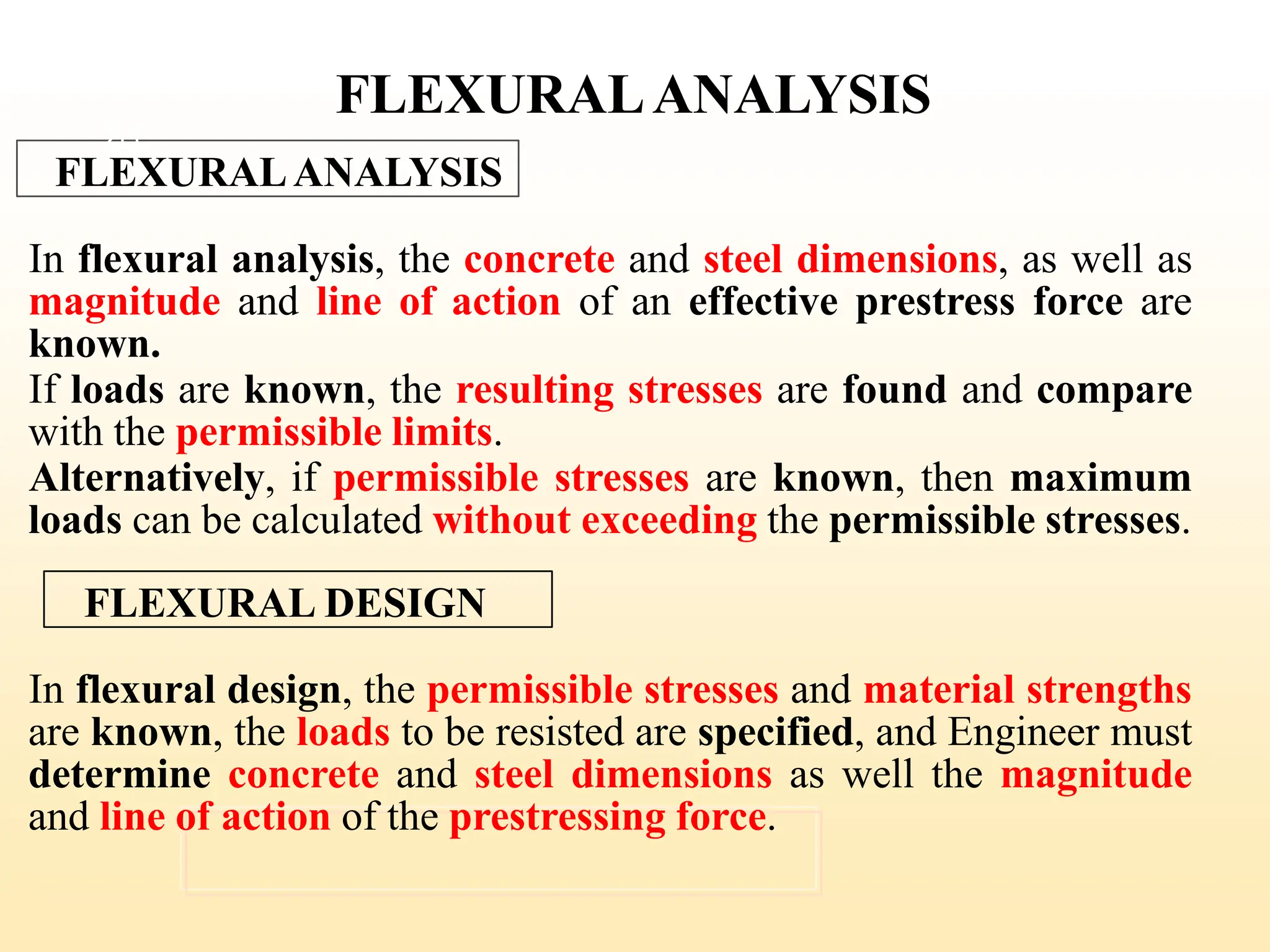
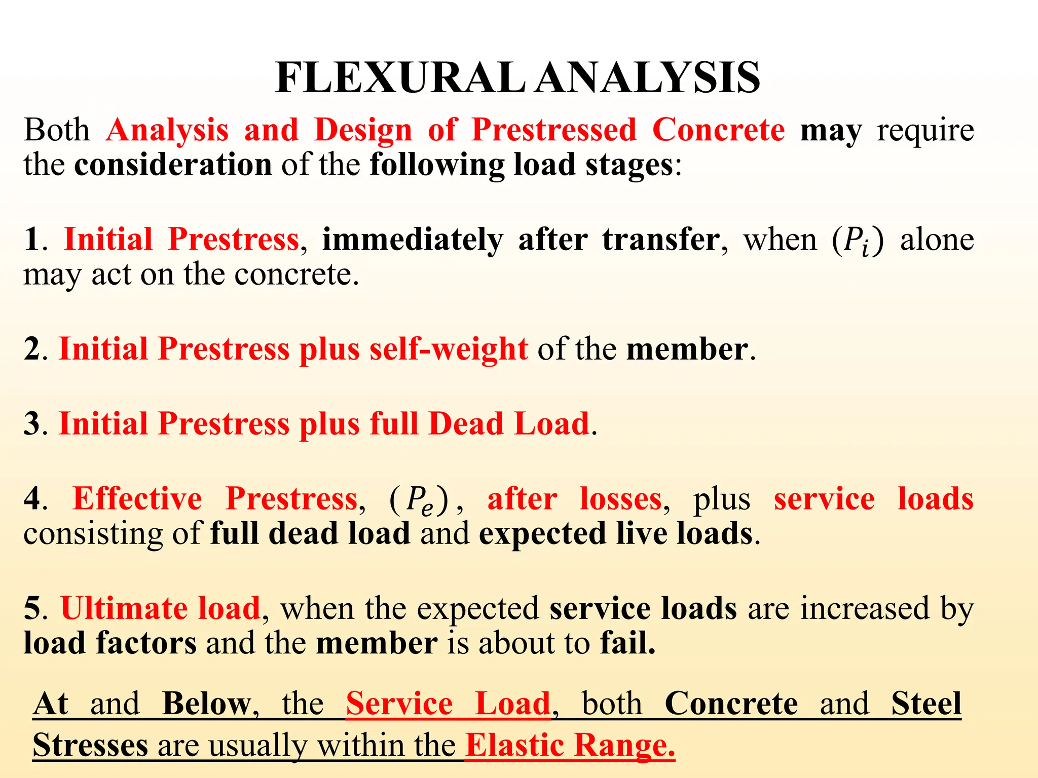
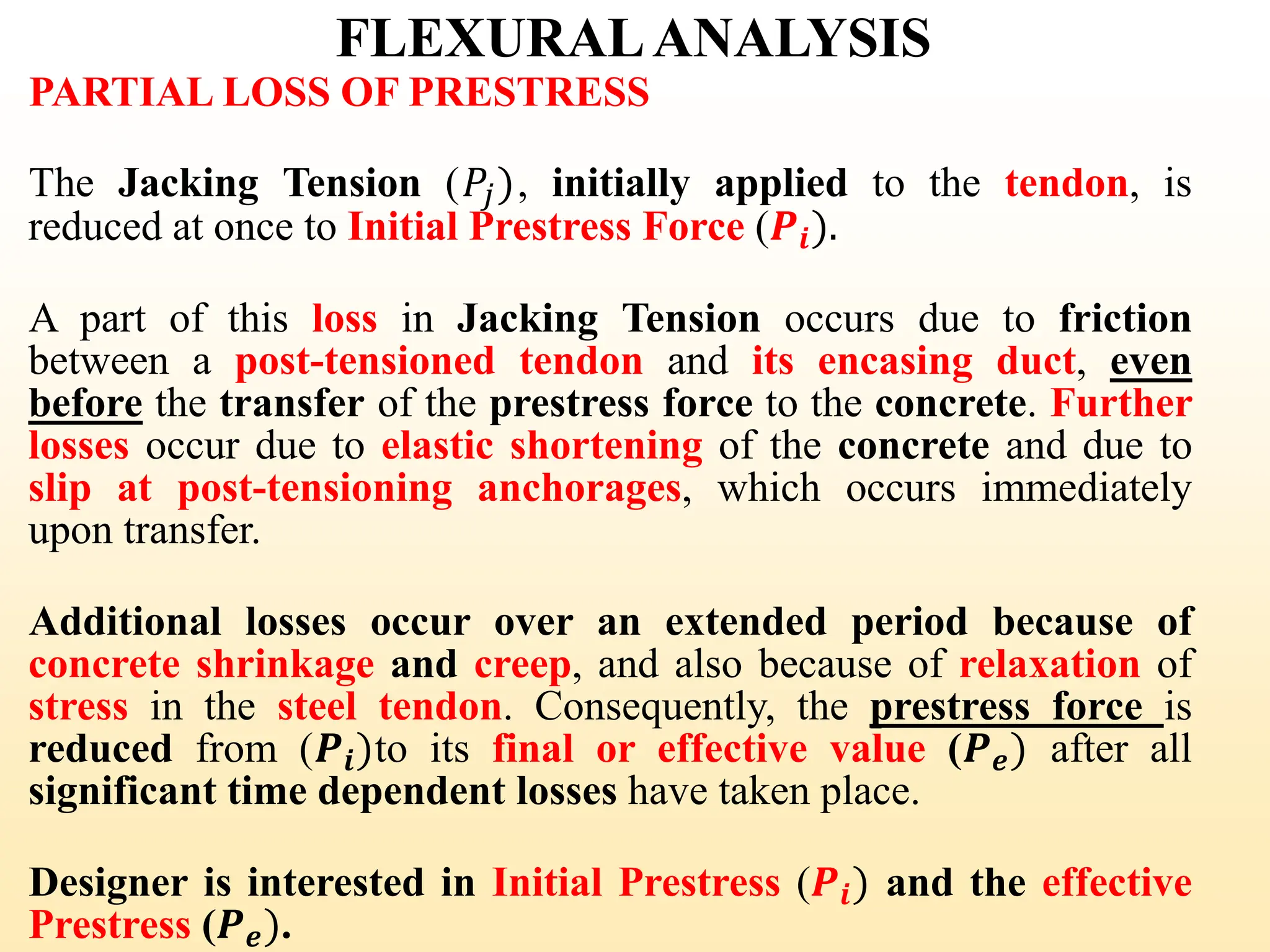
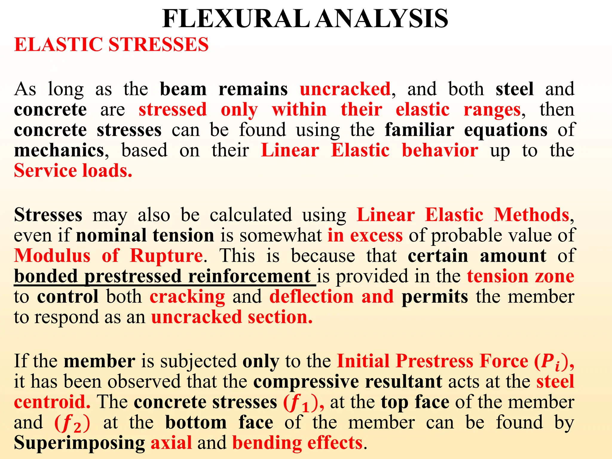
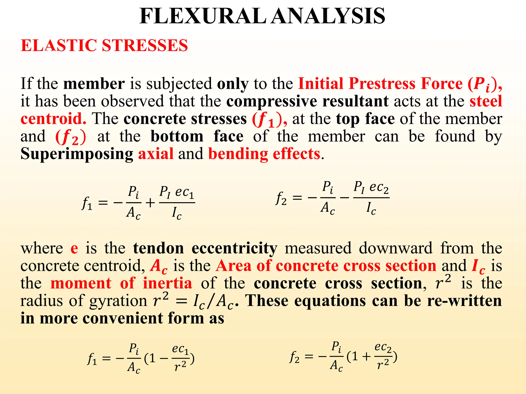
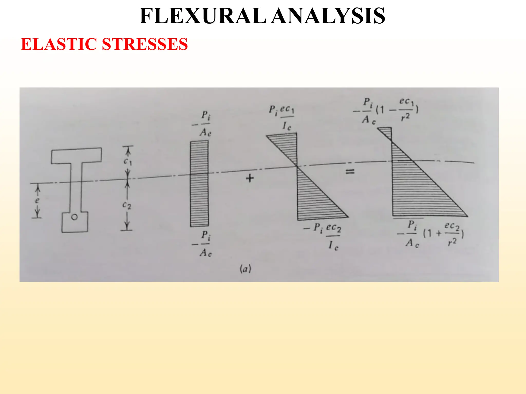
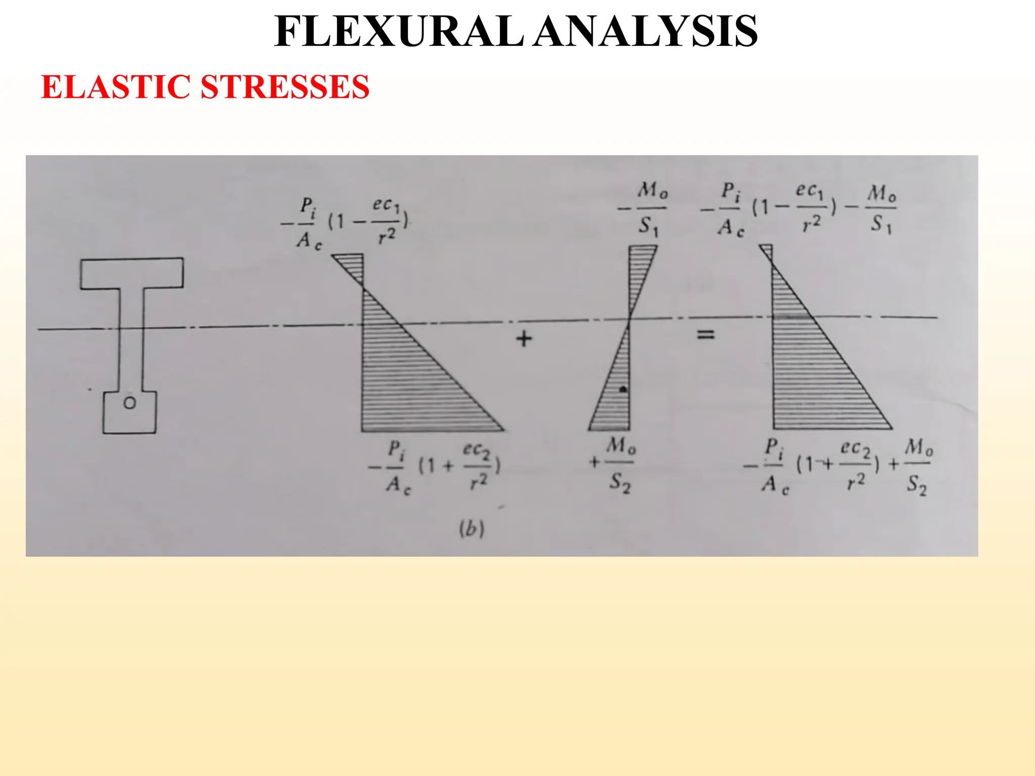
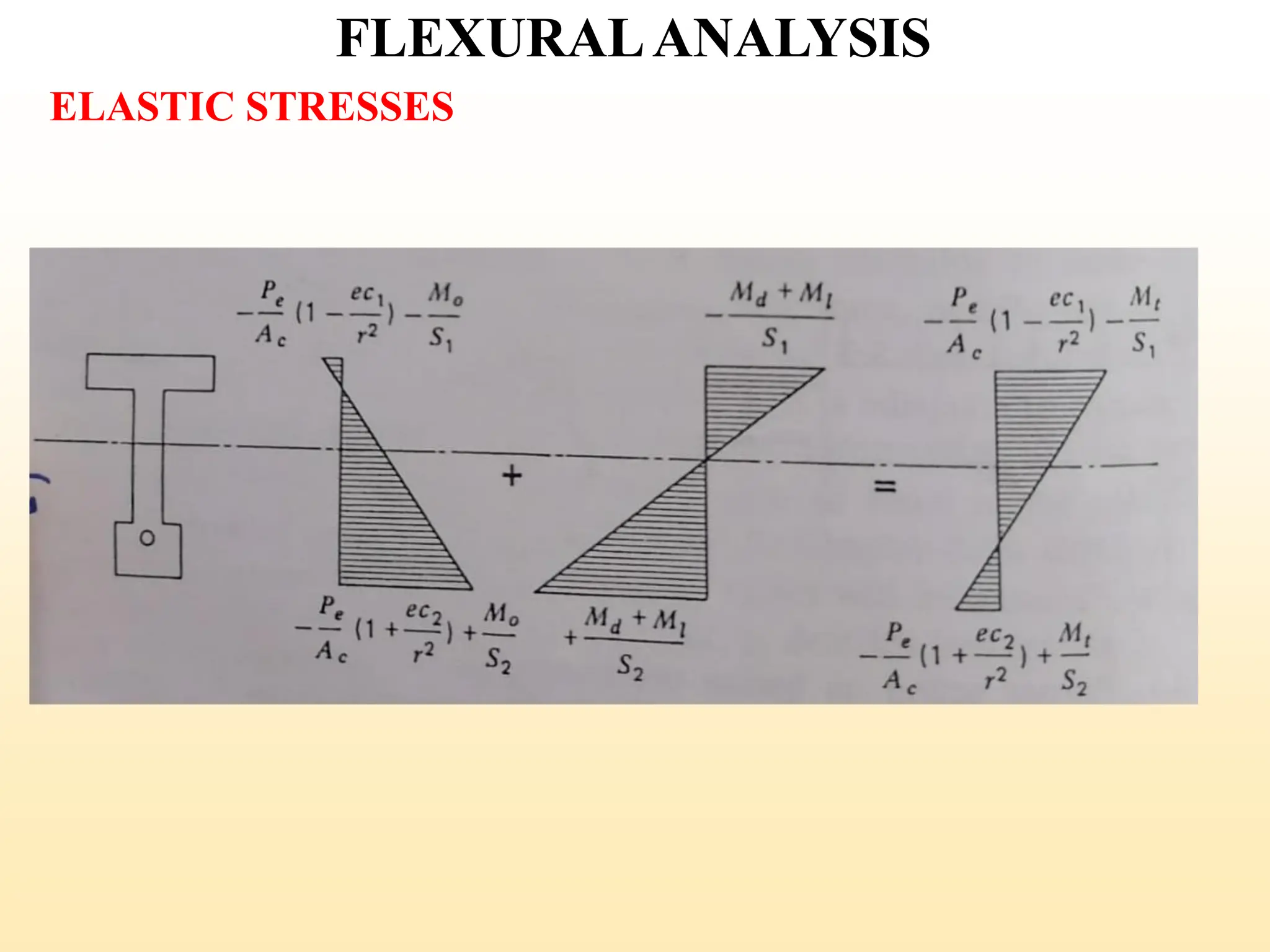
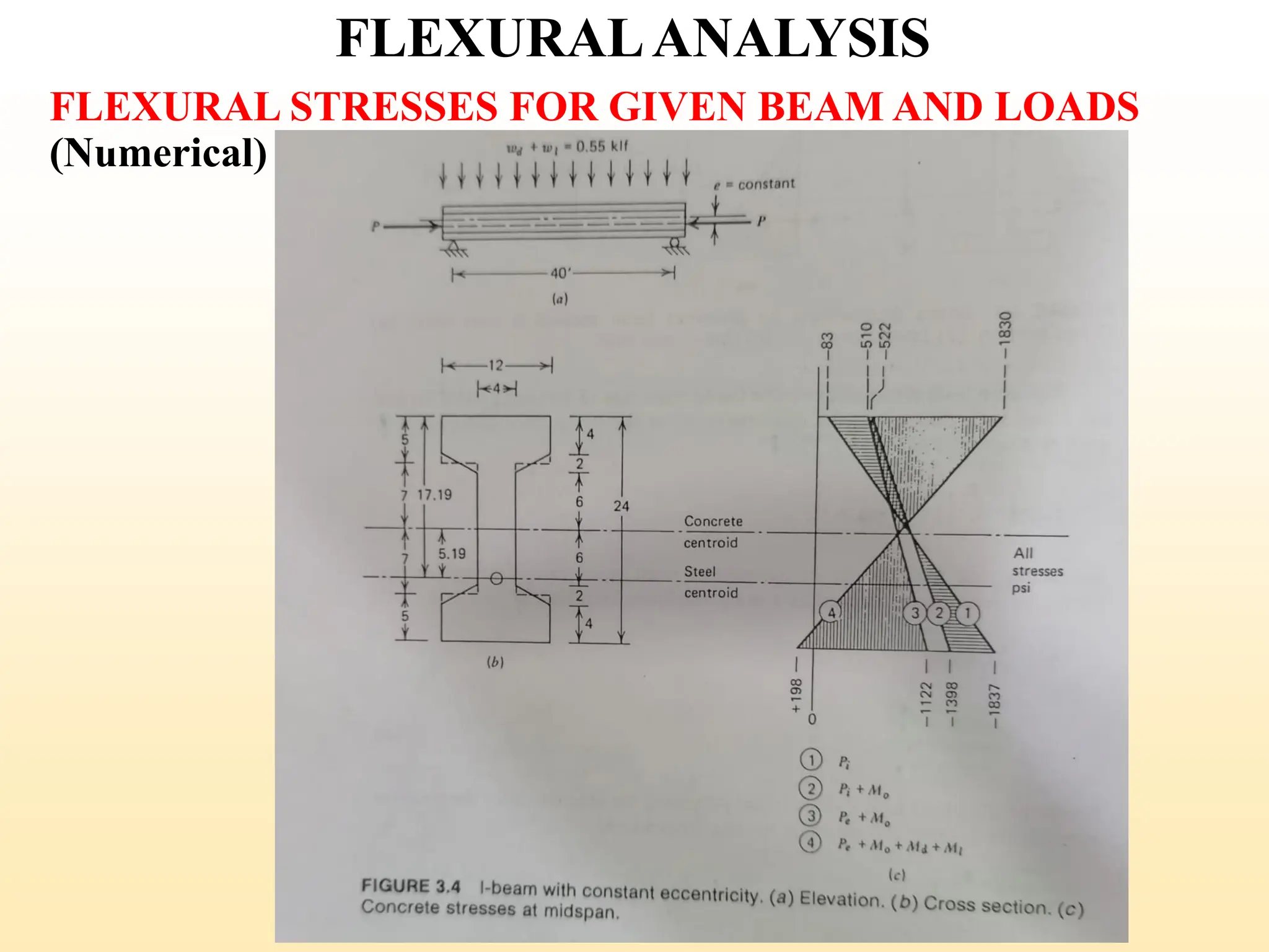
3. Flexural Analysis [Partial loss of Prestress Force, Elastic
Flexural Stresses in Uncracked Beams, Allowable
Flexural Stresses, Cracking Load, Flexural Strength
Analysis and ACI Design Equations, Partial Prestressing,
Elastic Flexural Stress after Cracking and Strength of
Partially Prestressed Beams]
LECTURE OUTLINE
2
3. 4. Flexural Design [Basis of Design, Flexural Design based on
Allowable Stresses, Shape Selection and Flexural Efficiency,
Load Balancing, Flexural design Based on Partial
Prestressing , Flexural Crack Control]
5. Shear and Torsion [Shear and Diagonal Tension in
Uncracked Beams, Diagonal Cracking Shear, Web
Reinforcement for Shear, Shear Design Criteria based on
ACI Criteria, Torsion in Concrete Structures, Torsion Design
of Prestressed Concrete]
6. Partial Loss of Prestress Force [Detailed Estimation of
Losses, Losses due to Friction, Anchorage Slip, Elastic
Shortening of Concrete, Creep and Shrinkage in Concrete,
Relaxation of Steel]
LECTURE OUTLINE
3
4. 7. Composite Beams [Types of Composite Construction, Load
Stages, Section Properties, Elastic Flexural Stresses, Flexural
Strength, Horizontal Shear Transfer, Shear and Diagonal
Tension]
8. Deflections [Basis for Calculations, Approximate Method
for Deflection Calculation, Deflection of Partially Prestressed
Beams, Allowable Deflections]
LECTURE OUTLINE
4
5. REFERENCES
Siddiqi, Z.A. (2016) Concrete Structures, Third Edition
(Part II), Help Publishers
Loo, Y-C and Chowdhury SH (2013) Reinforced and
Prestressed Concrete, Second edition, Cambridge Univ
Press.
Warner, R.F., Rangan, B.V., Hall, A.S. and
Faulkes, K.A. (1998) Concrete Structures, Addison
Wesley Longman
Gilbert, R.I. & Mickleborough, N.C. (1990) Design of
Prestressed Concrete, 1st Edn, Unwin Hyman.
Nilson, A. H. (1987) Design of Prestressed Concrete, Second
Edition, John Wiley & Sons
5
6. HISTORY
EUGENE FREYSINNET
A French engineer pioneered the
use of prestressed concrete in the
1930’s.
YVES GUYON, a student of
Freysinnet once summarized the
importance of the method saying:
“There is probably no structural
problem to which prestress cannot
provide a solution, and often a
revolutionary one.”
6
7. Reinforced concrete is one of the most widely used
structural materials in construction.
Due to the low tensile strength of concrete, steel bars
are introduced to carry all internal tensile forces.
Consider a simple reinforced concrete beam shown below:
w
REINFORCED CONCRETE
linear stresses
S
C
C
T
w
BEAM UNDER SERVICE LOADING
Section
Reinforcing bars
7
8. The external loads cause tension in the bottom fibers
which may lead to cracking, as shown on previous slide.
Most reinforced concrete beams are cracked due to Service
Loading.
Cracked cross-sections resist the applied moment by a
compressive force in the Concrete, C and a tensile force in
the Steel,T.
Tension reinforcement does not eliminate cracking and thus
does not prevent a loss of stiffness which cracking creates.
REINFORCED CONCRETE
8
9. PRESTRESSED CONCRETE
PRESTRESSED CONCRETE is a particular form of
reinforced concrete, which involves the application of an initial
compressive load (Pre-loading before the application of
Service Loads) on a structure to reduce or eliminate the
internal tensile forces / stresses and there by control or
eliminate cracking.
The compressive force is imposed and sustained by highly
tensioned steel reinforcement reacting on the concrete.
The concept of Prestressing of concrete is to introduce
sufficient axial precompression in beams so all tension in the
concrete was eliminated in the member at service load.
9
10. PRESTRESSED CONCRETE
A prestressed concrete beam section is considerably stiffer than
the equivalent cracked reinforced section.
Prestressing may also impose internal forces which
counterbalance external loads and may reduce or eliminate
deflection.
By varying the compressive prestress, the number and width of
cracks can be limited to the desired degree or zero deflection.
Full prestressing offers the possibility of complete elimination
of cracks at full service load, however, this results in large
camber.
Partial prestressing results in significant economy by reducing
the amount of prestressed reinforcement with some flexural
cracking within permissible limits at service loads.
10
11. METHODS OF PRESTRESSING
Prestressing is applied to a concrete member by highly tensioned
steel reinforcement (wire, strand, or bar) reacting on the concrete.
The high strength steel is most often tensioned using hydraulic
jacks. The tensioning operation may occur before or after the
concrete is cast and results in two classification:
(i) PRE - TENSIONED
Pretensioned prestressed concrete members are produced by
stretching the tendons between external anchorages before the
concrete is placed.
As fresh concrete hardens, it bonds to the steel. After the concrete
has attained the desired strength, the jacketing force is released,
and the force is transferred by bond from steel to concrete.
(ii) POST - TENSIONED
In Post tensioned prestressed concrete members, the tendons are
stressed after the concrete has hardened and achieved sufficient
strength, by jacketing against the concrete member itself.
11
13. PRE-TENSIONED
CONCRETE
The prestressing tendons are initially tensioned between
fixed abutments and anchored.
1
Formwork is constructed and the concrete is cast around the
highly stressed tendons and curved.
2
,
As the highly stressed steel attempts to contract the
concrete is compressed. Prestress is developed via bond
between the steel and concrete.
3
13
14. PRE-TENSIONED
CONCRETE
ADVANTAGES
✓Higher quality control can beachieved.
✓Lends itself to repetitive construction.
✓Decreased construction cycles
✓Pre-fabrication is advantageous for bridge girders
DISADVANTAGES
✓Elastic shortening of concrete and creep is high
✓High losses of prestress result
14
15. POST-TENSIONED
CONCRETE
The three stages of post-tensioned concrete are
shown above.
hollow duct
1. Concrete
cast and
cured uplift forces
TENSILE
FORCE
COMPRESSIVE
FORCE
2. Tendons stressed
and prestress
transferred
dead end
live end
3.Tendons
anchored and
duct grouted
15
16. POST-TENSIONED
CONCRETE
Formwork positioned and hollow duct fixed to desired
profile. Concrete cast and cured.
Tendons usually in place and unstressed.
1
Upon concrete reaching adequate strength, the
tendons are stressed.
2
Tendons are then anchored and the duct is grouted.
3
16
17. POST-TENSIONED
CONCRETE
ADVANTAGES
✓Members can be post-tensioned using relatively light and
portable hydraulic jacks
✓Attractive method for segmental construction of large span
bridges
✓Can be used for new or existing members using external
tendons
DISADVANTAGES
✓Ungrouted ducts as used in North America and Europe are
extremely dangerous, particularly during demolition
✓External tendons generally suffer large time-dependent
losses due to lack of bond between concrete and steel.
17
18. How prestressed concrete is made?
1
It all begins at the
prestressed
concrete plant.
2
This is called a
prestressing strand.
Made of high
strength steel, it
will soon be
embedded in
concrete.
3
The prestressing
strand is stretched
across the casting
bed. Tension will be
applied to the cable
before it's
surrounded by
concrete.
18
19. 4
Of course, cement,
sand, stone, and
water make up
concrete.
5
Special trucks bring
the concrete to the
casting bed where
the pouring begins.
Once the pouring is
complete, a tarp is
placed over the
form and heat is
applied to cure the
cement.
6
How prestressed concrete is made?
19
20. How prestressed concrete is made?
The prestressing
strands are cut and
the concrete form is
removed from the
casting bed.
7 8
The ends are cleaned
and the prestressing
strands are sealed with
a protective coating.
9
The end-product
is shipped to a
building site.
20
24. Precast concrete panels
Precast sandwich wall
panels are economical,
attractive, durable,
energy efficient and
very fast to install.
Buildings are enclosed in
days in any weather which
will considerately speed
up the construction process.
24
25. Post Tensioned (P-T) in Buildings
▪ Beams and slabs present good
opportunities for P-T
25
26. Advantages of P-T in Buildings
▪ Allows longer spans
▪ For spans >7m reduced overall costs
▪ Shallower slabs and beams
– Smaller floor to floorheight
▪ Deflection free slabs
▪ Waterproof concrete possible
▪ Early formwork stripping
▪ Less materials handling
▪ Reduced CO2 cost for PT concrete structure
26
27. Disadvantages of P-T
▪ Specialist contractor required to install
▪ High early strength concrete required
▪ Ducting and grouting activities
▪ More difficult to modify later
– Not easy to cut openings in P-T slab
▪ Anchorage design can be tricky
▪ Layout of strands and ducts requires greater planning
and design effort
27
28. FLEXURALANALYSIS
FLEXURALANALYSIS
In flexural analysis, the concrete and steel dimensions, as well as
magnitude and line of action of an effective prestress force are
known.
If loads are known, the resulting stresses are found and compare
with the permissible limits.
Alternatively, if permissible stresses are known, then maximum
loads can be calculated without exceeding the permissible stresses.
FLEXURAL DESIGN
In flexural design, the permissible stresses and material strengths
are known, the loads to be resisted are specified, and Engineer must
determine concrete and steel dimensions as well the magnitude
and line of action of the prestressing force.
28
29. FLEXURALANALYSIS
Both Analysis and Design of Prestressed Concrete may require
the consideration of the following load stages:
1. Initial Prestress, immediately after transfer, when (𝑃𝑖) alone
may act on the concrete.
2. Initial Prestress plus self-weight of the member.
3. Initial Prestress plus full Dead Load.
4. Effective Prestress, (𝑃𝑒), after losses, plus service loads
consisting of full dead load and expected live loads.
5. Ultimate load, when the expected service loads are increased by
load factors and the member is about to fail.
At and Below, the Service Load, both Concrete and Steel
Stresses are usually within the Elastic Range.
29
30. FLEXURALANALYSIS
PARTIAL LOSS OF PRESTRESS
The Jacking Tension (𝑃𝑗), initially applied to the tendon, is
reduced at once to Initial Prestress Force (𝑷𝒊).
A part of this loss in Jacking Tension occurs due to friction
between a post-tensioned tendon and its encasing duct, even
before the transfer of the prestress force to the concrete. Further
losses occur due to elastic shortening of the concrete and due to
slip at post-tensioning anchorages, which occurs immediately
upon transfer.
Additional losses occur over an extended period because of
concrete shrinkage and creep, and also because of relaxation of
stress in the steel tendon. Consequently, the prestress force is
reduced from (𝑷𝒊)to its final or effective value (𝑷𝒆) after all
significant time dependent losses have taken place.
Designer is interested in Initial Prestress (𝑷𝒊) and the effective
Prestress (𝑷𝒆).
30
31. FLEXURALANALYSIS
ELASTIC STRESSES
As long as the beam remains uncracked, and both steel and
concrete are stressed only within their elastic ranges, then
concrete stresses can be found using the familiar equations of
mechanics, based on their Linear Elastic behavior up to the
Service loads.
Stresses may also be calculated using Linear Elastic Methods,
even if nominal tension is somewhat in excess of probable value of
Modulus of Rupture. This is because that certain amount of
bonded prestressed reinforcement is provided in the tension zone
to control both cracking and deflection and permits the member
to respond as an uncracked section.
If the member is subjected only to the Initial Prestress Force (𝑷𝒊),
it has been observed that the compressive resultant acts at the steel
centroid. The concrete stresses (𝒇𝟏), at the top face of the member
and (𝒇𝟐) at the bottom face of the member can be found by
Superimposing axial and bending effects.
31
32. FLEXURALANALYSIS
ELASTIC STRESSES
If the member is subjected only to the Initial Prestress Force (𝑷𝒊),
it has been observed that the compressive resultant acts at the steel
centroid. The concrete stresses (𝒇𝟏), at the top face of the member
and (𝒇𝟐) at the bottom face of the member can be found by
Superimposing axial and bending effects.
𝑓1 = −
𝑃𝑖
𝐴𝑐
+
𝑃𝐼 𝑒𝑐1
𝐼𝑐
𝑓2 = −
𝑃𝑖
𝐴𝑐
−
𝑃𝐼 𝑒𝑐2
𝐼𝑐
where e is the tendon eccentricity measured downward from the
concrete centroid, 𝑨𝒄 is the Area of concrete cross section and 𝑰𝒄 is
the moment of inertia of the concrete cross section, 𝑟2
is the
radius of gyration 𝑟2
= Τ
𝐼𝑐 𝐴𝑐. These equations can be re-written
in more convenient form as
𝑓1 = −
𝑃𝑖
𝐴𝑐
(1 −
𝑒𝑐1
𝑟2
) 𝑓2 = −
𝑃𝑖
𝐴𝑐
(1 +
𝑒𝑐2
𝑟2 )
32
34. FLEXURALANALYSIS
ELASTIC STRESSES
Almost never would the Initial Prestress Force (𝑷𝒊) can act alone.
In most practical scenarios, with the tendon below the concrete
centroid, the beam will deflect upward because of the bending
moment caused by prestressing. It will then be supported by the
formwork or casting bed essentially at its ends, and the dead load
of the beam itself will cause moments (𝑀𝑂) to be superimposed
immediately.
Consequently, at the initial stage, immediately after transfer of
prestress force, the stresses in the concrete at the top and bottom
surfaces are
𝑓1 = −
𝑃𝑖
𝐴𝑐
1 −
𝑒𝑐1
𝑟2
−
𝑀𝑜
𝑆1
𝑓2 = −
𝑃𝑖
𝐴𝑐
1 +
𝑒𝑐2
𝑟2
+
𝑀𝑜
𝑆2
where 𝑴𝑶 is the bending moment resulting from the self-weight
of the member, and 𝑆1 = Τ
𝐼𝐶 𝐶1 and 𝑆2 = Τ
𝐼𝐶 𝐶2 are the Section
Moduli with respect to the top and bottom surfaces of the beam.
34
36. FLEXURALANALYSIS
ELASTIC STRESSES
Superimposed dead loads in addition to the self weight, may be
placed when the prestress force is still close to its initial value,
that is, before time dependent losses have occurred (Seldom stage).
Superimposed live loads are generally applied sufficiently late for
the greatest part of the loss of prestress to have occurred.
Next stage is, full service load stage, when the effective prestress
(𝑃𝑒), acts with the moments resulting from self weight (𝑀𝑂 ),
superimposed dead loads (𝑀𝑑) and superimposed live loads (𝑀𝑙).
The resulting stresses are
where 𝑴𝒕 = 𝑴𝑶 + 𝑴𝒅 + 𝑴𝒍
𝑓1 = −
𝑃𝑒
𝐴𝑐
1 −
𝑒𝑐1
𝑟2 −
𝑀𝑡
𝑆1
𝑓2 = −
𝑃𝑒
𝐴𝑐
1 +
𝑒𝑐2
𝑟2 −
𝑀𝑡
𝑆2
36
38. FLEXURALANALYSIS
FLEXURAL STRESSES FOR GIVEN BEAM AND LOADS
The simply supported I-beam carried a uniformly distributed
service dead and service live load totaling 8.02 kN/m over the
12.19 m span, in addition to its own weight. Normal concrete of
density 24 kN/m3 will be used. The beam will be pretensioned
using multiple seven wire strands, eccentricity is constant and
equal to 132 mm. The initial prestress force (𝑃𝑖) immediately after
transfer (after elastic shortening loss) is 752 kN. Time dependent
losses due to shrinkage, creep and relaxation are total 15% of the
initial prestress force. Find the concrete flexural stresses at
midspan and support sections under initial and final conditions.
For pretensioned beams using stranded cables, the difference
between sectional properties based on the gross and transformed
section is usually small. Accordingly, all calculations will be
based on the properties of gross concrete section.
38
M.O.I., Ic = 4.99 x 109 mm4; Concrete area, Ac = 114 x 103 mm3
Section Modulus, S1=S2=16.4 x 106 mm3; Radius of gyration r2=
44 x 102 mm2