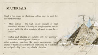
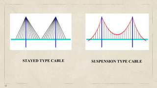
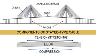
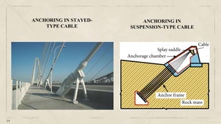
SlideShare a Scribd company logo
1 of 49
CABLE ANCHORING
AND GROUTING
CABLES
• A cable is A flexible structural component that offers no
resistance when compressed or bent in a curved shape.
Technically we can say cable has zero bending rigidity.
• It can only support tensile loading.
• Cables are often used in engineering structures for support and to
transmit load from one point to another when used to support
suspension roofs, bridges and trolley wheels, cables form the main
load carrying element in the structure.
Continued
 Being inextensible the cable has constant length before and after the load is
applied. as a result once the load is applied the geometry of cable remains
fixed.
The easiest structure type to think is a tension structure to resist only tensile
force and of these, the simplest are those which sustain only unidirectional
tension as represented by a cable or thin rod.
3
MATERIALS
Steel, nylon ropes or plasticated cables may be used for
different structures
• Steel Cables : The high tensile strength of steel
combined with the efficiency of simple tension, makes
a steel cable the ideal structural element to span large
distances.
• Nylon and plastics are suitable only for temporary
structures, spanning small distances.
other structural members like masts, compression rings,
arches or beams and compression struts may be of concrete
or steel preferably. Struts may also be of timber.
4
5
Types
6
Multi-wire tendon (Clifford, 1974)
Birdcaged multiwire Tendon (Jirovec,
1978)
High capacity shear dowel (Mathews
et al,1986)
Birdcaged strand (Hutchins et al,
1990)
Bulbed strand (Garford, 1990)
Ferruled strand (Windsor, 1990)
Coated single strand (Hunt & Askew,
1977)
Single strand (Hunt & Askew, 1977)
APPLICATION
7
8
1. Suspended type cable
2. Stayed type cable
9
• A suspension bridge is a type of bridge in which the deck (the load-bearing portion) is
hung below suspension cables on vertical suspenders.
• This type of bridge has cables suspended between towers, plus vertical suspender cables
that carry the weight of the deck below, upon which traffic crosses. This arrangement
allows the deck to be level or to are upward for additional clearance.
• The main type of force in a suspension bridge are tension in cables and compression in the
pillars.
SUSPENDED TYPE CABLE
10
• The suspension cables must be anchored at each end of the bridge, since any load
applied to the bridge is transformed into a tension in these main cables.
• The main cables continue beyond the pillars to deck-level supports, and further continue
to connections with anchors in the ground.
• The roadway is supported by vertical suspender cables or rods, called hangers,
• The bridge will usually have two smaller spans, running between either pair of pillars
and the highway, which may be supported by suspender cables or may use a truss bridge
to make this connection. In the latter case there will be very little are in the outboard
main cables.
Place your screenshot here
11
SUSPENSION TYPE CABLES
12
STAYED TYPE CABLE SUSPENSION TYPE CABLE
13
• Suspension bridges have a high strength to weight ratio. They are flexible (can also be
disadvantage) and can span long distances with no piers therefore good on very high places,
across water etc. and they require little access from below aiding construction.
• They can be very thin and therefore less visible.
• They have an elegant look. The area spanned by a suspension bridge is very long in proportion
to the amount of materials required to construct bridges.
ADVANTAGES
14
• Flexibility Disadvantages
Suspension bridges are flexible, which is an advantage until conditions became severe. Instability in
extremely turbulent conditions or during strong earthquakes may require temporary closure. In 1940,
high winds caused the Tacoma Narrows bridge, near Seattle. Washington, to collapse.
• Foundation Disadvantages
When built in soft ground, suspension bridges require extensive and expensive foundation work to
combat the effects of the heavy load on foundation towers.
• Heavy Loads
Flexibility also becomes a disadvantage when heavy, concentrated loads are involved. Suspension
bridges are not generally used for regional rail crossings that carry maximum weight loads, which adds
dangerous stress to the structure.
DISADVANTAGES
Assumption
 Cables are pure tension members.
 Used as:
1. Supports to suspension roofs.
2. Suspension bridge
3. Trolley bridge
 Self weight of cable is neglected in analysis
of structure.
 When used as cables for antennas or
transmission lines, weight is considered.
15
16
• A cable-stayed bridge has one or more towers (or pylons), from which cables support the bridge
deck diagonally
• There are two major classes of cable-stayed bridges: harp and fan. In the harp or parallel
design, the cables are nearly parallel so that the height of their attachment to the tower is
proportional to the distance from the tower to their mounting on the deck.
• In the fan design, the cables all connect to or pass over the top of the towers. The fan design is
structurally superior with minimum moment applied to the towers but for practical reasons the
modified fan is preferred especially where many cables are necessary. In the modified fan
arrangement the cables terminate near to the top of the tower but are spaced from each other
sufficient to allow better termination, improved environment protection, and good access to
individual cables for maintenance.
STAYED TYPE CABLE
Place your screenshot here
17
STAYED TYPE CABLES
18
COMPONENTS OF STAYED-TYPE CABLE
19
• In the cable-stayed bridge, the towers are the primary loud-bearing structures which transmit the
bridge loads to the ground.
• A cantilever approach is often used to support the bridge deck near the towers, but lengths further
from them are supported by cables running directly to the towers. This has the disadvantage,
compared to the suspension bridge, that the cables pull to the sides as opposed to directly up,
requiring the bridge deck to be stronger to resist the resulting horizontal compression loads; but has
the advantage of not requiring firm anchorages to resist the horizontal pull of the main cables of the
suspension bridge.
• By design all static horizontal forces of the cable-stayed bridge are balanced so that the supporting
towers do not tend to tilt or slide, needing only to resist horizontal forces from the live loads.
LOAD BEARING MECHANISM OF CABLE-STAYED
BRIDGES
20
DECK
CABLES
PYLONS
PILE CAP
PILES
SOIL
ANCHORING
21
22
• The cable-stayed deck is in compression, pulled towards the towers, and has to be stiff at all
stages of construction and use.
• A great advantage of the cable-stayed bridge is that it is essentially made of cantilevers, and
can be constructed by building out from the towers.
• cable-stayed bridges possess higher stiffness and display smaller deflections when compared
with suspension bridges
• Construction time is less for cable stayed bridges. Cable Stayed Bridges require less cables
ADVANTAGES OF CABLE-STAYED BRIDGE
23
• Base or substrate should have sufficient strength to take loads
• Anchoring can be done in hard concrete, loose concrete, stone masonry and brick masonry
• Anchors are available heaving high and low strength as per requirements
• Anchoring may require base plates, adhesives as per site requirements • now, many companies
provide anchors and
ANCHORING
24
ANCHORING IN STAYED-
TYPE CABLE
ANCHORING IN
SUSPENSION-TYPE CABLE
25
• Anchoring is required to join a component or member tο existing member. Normally, it is
done by breaking the substrate or existing surface, put some concrete and steel member
• In case, such arrangement has been forgotten, it is broken and redone
• In such case, anchoring technique can be used, and anchors fixed
CONSTRUCTION OF ANCHORING
Excavations and other engineering constructions in the ground are central to many civil and mining
projects.
Ground reinforcement includes among other methods, the techniques of ground anchoring, cable
bolting and rock bolting. Ground anchors tend to be longer with higher capacity, and are usually
associated with civil infrastructure projects.
Rock bolts tend to be shortest with lowest capacities .
Cable bolts are used in stability problems that lie between the two, and are commonly used in
mining engineering.
CABLE ANCHORING
• In the majority of moderately weak to strong rocks , rotary or rotary percussive open hole
drilling with air flush , followed by normal tremie grouting techniques , will achieve the required
grout/rock bond capacity.
• Where fissures or voids are detected by loss of flush, by water ingress, by water testing, or
inability to maintain a head of grout within the bore, then pre-grouting operations or alternatively
pressure grouting operations may be required.
• Normally cement grouts are injected but if fissures are known to be wide, sanded mixes may be
used.
• In coarse grained weak rocks similar techniques or alternatively rotary water flush drilling can
be used and in most conditions a reasonable anchorage capacity can be obtained.
ANCHORS IN ROCKS
28
• In order to enhance the capacity of the anchorage within the normal range of fixed lengths,
either under reaming or soil fracturing systems have been employed
• More recently, the single bore multiple anchor system has been allowed efficient use of non-
enhanced bore holes and attained loads of 3500kn.
• The fracturing of soil prior to tendon installation, generally involves a larger diameter steel
manchette, which after treatment remains in-situ.
• Treatment may be carried out over a 2 or 3 day period prior to tendon installation, by repeatedly
injecting grout through manchette valves at 1/2 m centers in the fixed length.
• The anchor tendon is then, after pre grouting treatment, installed and grouted within the large
tube.
• The tube must efficiently transfer the entire load from anchor tendon and internal grout to the
external grout and then into the ground.
• It must not exhibit creep losses and it must not in anyway degrade (by corrosion) in any way
such that there is a reduction in bond capacity or performance within the grout body which may
reduce the capacity of the anchor within its intended lifetime
ANCHORS IN CLAY
30
ANCHORS IN GRANULAR MATERIALS:
• Anchors are in the majority of instances
installed in granular deposits by drive drilling
with a knock-off bit or by use of duplex
drilling techniques.
• Drive drilling involves the percussion driving
of a strong casing with a conical lead bit
resulting lateral soil replacement and no flush
recovery. The lead bit is knocked off the casing
allowing tendon installation and pressure
grouting during withdrawal. There are
limitations in the depth penetrable.
GROUTING
32
34
Cable anchoring and grouting for cable tensioning

More Related Content

Similar to Cable anchoring and grouting for cable tensioning

CHapter 1 introduction to bridge design eng
CHapter 1 introduction to bridge design engCHapter 1 introduction to bridge design eng
CHapter 1 introduction to bridge design engabdi beder
 
stress ribbon bridge.pptx
stress ribbon bridge.pptxstress ribbon bridge.pptx
stress ribbon bridge.pptxSauravShahane
 
Suspension-Bridge-dfsdfsfdsfsdppt sos.pptx
Suspension-Bridge-dfsdfsfdsfsdppt sos.pptxSuspension-Bridge-dfsdfsfdsfsdppt sos.pptx
Suspension-Bridge-dfsdfsfdsfsdppt sos.pptxsamratr1103
 
CTP.ppt
CTP.pptCTP.ppt
CTP.pptarun t
 
Concrete and steel bridges
Concrete and steel bridgesConcrete and steel bridges
Concrete and steel bridgesMadujith Sagara
 
Bridge introduction-8th-civil
Bridge introduction-8th-civilBridge introduction-8th-civil
Bridge introduction-8th-civilAssad ULlah
 
Transmission tower
Transmission towerTransmission tower
Transmission towerKiran Hadiya
 
stress ribbon bridge by kaiser malik
stress ribbon bridge by kaiser  malikstress ribbon bridge by kaiser  malik
stress ribbon bridge by kaiser malikjunaid bashir
 
1.5 class a,b
1.5 class a,b1.5 class a,b
1.5 class a,bMani Das
 
Calculation Note Final
Calculation Note FinalCalculation Note Final
Calculation Note FinalMohamed Elfike
 
Classification of Bridges 2.pdf
Classification of Bridges 2.pdfClassification of Bridges 2.pdf
Classification of Bridges 2.pdfParyavaranPremi
 
Dhruvin kurilpa bridge
Dhruvin kurilpa bridgeDhruvin kurilpa bridge
Dhruvin kurilpa bridgeDhruv Seth
 
Calculation note suez canal cable stayed bridge
Calculation note suez canal cable stayed bridgeCalculation note suez canal cable stayed bridge
Calculation note suez canal cable stayed bridgeMohammed Abdelkawy
 
Retrofitting of rcc structures
Retrofitting of rcc structuresRetrofitting of rcc structures
Retrofitting of rcc structuresMudaSir FarOoq
 

Similar to Cable anchoring and grouting for cable tensioning (20)

CHapter 1 introduction to bridge design eng
CHapter 1 introduction to bridge design engCHapter 1 introduction to bridge design eng
CHapter 1 introduction to bridge design eng
 
Bridge Engg1.ppt
Bridge Engg1.pptBridge Engg1.ppt
Bridge Engg1.ppt
 
Suspension bridge
Suspension bridge Suspension bridge
Suspension bridge
 
stress ribbon bridge.pptx
stress ribbon bridge.pptxstress ribbon bridge.pptx
stress ribbon bridge.pptx
 
Suspension-Bridge-dfsdfsfdsfsdppt sos.pptx
Suspension-Bridge-dfsdfsfdsfsdppt sos.pptxSuspension-Bridge-dfsdfsfdsfsdppt sos.pptx
Suspension-Bridge-dfsdfsfdsfsdppt sos.pptx
 
Suspension Bridges
Suspension BridgesSuspension Bridges
Suspension Bridges
 
Bridge
BridgeBridge
Bridge
 
CTP.ppt
CTP.pptCTP.ppt
CTP.ppt
 
Concrete and steel bridges
Concrete and steel bridgesConcrete and steel bridges
Concrete and steel bridges
 
Tony
TonyTony
Tony
 
Bridge introduction-8th-civil
Bridge introduction-8th-civilBridge introduction-8th-civil
Bridge introduction-8th-civil
 
Transmission tower
Transmission towerTransmission tower
Transmission tower
 
STRESS RIBBON BRIDGE
STRESS RIBBON BRIDGESTRESS RIBBON BRIDGE
STRESS RIBBON BRIDGE
 
stress ribbon bridge by kaiser malik
stress ribbon bridge by kaiser  malikstress ribbon bridge by kaiser  malik
stress ribbon bridge by kaiser malik
 
1.5 class a,b
1.5 class a,b1.5 class a,b
1.5 class a,b
 
Calculation Note Final
Calculation Note FinalCalculation Note Final
Calculation Note Final
 
Classification of Bridges 2.pdf
Classification of Bridges 2.pdfClassification of Bridges 2.pdf
Classification of Bridges 2.pdf
 
Dhruvin kurilpa bridge
Dhruvin kurilpa bridgeDhruvin kurilpa bridge
Dhruvin kurilpa bridge
 
Calculation note suez canal cable stayed bridge
Calculation note suez canal cable stayed bridgeCalculation note suez canal cable stayed bridge
Calculation note suez canal cable stayed bridge
 
Retrofitting of rcc structures
Retrofitting of rcc structuresRetrofitting of rcc structures
Retrofitting of rcc structures
 

Recently uploaded

Architect Hassan Khalil Portfolio for 2024
Architect Hassan Khalil Portfolio for 2024Architect Hassan Khalil Portfolio for 2024
Architect Hassan Khalil Portfolio for 2024hassan khalil
 
VIP Call Girls Service Hitech City Hyderabad Call +91-8250192130
VIP Call Girls Service Hitech City Hyderabad Call +91-8250192130VIP Call Girls Service Hitech City Hyderabad Call +91-8250192130
VIP Call Girls Service Hitech City Hyderabad Call +91-8250192130Suhani Kapoor
 
Current Transformer Drawing and GTP for MSETCL
Current Transformer Drawing and GTP for MSETCLCurrent Transformer Drawing and GTP for MSETCL
Current Transformer Drawing and GTP for MSETCLDeelipZope
 
High Profile Call Girls Nagpur Isha Call 7001035870 Meet With Nagpur Escorts
High Profile Call Girls Nagpur Isha Call 7001035870 Meet With Nagpur EscortsHigh Profile Call Girls Nagpur Isha Call 7001035870 Meet With Nagpur Escorts
High Profile Call Girls Nagpur Isha Call 7001035870 Meet With Nagpur Escortsranjana rawat
 
SPICE PARK APR2024 ( 6,793 SPICE Models )
SPICE PARK APR2024 ( 6,793 SPICE Models )SPICE PARK APR2024 ( 6,793 SPICE Models )
SPICE PARK APR2024 ( 6,793 SPICE Models )Tsuyoshi Horigome
 
GDSC ASEB Gen AI study jams presentation
GDSC ASEB Gen AI study jams presentationGDSC ASEB Gen AI study jams presentation
GDSC ASEB Gen AI study jams presentationGDSCAESB
 
College Call Girls Nashik Nehal 7001305949 Independent Escort Service Nashik
College Call Girls Nashik Nehal 7001305949 Independent Escort Service NashikCollege Call Girls Nashik Nehal 7001305949 Independent Escort Service Nashik
College Call Girls Nashik Nehal 7001305949 Independent Escort Service NashikCall Girls in Nagpur High Profile
 
microprocessor 8085 and its interfacing
microprocessor 8085  and its interfacingmicroprocessor 8085  and its interfacing
microprocessor 8085 and its interfacingjaychoudhary37
 
power system scada applications and uses
power system scada applications and usespower system scada applications and uses
power system scada applications and usesDevarapalliHaritha
 
HARMONY IN THE NATURE AND EXISTENCE - Unit-IV
HARMONY IN THE NATURE AND EXISTENCE - Unit-IVHARMONY IN THE NATURE AND EXISTENCE - Unit-IV
HARMONY IN THE NATURE AND EXISTENCE - Unit-IVRajaP95
 
VICTOR MAESTRE RAMIREZ - Planetary Defender on NASA's Double Asteroid Redirec...
VICTOR MAESTRE RAMIREZ - Planetary Defender on NASA's Double Asteroid Redirec...VICTOR MAESTRE RAMIREZ - Planetary Defender on NASA's Double Asteroid Redirec...
VICTOR MAESTRE RAMIREZ - Planetary Defender on NASA's Double Asteroid Redirec...VICTOR MAESTRE RAMIREZ
 
Past, Present and Future of Generative AI
Past, Present and Future of Generative AIPast, Present and Future of Generative AI
Past, Present and Future of Generative AIabhishek36461
 
Software and Systems Engineering Standards: Verification and Validation of Sy...
Software and Systems Engineering Standards: Verification and Validation of Sy...Software and Systems Engineering Standards: Verification and Validation of Sy...
Software and Systems Engineering Standards: Verification and Validation of Sy...VICTOR MAESTRE RAMIREZ
 
Internship report on mechanical engineering
Internship report on mechanical engineeringInternship report on mechanical engineering
Internship report on mechanical engineeringmalavadedarshan25
 
APPLICATIONS-AC/DC DRIVES-OPERATING CHARACTERISTICS
APPLICATIONS-AC/DC DRIVES-OPERATING CHARACTERISTICSAPPLICATIONS-AC/DC DRIVES-OPERATING CHARACTERISTICS
APPLICATIONS-AC/DC DRIVES-OPERATING CHARACTERISTICSKurinjimalarL3
 
VIP Call Girls Service Kondapur Hyderabad Call +91-8250192130
VIP Call Girls Service Kondapur Hyderabad Call +91-8250192130VIP Call Girls Service Kondapur Hyderabad Call +91-8250192130
VIP Call Girls Service Kondapur Hyderabad Call +91-8250192130Suhani Kapoor
 
Application of Residue Theorem to evaluate real integrations.pptx
Application of Residue Theorem to evaluate real integrations.pptxApplication of Residue Theorem to evaluate real integrations.pptx
Application of Residue Theorem to evaluate real integrations.pptx959SahilShah
 
IVE Industry Focused Event - Defence Sector 2024
IVE Industry Focused Event - Defence Sector 2024IVE Industry Focused Event - Defence Sector 2024
IVE Industry Focused Event - Defence Sector 2024Mark Billinghurst
 

Recently uploaded (20)

Architect Hassan Khalil Portfolio for 2024
Architect Hassan Khalil Portfolio for 2024Architect Hassan Khalil Portfolio for 2024
Architect Hassan Khalil Portfolio for 2024
 
VIP Call Girls Service Hitech City Hyderabad Call +91-8250192130
VIP Call Girls Service Hitech City Hyderabad Call +91-8250192130VIP Call Girls Service Hitech City Hyderabad Call +91-8250192130
VIP Call Girls Service Hitech City Hyderabad Call +91-8250192130
 
Current Transformer Drawing and GTP for MSETCL
Current Transformer Drawing and GTP for MSETCLCurrent Transformer Drawing and GTP for MSETCL
Current Transformer Drawing and GTP for MSETCL
 
High Profile Call Girls Nagpur Isha Call 7001035870 Meet With Nagpur Escorts
High Profile Call Girls Nagpur Isha Call 7001035870 Meet With Nagpur EscortsHigh Profile Call Girls Nagpur Isha Call 7001035870 Meet With Nagpur Escorts
High Profile Call Girls Nagpur Isha Call 7001035870 Meet With Nagpur Escorts
 
SPICE PARK APR2024 ( 6,793 SPICE Models )
SPICE PARK APR2024 ( 6,793 SPICE Models )SPICE PARK APR2024 ( 6,793 SPICE Models )
SPICE PARK APR2024 ( 6,793 SPICE Models )
 
GDSC ASEB Gen AI study jams presentation
GDSC ASEB Gen AI study jams presentationGDSC ASEB Gen AI study jams presentation
GDSC ASEB Gen AI study jams presentation
 
College Call Girls Nashik Nehal 7001305949 Independent Escort Service Nashik
College Call Girls Nashik Nehal 7001305949 Independent Escort Service NashikCollege Call Girls Nashik Nehal 7001305949 Independent Escort Service Nashik
College Call Girls Nashik Nehal 7001305949 Independent Escort Service Nashik
 
microprocessor 8085 and its interfacing
microprocessor 8085  and its interfacingmicroprocessor 8085  and its interfacing
microprocessor 8085 and its interfacing
 
power system scada applications and uses
power system scada applications and usespower system scada applications and uses
power system scada applications and uses
 
HARMONY IN THE NATURE AND EXISTENCE - Unit-IV
HARMONY IN THE NATURE AND EXISTENCE - Unit-IVHARMONY IN THE NATURE AND EXISTENCE - Unit-IV
HARMONY IN THE NATURE AND EXISTENCE - Unit-IV
 
VICTOR MAESTRE RAMIREZ - Planetary Defender on NASA's Double Asteroid Redirec...
VICTOR MAESTRE RAMIREZ - Planetary Defender on NASA's Double Asteroid Redirec...VICTOR MAESTRE RAMIREZ - Planetary Defender on NASA's Double Asteroid Redirec...
VICTOR MAESTRE RAMIREZ - Planetary Defender on NASA's Double Asteroid Redirec...
 
Past, Present and Future of Generative AI
Past, Present and Future of Generative AIPast, Present and Future of Generative AI
Past, Present and Future of Generative AI
 
Software and Systems Engineering Standards: Verification and Validation of Sy...
Software and Systems Engineering Standards: Verification and Validation of Sy...Software and Systems Engineering Standards: Verification and Validation of Sy...
Software and Systems Engineering Standards: Verification and Validation of Sy...
 
Exploring_Network_Security_with_JA3_by_Rakesh Seal.pptx
Exploring_Network_Security_with_JA3_by_Rakesh Seal.pptxExploring_Network_Security_with_JA3_by_Rakesh Seal.pptx
Exploring_Network_Security_with_JA3_by_Rakesh Seal.pptx
 
Internship report on mechanical engineering
Internship report on mechanical engineeringInternship report on mechanical engineering
Internship report on mechanical engineering
 
🔝9953056974🔝!!-YOUNG call girls in Rajendra Nagar Escort rvice Shot 2000 nigh...
🔝9953056974🔝!!-YOUNG call girls in Rajendra Nagar Escort rvice Shot 2000 nigh...🔝9953056974🔝!!-YOUNG call girls in Rajendra Nagar Escort rvice Shot 2000 nigh...
🔝9953056974🔝!!-YOUNG call girls in Rajendra Nagar Escort rvice Shot 2000 nigh...
 
APPLICATIONS-AC/DC DRIVES-OPERATING CHARACTERISTICS
APPLICATIONS-AC/DC DRIVES-OPERATING CHARACTERISTICSAPPLICATIONS-AC/DC DRIVES-OPERATING CHARACTERISTICS
APPLICATIONS-AC/DC DRIVES-OPERATING CHARACTERISTICS
 
VIP Call Girls Service Kondapur Hyderabad Call +91-8250192130
VIP Call Girls Service Kondapur Hyderabad Call +91-8250192130VIP Call Girls Service Kondapur Hyderabad Call +91-8250192130
VIP Call Girls Service Kondapur Hyderabad Call +91-8250192130
 
Application of Residue Theorem to evaluate real integrations.pptx
Application of Residue Theorem to evaluate real integrations.pptxApplication of Residue Theorem to evaluate real integrations.pptx
Application of Residue Theorem to evaluate real integrations.pptx
 
IVE Industry Focused Event - Defence Sector 2024
IVE Industry Focused Event - Defence Sector 2024IVE Industry Focused Event - Defence Sector 2024
IVE Industry Focused Event - Defence Sector 2024
 

Cable anchoring and grouting for cable tensioning

  • 2. CABLES • A cable is A flexible structural component that offers no resistance when compressed or bent in a curved shape. Technically we can say cable has zero bending rigidity. • It can only support tensile loading. • Cables are often used in engineering structures for support and to transmit load from one point to another when used to support suspension roofs, bridges and trolley wheels, cables form the main load carrying element in the structure.
  • 3. Continued  Being inextensible the cable has constant length before and after the load is applied. as a result once the load is applied the geometry of cable remains fixed. The easiest structure type to think is a tension structure to resist only tensile force and of these, the simplest are those which sustain only unidirectional tension as represented by a cable or thin rod. 3
  • 4. MATERIALS Steel, nylon ropes or plasticated cables may be used for different structures • Steel Cables : The high tensile strength of steel combined with the efficiency of simple tension, makes a steel cable the ideal structural element to span large distances. • Nylon and plastics are suitable only for temporary structures, spanning small distances. other structural members like masts, compression rings, arches or beams and compression struts may be of concrete or steel preferably. Struts may also be of timber. 4
  • 6. 6 Multi-wire tendon (Clifford, 1974) Birdcaged multiwire Tendon (Jirovec, 1978) High capacity shear dowel (Mathews et al,1986) Birdcaged strand (Hutchins et al, 1990) Bulbed strand (Garford, 1990) Ferruled strand (Windsor, 1990) Coated single strand (Hunt & Askew, 1977) Single strand (Hunt & Askew, 1977)
  • 8. 8 1. Suspended type cable 2. Stayed type cable
  • 9. 9 • A suspension bridge is a type of bridge in which the deck (the load-bearing portion) is hung below suspension cables on vertical suspenders. • This type of bridge has cables suspended between towers, plus vertical suspender cables that carry the weight of the deck below, upon which traffic crosses. This arrangement allows the deck to be level or to are upward for additional clearance. • The main type of force in a suspension bridge are tension in cables and compression in the pillars. SUSPENDED TYPE CABLE
  • 10. 10 • The suspension cables must be anchored at each end of the bridge, since any load applied to the bridge is transformed into a tension in these main cables. • The main cables continue beyond the pillars to deck-level supports, and further continue to connections with anchors in the ground. • The roadway is supported by vertical suspender cables or rods, called hangers, • The bridge will usually have two smaller spans, running between either pair of pillars and the highway, which may be supported by suspender cables or may use a truss bridge to make this connection. In the latter case there will be very little are in the outboard main cables.
  • 11. Place your screenshot here 11 SUSPENSION TYPE CABLES
  • 12. 12 STAYED TYPE CABLE SUSPENSION TYPE CABLE
  • 13. 13 • Suspension bridges have a high strength to weight ratio. They are flexible (can also be disadvantage) and can span long distances with no piers therefore good on very high places, across water etc. and they require little access from below aiding construction. • They can be very thin and therefore less visible. • They have an elegant look. The area spanned by a suspension bridge is very long in proportion to the amount of materials required to construct bridges. ADVANTAGES
  • 14. 14 • Flexibility Disadvantages Suspension bridges are flexible, which is an advantage until conditions became severe. Instability in extremely turbulent conditions or during strong earthquakes may require temporary closure. In 1940, high winds caused the Tacoma Narrows bridge, near Seattle. Washington, to collapse. • Foundation Disadvantages When built in soft ground, suspension bridges require extensive and expensive foundation work to combat the effects of the heavy load on foundation towers. • Heavy Loads Flexibility also becomes a disadvantage when heavy, concentrated loads are involved. Suspension bridges are not generally used for regional rail crossings that carry maximum weight loads, which adds dangerous stress to the structure. DISADVANTAGES
  • 15. Assumption  Cables are pure tension members.  Used as: 1. Supports to suspension roofs. 2. Suspension bridge 3. Trolley bridge  Self weight of cable is neglected in analysis of structure.  When used as cables for antennas or transmission lines, weight is considered. 15
  • 16. 16 • A cable-stayed bridge has one or more towers (or pylons), from which cables support the bridge deck diagonally • There are two major classes of cable-stayed bridges: harp and fan. In the harp or parallel design, the cables are nearly parallel so that the height of their attachment to the tower is proportional to the distance from the tower to their mounting on the deck. • In the fan design, the cables all connect to or pass over the top of the towers. The fan design is structurally superior with minimum moment applied to the towers but for practical reasons the modified fan is preferred especially where many cables are necessary. In the modified fan arrangement the cables terminate near to the top of the tower but are spaced from each other sufficient to allow better termination, improved environment protection, and good access to individual cables for maintenance. STAYED TYPE CABLE
  • 17. Place your screenshot here 17 STAYED TYPE CABLES
  • 19. 19 • In the cable-stayed bridge, the towers are the primary loud-bearing structures which transmit the bridge loads to the ground. • A cantilever approach is often used to support the bridge deck near the towers, but lengths further from them are supported by cables running directly to the towers. This has the disadvantage, compared to the suspension bridge, that the cables pull to the sides as opposed to directly up, requiring the bridge deck to be stronger to resist the resulting horizontal compression loads; but has the advantage of not requiring firm anchorages to resist the horizontal pull of the main cables of the suspension bridge. • By design all static horizontal forces of the cable-stayed bridge are balanced so that the supporting towers do not tend to tilt or slide, needing only to resist horizontal forces from the live loads. LOAD BEARING MECHANISM OF CABLE-STAYED BRIDGES
  • 22. 22 • The cable-stayed deck is in compression, pulled towards the towers, and has to be stiff at all stages of construction and use. • A great advantage of the cable-stayed bridge is that it is essentially made of cantilevers, and can be constructed by building out from the towers. • cable-stayed bridges possess higher stiffness and display smaller deflections when compared with suspension bridges • Construction time is less for cable stayed bridges. Cable Stayed Bridges require less cables ADVANTAGES OF CABLE-STAYED BRIDGE
  • 23. 23 • Base or substrate should have sufficient strength to take loads • Anchoring can be done in hard concrete, loose concrete, stone masonry and brick masonry • Anchors are available heaving high and low strength as per requirements • Anchoring may require base plates, adhesives as per site requirements • now, many companies provide anchors and ANCHORING
  • 24. 24 ANCHORING IN STAYED- TYPE CABLE ANCHORING IN SUSPENSION-TYPE CABLE
  • 25. 25 • Anchoring is required to join a component or member tο existing member. Normally, it is done by breaking the substrate or existing surface, put some concrete and steel member • In case, such arrangement has been forgotten, it is broken and redone • In such case, anchoring technique can be used, and anchors fixed CONSTRUCTION OF ANCHORING
  • 26. Excavations and other engineering constructions in the ground are central to many civil and mining projects. Ground reinforcement includes among other methods, the techniques of ground anchoring, cable bolting and rock bolting. Ground anchors tend to be longer with higher capacity, and are usually associated with civil infrastructure projects. Rock bolts tend to be shortest with lowest capacities . Cable bolts are used in stability problems that lie between the two, and are commonly used in mining engineering. CABLE ANCHORING
  • 27. • In the majority of moderately weak to strong rocks , rotary or rotary percussive open hole drilling with air flush , followed by normal tremie grouting techniques , will achieve the required grout/rock bond capacity. • Where fissures or voids are detected by loss of flush, by water ingress, by water testing, or inability to maintain a head of grout within the bore, then pre-grouting operations or alternatively pressure grouting operations may be required. • Normally cement grouts are injected but if fissures are known to be wide, sanded mixes may be used. • In coarse grained weak rocks similar techniques or alternatively rotary water flush drilling can be used and in most conditions a reasonable anchorage capacity can be obtained. ANCHORS IN ROCKS
  • 28. 28
  • 29. • In order to enhance the capacity of the anchorage within the normal range of fixed lengths, either under reaming or soil fracturing systems have been employed • More recently, the single bore multiple anchor system has been allowed efficient use of non- enhanced bore holes and attained loads of 3500kn. • The fracturing of soil prior to tendon installation, generally involves a larger diameter steel manchette, which after treatment remains in-situ. • Treatment may be carried out over a 2 or 3 day period prior to tendon installation, by repeatedly injecting grout through manchette valves at 1/2 m centers in the fixed length. • The anchor tendon is then, after pre grouting treatment, installed and grouted within the large tube. • The tube must efficiently transfer the entire load from anchor tendon and internal grout to the external grout and then into the ground. • It must not exhibit creep losses and it must not in anyway degrade (by corrosion) in any way such that there is a reduction in bond capacity or performance within the grout body which may reduce the capacity of the anchor within its intended lifetime ANCHORS IN CLAY
  • 30. 30
  • 31. ANCHORS IN GRANULAR MATERIALS: • Anchors are in the majority of instances installed in granular deposits by drive drilling with a knock-off bit or by use of duplex drilling techniques. • Drive drilling involves the percussion driving of a strong casing with a conical lead bit resulting lateral soil replacement and no flush recovery. The lead bit is knocked off the casing allowing tendon installation and pressure grouting during withdrawal. There are limitations in the depth penetrable.
  • 33.
  • 34. 34