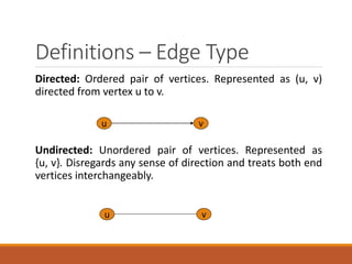
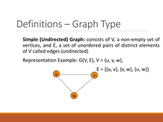
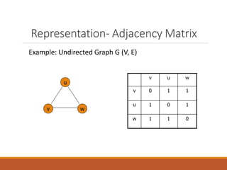
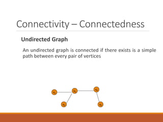
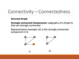
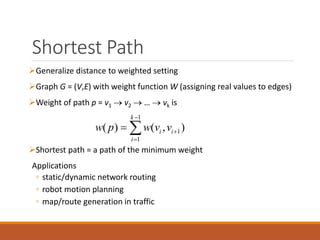
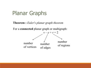
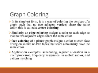
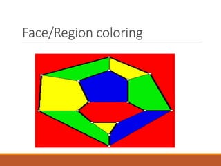
Graph Theory
Varying Applications (examples)
Computer networks
Distinguish between two chemical compounds
with the same molecular formula but different
structures
Solve shortest path problems between cities
Topics Covered
Definitions
Types
Terminology
Representation
Connectivity
Shortest Path
Planar Graphs
Graph Coloring
Definitions - Graph
A graph is any collection of
• Dots (Vertices)
• Arcs/Lines (Edges) that join the points
Representation: Graph G =(V, E) consists set of vertices denoted
by V, or by V(G) and set of edges E, or E(G)
Definitions – Edge Type
Directed: Ordered pair of vertices. Represented as (u, v)
directed from vertex u to v.
Undirected: Unordered pair of vertices. Represented as
{u, v}. Disregards any sense of direction and treats both end
vertices interchangeably.
u v
u v
Definitions – Edge Type
Loop: A loop is an edge whose endpoints are equal i.e., an
edge joining a vertex to it self is called a loop. Represented
as {u, u} = {u}
Multiple Edges: Two or more edges joining the same pair of
vertices.
u
Definitions – Graph Type
Simple (Undirected) Graph: consists of V, a non-empty set of
vertices, and E, a set of unordered pairs of distinct elements
of V called edges (undirected)
Representation Example: G(V, E), V = {u, v, w},
E = {{u, v}, {v, w}, {u, w}}
u v
w
Graph theory
Example: Draw graph with
(a) 4 vertices and 5 edges
(b) 4 vertices and 3 edges (no loops)
(c) 3 vertices and 4 edges
Definitions – Graph Type
Multigraph: G(V,E), consists of set of vertices V, set of
Edges E and a function f from E to {{u, v}| u, v V, u ≠ v}. The
edges e1 and e2 are called multiple or parallel edges if
f (e1) = f (e2).
Representation Example: V = {u, v, w}, E = {e1, e2, e3}
u
v
w
e1
e2
e3
Definitions – Graph Type
Directed Graph: G(V, E), set of vertices V, and set of Edges E,
that are ordered pair of elements of V (directed edges)
Representation Example: G(V, E), V = {u, v, w}, E = {(u, v), (v,
w), (w, u)}
u
w
v
Definitions – Graph Type
Directed Multigraph: G(V,E), consists of set of vertices V, set
of Edges E and a function f from E to {{u, v}| u, v V}. The
edges e1 and e2 are multiple edges if f(e1) = f(e2)
Representation Example: V = {u, v, w}, E = {e1, e2, e3, e4}
u
w
v
e1
e2
e3
e4
Simple graphs – special cases
Complete graph: Kn, is the simple graph that contains exactly
one edge between each pair of distinct vertices.
Representation Example: K1, K2, K3, K4
K2
K1
K4
K3
Representation
Incidence (Matrix): Most useful when information about
edges is more desirable than information about vertices.
Adjacency (Matrix/List): Most useful when information about
the vertices is more desirable than information about the
edges. These two representations are also most popular since
information about the vertices is often more desirable than
edges in most applications
Representation- Incidence Matrix
Representation Example: G = (V, E)
e1 e2 e3
v 1 0 1
u 1 1 0
w 0 1 1
v w
u
e1
e3
e2
Representation- Adjacency Matrix
Example: Undirected Graph G (V, E)
v u w
v 0 1 1
u 1 0 1
w 1 1 0
u
v w
Representation- Adjacency Matrix
Example: directed Graph G (V, E)
v u w
v 0 1 0
u 0 0 1
w 1 0 0
u
v w
Representation- Adjacency List
Each node (vertex) has a list of which nodes (vertex) it is adjacent
Example: undirectd graph G (V, E)
node Adjacency List
u v , w
v w, u
w u , v
u
v w
Connectivity
Basic Idea: In a Graph Reachability among vertices by traversing
the edges
Application Example:
- In a city to city road-network, if one city can be reached from
another city.
- Problems if determining whether a message can be sent
between two computers using intermediate links
- Efficiently planning routes for data delivery in the Internet
Connectivity – Path
A Path is a sequence of edges that begins at a vertex of a
graph and travels along edges of the graph, always connecting
pairs of adjacent vertices.
Representation example: G = (V, E), Path P represented, from u
to v is {{u, 1}, {1, 4}, {4, 5}, {5, v}}
1
u
3
4 5
2
v
Connectivity – Connectedness
Undirected Graph
An undirected graph is connected if there exists is a simple
path between every pair of vertices
v1
v2
v3
v5
v4
Connectivity – Connectedness
Directed Graph
Representation example: G1 (Strong component), G2 (Weak
Component), G3 is undirected graph representation of G2 or
G1
G2
G1 G3
Connectivity – Connectedness
Directed Graph
Strongly connected Components: subgraphs of a Graph G
that are strongly connected
Representation example: G1 is the strongly connected
component in G
G1
G
Representation- Incidence Matrix
e1 e2 e3
a 1 0 0
b 1 1 0
c 0 1 1
d 0 0 1
e 0 0 0
f 0 0 0
e4 e5 e6 e7
0 0 0 1
0 0 0 0
0 1 1 0
1 0 0 0
1 1 0 0
0 0 1 1
a b
c d
e
f
e1
e2
e3
e4
e5
e6
e7
Shortest Path
Generalize distance to weighted setting
Graph G = (V,E) with weight function W (assigning real values to edges)
Weight of path p = v1  v2  …  vk is
Shortest path = a path of the minimum weight
Applications
◦ static/dynamic network routing
◦ robot motion planning
◦ map/route generation in traffic
1
1
1
( ) ( , )
k
i i
i
w p w v v



 
Planar Graphs
Planar graph is a graph that can be embedded in the plane, i.e.,
it can be drawn on the plane in such a way that its edges intersect
only at their endpoints.
In other words, it can be drawn in such a way that no edges
cross each other.
Planar Graphs
Representation examples: Q3
Planar Graphs
Theorem : Euler's planar graph theorem
For a connected planar graph or multigraph:
v – e + r = 2
number
of vertices
number
of edges
number
of regions
Planar Graphs
Planar Graphs
Example of Euler’s theorem
K4
R1
R2
R3
A planar graph divides the plane
into several regions (faces)
v=4,e=6,r=4, v-e+r=2
R4
Graph Coloring
 In its simplest form, it is a way of coloring the vertices of a
graph such that no two adjacent vertices share the same
color; this is called a vertex coloring.
Similarly, an edge coloring assigns a color to each edge so
that no two adjacent edges share the same color
face coloring of a planar graph assigns a color to each face
or region so that no two faces that share a boundary have the
same color.
Application examples: scheduling, register allocation in a
microprocessor, frequency assignment in mobile radios, and
pattern matching
Vertex Coloring
Edge coloring
Face/Region coloring

Tn 110 lecture 8

  • 1.
  • 2.
    Varying Applications (examples) Computernetworks Distinguish between two chemical compounds with the same molecular formula but different structures Solve shortest path problems between cities
  • 3.
  • 4.
    Definitions - Graph Agraph is any collection of • Dots (Vertices) • Arcs/Lines (Edges) that join the points Representation: Graph G =(V, E) consists set of vertices denoted by V, or by V(G) and set of edges E, or E(G)
  • 5.
    Definitions – EdgeType Directed: Ordered pair of vertices. Represented as (u, v) directed from vertex u to v. Undirected: Unordered pair of vertices. Represented as {u, v}. Disregards any sense of direction and treats both end vertices interchangeably. u v u v
  • 6.
    Definitions – EdgeType Loop: A loop is an edge whose endpoints are equal i.e., an edge joining a vertex to it self is called a loop. Represented as {u, u} = {u} Multiple Edges: Two or more edges joining the same pair of vertices. u
  • 7.
    Definitions – GraphType Simple (Undirected) Graph: consists of V, a non-empty set of vertices, and E, a set of unordered pairs of distinct elements of V called edges (undirected) Representation Example: G(V, E), V = {u, v, w}, E = {{u, v}, {v, w}, {u, w}} u v w
  • 8.
    Graph theory Example: Drawgraph with (a) 4 vertices and 5 edges (b) 4 vertices and 3 edges (no loops) (c) 3 vertices and 4 edges
  • 9.
    Definitions – GraphType Multigraph: G(V,E), consists of set of vertices V, set of Edges E and a function f from E to {{u, v}| u, v V, u ≠ v}. The edges e1 and e2 are called multiple or parallel edges if f (e1) = f (e2). Representation Example: V = {u, v, w}, E = {e1, e2, e3} u v w e1 e2 e3
  • 10.
    Definitions – GraphType Directed Graph: G(V, E), set of vertices V, and set of Edges E, that are ordered pair of elements of V (directed edges) Representation Example: G(V, E), V = {u, v, w}, E = {(u, v), (v, w), (w, u)} u w v
  • 11.
    Definitions – GraphType Directed Multigraph: G(V,E), consists of set of vertices V, set of Edges E and a function f from E to {{u, v}| u, v V}. The edges e1 and e2 are multiple edges if f(e1) = f(e2) Representation Example: V = {u, v, w}, E = {e1, e2, e3, e4} u w v e1 e2 e3 e4
  • 12.
    Simple graphs –special cases Complete graph: Kn, is the simple graph that contains exactly one edge between each pair of distinct vertices. Representation Example: K1, K2, K3, K4 K2 K1 K4 K3
  • 13.
    Representation Incidence (Matrix): Mostuseful when information about edges is more desirable than information about vertices. Adjacency (Matrix/List): Most useful when information about the vertices is more desirable than information about the edges. These two representations are also most popular since information about the vertices is often more desirable than edges in most applications
  • 14.
    Representation- Incidence Matrix RepresentationExample: G = (V, E) e1 e2 e3 v 1 0 1 u 1 1 0 w 0 1 1 v w u e1 e3 e2
  • 15.
    Representation- Adjacency Matrix Example:Undirected Graph G (V, E) v u w v 0 1 1 u 1 0 1 w 1 1 0 u v w
  • 16.
    Representation- Adjacency Matrix Example:directed Graph G (V, E) v u w v 0 1 0 u 0 0 1 w 1 0 0 u v w
  • 17.
    Representation- Adjacency List Eachnode (vertex) has a list of which nodes (vertex) it is adjacent Example: undirectd graph G (V, E) node Adjacency List u v , w v w, u w u , v u v w
  • 18.
    Connectivity Basic Idea: Ina Graph Reachability among vertices by traversing the edges Application Example: - In a city to city road-network, if one city can be reached from another city. - Problems if determining whether a message can be sent between two computers using intermediate links - Efficiently planning routes for data delivery in the Internet
  • 19.
    Connectivity – Path APath is a sequence of edges that begins at a vertex of a graph and travels along edges of the graph, always connecting pairs of adjacent vertices. Representation example: G = (V, E), Path P represented, from u to v is {{u, 1}, {1, 4}, {4, 5}, {5, v}} 1 u 3 4 5 2 v
  • 20.
    Connectivity – Connectedness UndirectedGraph An undirected graph is connected if there exists is a simple path between every pair of vertices v1 v2 v3 v5 v4
  • 21.
    Connectivity – Connectedness DirectedGraph Representation example: G1 (Strong component), G2 (Weak Component), G3 is undirected graph representation of G2 or G1 G2 G1 G3
  • 22.
    Connectivity – Connectedness DirectedGraph Strongly connected Components: subgraphs of a Graph G that are strongly connected Representation example: G1 is the strongly connected component in G G1 G
  • 23.
    Representation- Incidence Matrix e1e2 e3 a 1 0 0 b 1 1 0 c 0 1 1 d 0 0 1 e 0 0 0 f 0 0 0 e4 e5 e6 e7 0 0 0 1 0 0 0 0 0 1 1 0 1 0 0 0 1 1 0 0 0 0 1 1 a b c d e f e1 e2 e3 e4 e5 e6 e7
  • 24.
    Shortest Path Generalize distanceto weighted setting Graph G = (V,E) with weight function W (assigning real values to edges) Weight of path p = v1  v2  …  vk is Shortest path = a path of the minimum weight Applications ◦ static/dynamic network routing ◦ robot motion planning ◦ map/route generation in traffic 1 1 1 ( ) ( , ) k i i i w p w v v     
  • 25.
    Planar Graphs Planar graphis a graph that can be embedded in the plane, i.e., it can be drawn on the plane in such a way that its edges intersect only at their endpoints. In other words, it can be drawn in such a way that no edges cross each other.
  • 26.
  • 27.
  • 28.
    Theorem : Euler'splanar graph theorem For a connected planar graph or multigraph: v – e + r = 2 number of vertices number of edges number of regions Planar Graphs
  • 29.
    Planar Graphs Example ofEuler’s theorem K4 R1 R2 R3 A planar graph divides the plane into several regions (faces) v=4,e=6,r=4, v-e+r=2 R4
  • 30.
    Graph Coloring  Inits simplest form, it is a way of coloring the vertices of a graph such that no two adjacent vertices share the same color; this is called a vertex coloring. Similarly, an edge coloring assigns a color to each edge so that no two adjacent edges share the same color face coloring of a planar graph assigns a color to each face or region so that no two faces that share a boundary have the same color. Application examples: scheduling, register allocation in a microprocessor, frequency assignment in mobile radios, and pattern matching
  • 31.
  • 32.
  • 33.