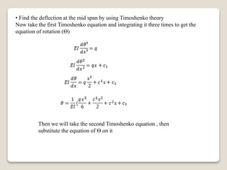
Gaziantep university
Structure mechanic
Comparison of Bernoulli-EULER and
Timoshenko Beam
Presented by
Mohammed Muneam Mohammed
Student number: 201623647
Content
- Introduction to Classical “Euler- Bernoulli” Theory
- Timoshenko Beam Theory
- Finite Element of Timoshenko Beam and Euler- Bernoulli”
Theory
- References
Introduction to Classical “Euler- Bernoulli” Theory
• This is a well-Known the classical theory of Euler-Bernoulli beam assumes that:
• The cross- section plane perpendicular to the axis of the beam remains plane after
deformation “assumption of a rigid cross-section plane .
• The deformed cross-section plane is still perpendicular to the axis after deformation.
• The classical theory of the beam neglects transverse shearing deformation where the
transverse shear stress is determined by the equation of equilibrium. This is applicable
to a thin beam.
Euler- Bernoulli beam element
The strain in (x) direction
And the stress :
And the resultant bending moment on the cross section area
For a beam with short effective length (length/depth < 5),( or composite
beams , plates and shells , it is inapplicable to neglect the transverse shear
deformation. In 1921 , Timoshenko presented a revised beam theory
considering shear deformation which retains the first assumption and satisfies
the stress-strain relations of shear. The difference between the Timoshenko
beam and the technical, Bernoulli, beam is that the former includes the effect
of the shear stresses on the deformation. A constant shear over the beam
height is assumed..
Timoshenko beam element
Timoshenko Beam Theory
Let the X axis be along the beam axis before deformation and the XZ plane be
the deflection plane as shown in fig. above . The bending problem of a
Timoshenko beam is considered the displacements û(x, z), ŵ(x, z) at any point
(x , z) in the beam along X-axis and Z-axis ,respectively ,can be expressed in
terms of two generalized displacements ,i.e. the deflection of beam axis w̃(x)
and the rotation angle of the cross section Ѳ˜(x).
û(x, z) = −z θ̃(x), ŵ(x, z) = w̃(x)
Bending of Timoshenko beam
According to strain displacement
єᵪ =
=
Since Ѳ(x) is a function of (x) only, then the partial differential symbol can be replaced
by an ordinary differential symbol
substituting equations above in stress – strain relationship get
……….(1)
………(2)
Multiplying both sides of equation (1) by (z) and integrating over the cross-
section area .
……..(3)
And further , integrating both sides of equation (2) directly over the cross-section
area, we obtain:
……..(4)
When deducing the above equations , we assume constant shear stress on the cross
section, which however are not true in actual situation. Hence a shear correction factor
(K) of the cross section always introduced in equation (4) . Equation (3) and (4)
becomes :
M= EI K
Fs= K GAϓ
Where
K=
And ϓ=
Physically , they are referred as the relative rotation angle between two adjacent cross
sections and the shear angle of section respectively . To determine the shear correction
factor (K) it is usually to assume beforehand the type of shear stress distribution on
various shape of cross sections. Different assumption results in different numerical values.
For example K=1→1.2 for rectangular cross sections . An infinite shear correction factor
K→ infinity , implies negligible effect of transverse shear deformation and the model
degenerates to the classical theory of Euler- Bernoulli Beam
The equilibrium equations of the Timoshenko beam theory are the same as those of the
Euler – Bernoulli beam theory.
For Timoshenko beam
And the strain
The equation of equilibrium:
And we know that:
Then, substitute the last two equations in the equilibrium equation get:
These last two equations are called the Timoshenko beam equations
Finite Element of Timoshenko Beam
In Euler-Bernoulli beam there are four degrees of freedom ( w₁ , w₂, Ѳ₁ ,Ѳ₂ )
then the stiffness matrix is (4*4).which has the form :
And the displacement w(x)=N₁(x) Z₁+ N₂(x)Ѳ₁+N₃(x)Z₂+N₄(x)Ѳ₂……..(*)
The potential energy has a bending strain component and a shear
strain component.
Then there are two types of bending: the first because of the moment and
the second because of the shear, therefore; two equations for deflection
shape will be assumed:
Then, substituting it in the equation of potential energy we will get the
shape function:
The transverse deformation of a beam with shear and bending strains may
be separated into a portion related to shear deformation and a portion
related to bending deformation
It can be shown that the following shape functions satisfy the Timoshenko
beam equations
The same steps used to derivative the stiffness of Bernoulli-
Euler beam will be used to find the stiffness matrix for
Timoshenko beam.
To explain effect of the shear stress i.e. the difference between Euler-Bernoulli
and Timoshenko theories. we will take a simply supported beam and find the
deflection at the mid span by using Timoshenko theory and Euler-Bernoulli
theory . In each method we will find the deflection by Exact solution once and
by numerical method (Finite Element Analysis) . And make a comparison
between the results.
We have a simply supported beam as shown below, subjected to distributed load
(q) at all its length (L)
L
We will began with the Exact solution:
q
• Find the deflection at the mid span by using Timoshenko theory
Now take the first Timoshenko equation and integrating it three times to get the
equation of rotation (Ѳ)
Then we will take the second Timoshenko equation , then
substitute the equation of Ѳ on it
Use the boundary conditions:
At x=0, w(x) = 0
At x=0, = 0
At x=L, w(x) = 0
At x=L, = 0
Applying the above boundary conditions get
c₂=0 , , c₄= 0
At x=L/2:
Now will find the deflection at the mid span by using Euler-Bernoulli theory:
Integrating this equation two times with respect to x and applying the boundary
conditions:
At x = 0 , w = 0
At x = L , w = 0
We will get:
At x = L/2 :
If we return to Timoshenko displacement
Then the magnitude represented the effect of shear
stress
-Now we will find the displacement at the mid span by using the finite
element analysis.
• For Euler-Bernoulli beam.
Step 1- divide the beam in to two equal element
Step 2- find the stiffness matrix of each element
The stiffness matrix is the same for two elements
Make assembly for the two stiffness matrices to find the global stiffness matrix
Step 3- find the displacement vector
Step 4 - find the force vector.
=
Apply the equation F= K d, and find the displacement in the node 2. and
knowing that u₁= 0 ,u₃= 0 and Ѳ₂= 0, then find u₂
Now use Timoshenko theory, we will make the same steps that used in Euler-
Bernoulli beam, but the stiffness matrix will differ
Where
The two elements have the same stiffness matrix.
Now we will made assembly, to get the global stiffness matrix
Specify the displacement vector :
And the force vector
And knowing that u₁= 0 , u₃= 0 and Ѳ₂= 0 , applying the equation :
F= K d
We will find that:
When we compare this result with the exact solution result
We find there is small difference , that difference may be reduced if we used more
elements.
The value inside the bracket represent the effect of traverse shear strain
References
1- Bathe, K.J., Finite Element Procedures, Prentice Hall,
1996
2- Schäfer, M., Numerik im Maschinenbau, Springer,
1999
3- Henri P. Gavin , Spring, STRUCTURAL ELEMENT
STIFFNESS MATRICES AND MASS MATRICES,2010
4- SYMPLECTIC ELASTICITY
© World Scientific Publishing Co. Pte. Ltd.
http://www.worldscibooks.com/engineering/6656.html
5- Dr Fehmi Cirak, Finite Element Formulation for Beams
6-Jose Palacios, Finite Element Method Beams, July 2008
7-Timoshenko beam theory , Wikipedia, the free encyclopedia
36

Timoshenko beam-element

  • 1.
    Gaziantep university Structure mechanic Comparisonof Bernoulli-EULER and Timoshenko Beam Presented by Mohammed Muneam Mohammed Student number: 201623647
  • 2.
    Content - Introduction toClassical “Euler- Bernoulli” Theory - Timoshenko Beam Theory - Finite Element of Timoshenko Beam and Euler- Bernoulli” Theory - References
  • 3.
    Introduction to Classical“Euler- Bernoulli” Theory • This is a well-Known the classical theory of Euler-Bernoulli beam assumes that: • The cross- section plane perpendicular to the axis of the beam remains plane after deformation “assumption of a rigid cross-section plane . • The deformed cross-section plane is still perpendicular to the axis after deformation. • The classical theory of the beam neglects transverse shearing deformation where the transverse shear stress is determined by the equation of equilibrium. This is applicable to a thin beam.
  • 4.
    Euler- Bernoulli beamelement The strain in (x) direction And the stress :
  • 5.
    And the resultantbending moment on the cross section area
  • 6.
    For a beamwith short effective length (length/depth < 5),( or composite beams , plates and shells , it is inapplicable to neglect the transverse shear deformation. In 1921 , Timoshenko presented a revised beam theory considering shear deformation which retains the first assumption and satisfies the stress-strain relations of shear. The difference between the Timoshenko beam and the technical, Bernoulli, beam is that the former includes the effect of the shear stresses on the deformation. A constant shear over the beam height is assumed.. Timoshenko beam element
  • 7.
    Timoshenko Beam Theory Letthe X axis be along the beam axis before deformation and the XZ plane be the deflection plane as shown in fig. above . The bending problem of a Timoshenko beam is considered the displacements û(x, z), ŵ(x, z) at any point (x , z) in the beam along X-axis and Z-axis ,respectively ,can be expressed in terms of two generalized displacements ,i.e. the deflection of beam axis w̃(x) and the rotation angle of the cross section Ѳ˜(x). û(x, z) = −z θ̃(x), ŵ(x, z) = w̃(x) Bending of Timoshenko beam
  • 8.
    According to straindisplacement єᵪ = = Since Ѳ(x) is a function of (x) only, then the partial differential symbol can be replaced by an ordinary differential symbol substituting equations above in stress – strain relationship get
  • 9.
    ……….(1) ………(2) Multiplying both sidesof equation (1) by (z) and integrating over the cross- section area . ……..(3) And further , integrating both sides of equation (2) directly over the cross-section area, we obtain:
  • 10.
    ……..(4) When deducing theabove equations , we assume constant shear stress on the cross section, which however are not true in actual situation. Hence a shear correction factor (K) of the cross section always introduced in equation (4) . Equation (3) and (4) becomes : M= EI K Fs= K GAϓ Where K=
  • 11.
    And ϓ= Physically ,they are referred as the relative rotation angle between two adjacent cross sections and the shear angle of section respectively . To determine the shear correction factor (K) it is usually to assume beforehand the type of shear stress distribution on various shape of cross sections. Different assumption results in different numerical values. For example K=1→1.2 for rectangular cross sections . An infinite shear correction factor K→ infinity , implies negligible effect of transverse shear deformation and the model degenerates to the classical theory of Euler- Bernoulli Beam The equilibrium equations of the Timoshenko beam theory are the same as those of the Euler – Bernoulli beam theory.
  • 12.
  • 13.
    The equation ofequilibrium: And we know that: Then, substitute the last two equations in the equilibrium equation get: These last two equations are called the Timoshenko beam equations
  • 14.
    Finite Element ofTimoshenko Beam In Euler-Bernoulli beam there are four degrees of freedom ( w₁ , w₂, Ѳ₁ ,Ѳ₂ ) then the stiffness matrix is (4*4).which has the form : And the displacement w(x)=N₁(x) Z₁+ N₂(x)Ѳ₁+N₃(x)Z₂+N₄(x)Ѳ₂……..(*)
  • 15.
    The potential energyhas a bending strain component and a shear strain component.
  • 17.
    Then there aretwo types of bending: the first because of the moment and the second because of the shear, therefore; two equations for deflection shape will be assumed: Then, substituting it in the equation of potential energy we will get the shape function:
  • 19.
    The transverse deformationof a beam with shear and bending strains may be separated into a portion related to shear deformation and a portion related to bending deformation It can be shown that the following shape functions satisfy the Timoshenko beam equations
  • 20.
    The same stepsused to derivative the stiffness of Bernoulli- Euler beam will be used to find the stiffness matrix for Timoshenko beam.
  • 21.
    To explain effectof the shear stress i.e. the difference between Euler-Bernoulli and Timoshenko theories. we will take a simply supported beam and find the deflection at the mid span by using Timoshenko theory and Euler-Bernoulli theory . In each method we will find the deflection by Exact solution once and by numerical method (Finite Element Analysis) . And make a comparison between the results. We have a simply supported beam as shown below, subjected to distributed load (q) at all its length (L) L We will began with the Exact solution: q
  • 22.
    • Find thedeflection at the mid span by using Timoshenko theory Now take the first Timoshenko equation and integrating it three times to get the equation of rotation (Ѳ) Then we will take the second Timoshenko equation , then substitute the equation of Ѳ on it
  • 23.
    Use the boundaryconditions: At x=0, w(x) = 0 At x=0, = 0 At x=L, w(x) = 0 At x=L, = 0
  • 24.
    Applying the aboveboundary conditions get c₂=0 , , c₄= 0 At x=L/2: Now will find the deflection at the mid span by using Euler-Bernoulli theory:
  • 25.
    Integrating this equationtwo times with respect to x and applying the boundary conditions: At x = 0 , w = 0 At x = L , w = 0 We will get: At x = L/2 : If we return to Timoshenko displacement
  • 26.
    Then the magnituderepresented the effect of shear stress -Now we will find the displacement at the mid span by using the finite element analysis. • For Euler-Bernoulli beam. Step 1- divide the beam in to two equal element Step 2- find the stiffness matrix of each element The stiffness matrix is the same for two elements
  • 27.
    Make assembly forthe two stiffness matrices to find the global stiffness matrix Step 3- find the displacement vector
  • 28.
    Step 4 -find the force vector.
  • 29.
    = Apply the equationF= K d, and find the displacement in the node 2. and knowing that u₁= 0 ,u₃= 0 and Ѳ₂= 0, then find u₂
  • 30.
    Now use Timoshenkotheory, we will make the same steps that used in Euler- Bernoulli beam, but the stiffness matrix will differ
  • 31.
    Where The two elementshave the same stiffness matrix. Now we will made assembly, to get the global stiffness matrix
  • 32.
  • 33.
    And the forcevector And knowing that u₁= 0 , u₃= 0 and Ѳ₂= 0 , applying the equation : F= K d We will find that:
  • 34.
    When we comparethis result with the exact solution result We find there is small difference , that difference may be reduced if we used more elements. The value inside the bracket represent the effect of traverse shear strain
  • 35.
    References 1- Bathe, K.J.,Finite Element Procedures, Prentice Hall, 1996 2- Schäfer, M., Numerik im Maschinenbau, Springer, 1999 3- Henri P. Gavin , Spring, STRUCTURAL ELEMENT STIFFNESS MATRICES AND MASS MATRICES,2010 4- SYMPLECTIC ELASTICITY © World Scientific Publishing Co. Pte. Ltd. http://www.worldscibooks.com/engineering/6656.html 5- Dr Fehmi Cirak, Finite Element Formulation for Beams 6-Jose Palacios, Finite Element Method Beams, July 2008 7-Timoshenko beam theory , Wikipedia, the free encyclopedia
  • 36.