Download as PDF, PPTX

![8
ρ = Mass per unit height, H= total height, y= Any distance along
height and k = lateral stiffness of cantilever member = EI/H3
0.227 ρ .H
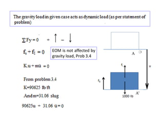
Equivalent lumped mass model is
determined using a shape function (?),
Ψ(y) = [1-Cos (πy/2H)].
Equivalent lumped mass SDOF system of a cantilever
wall with uniform x-sectional area
H
Ψ(y)](https://image.slidesharecdn.com/module3updated4-220516145835-23e31340/85/Module-3_-Spring-2020-pdf-8-320.jpg)
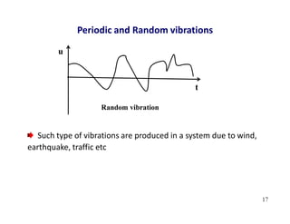
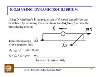
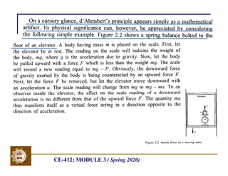
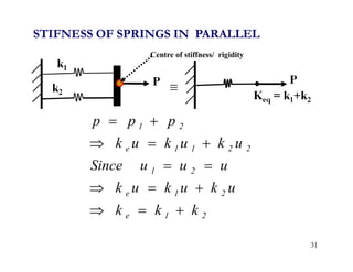
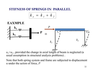
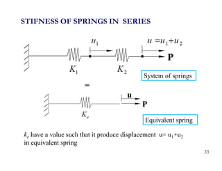
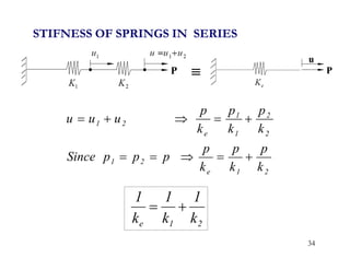
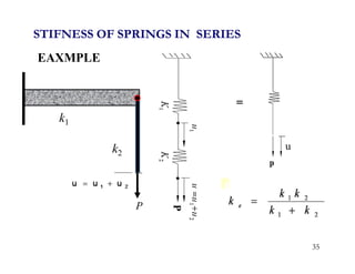
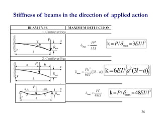
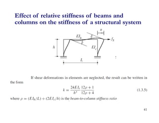
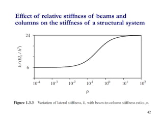
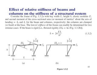
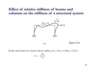
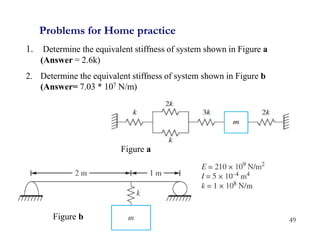
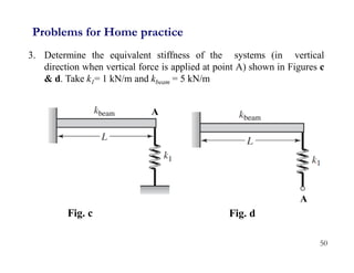

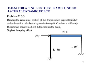
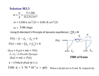

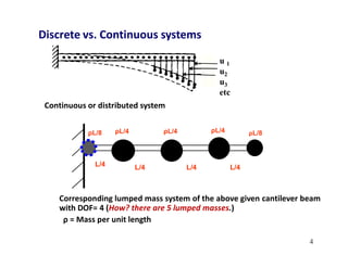
1. The document discusses fundamentals of dynamic analysis for single degree of freedom (SDOF) systems, including structural degrees of freedom, discrete vs continuous systems, idealization of structures as SDOF systems, and formulation of equations of motion. 2. Key concepts covered include lumped mass vs distributed mass systems, modeling of beams and frames as SDOF systems, derivation of equations of motion using Newton's laws and D'Alembert's principle, and modeling of damping. 3. Examples are provided for determining equivalent stiffness of springs in series and parallel, and calculating stiffness of typical structural elements like beams and frames. Problems are given at the end for practice.


![Geotechnical Engineering-I [Lec #24: Soil Permeability - II]](https://cdn.slidesharecdn.com/ss_thumbnails/24-180924141149-thumbnail.jpg?width=640&height=640&fit=bounds)


![Module 14 [Compatibility Mode].pdf](https://cdn.slidesharecdn.com/ss_thumbnails/module14compatibilitymode-221005020212-a4e2d1ee-thumbnail.jpg?width=640&height=640&fit=bounds)