This paper introduces a Third Harmonic Blocking Transformer (THBT) designed to suppress third harmonic currents in three-phase systems, particularly those with unbalanced single-phase loads. It compares the THBT with traditional Zero Sequence Blocking Transformers (ZSBT) and discusses its construction, working principles, design considerations, and simulation results demonstrating its superiority in reducing harmonic distortion while maintaining low impedance for fundamental frequencies. The THBT is presented as a reliable, cost-effective solution for improving power quality in industrial and power distribution applications.
![Indonesian Journal of Electrical Engineering and Computer Science
Vol. 25, No. 2, February 2022, pp. 697~709
ISSN: 2502-4752, DOI: 10.11591/ijeecs.v25.i2.pp697-709 697
Journal homepage: http://ijeecs.iaescore.com
Third harmonic current minimization using third harmonic
blocking transformer
Vishnuprasada Vittal Bhat, Pinto Pius
Department of Electronics and Electrical Engineering, NMAMIT, Nitte, India
Article Info ABSTRACT
Article history:
Received Sep 1, 2021
Revised Dec 22, 2021
Accepted Dec 29, 2021
Zero sequence blocking transformers (ZSBTs) are used to suppress third
harmonic currents in 3-phase systems. Three-phase systems where single-
phase loading is present, there is every chance that the load is not balanced.
If there is zero-sequence current due to unequal load current, then the ZSBT
will impose high impedance and the supply voltage at the load end will be
varied which is not desired. This paper presents Third harmonic blocking
transformer (THBT) which suppresses only higher harmonic zero sequences.
The constructional features using all windings in single-core and
construction using three single-phase transformers explained. The paper
discusses the constructional features, full details of circuit usage, design
considerations, and simulation results for different supply and load
conditions. A comparison of THBT with ZSBT is made with simulation
results by considering four different cases.
Keywords:
Industrial power systems
Power distribution lines
Power harmonic filters
Power quality
Power system harmonics
This is an open access article under the CC BY-SA license.
Corresponding Author:
Vishnuprasada Vittal Bhat
Department of Electronics and Electrical Engineering, NMAMIT
Nitte, India
Email: vishnupangala@gmail.com
1. INTRODUCTION
Power quality is very important in a power system. The removal of the third harmonic is very
difficult as it is near to fundamental. There are different technologies to remove third harmonics. The below
discussion reveals problems with different technologies:
a) Using an inductor in series with the line can be implemented for individual loads. If implemented for
industrial loads where both single-phase and three-phase loads are present, due to unequal single-phase
loads or unbalanced loads, the voltage drop in phase will be unequal and hence supply voltage also
varies that causing further unbalance which is not desirable. As the entire phase current flows through
the inductance, the copper loss is also more.
b) If ZSBT [1]-[4] is used, power loss is less. But if an unbalanced current (zero-sequence current) flows
due to single-phase loading, the voltage drop in lines will be different, and hence even if the three-phase
balanced load is present, it causes increased unbalanced current.
c) A star-delta transformer [5] or a zigzag transformer [6] can be connected in parallel with a load but if a
very small zero sequence component is present in supply voltage, then it will draw a very high current
which causes more losses.
d) Active filters/active line conditioners [7] are the better option but are more complex and the cost is also
higher compared to passive filters. Also, they are not reliable as compared to passive filters.
Differential protection is the most effective protection against internal defects for power
transformers. The protection uses differential currents, which differ from the primary currents to the second
one [8], [9]. The differential relay is utilized to protect the transformer, alternator, and HT motor. If the](https://image.slidesharecdn.com/26089-51875-1-pb-240517090214-45697db7/75/Third-harmonic-current-minimization-using-third-harmonic-blocking-transformer-1-2048.jpg)
![ ISSN: 2502-4752
Indonesian J Elec Eng & Comp Sci, Vol. 25, No. 2, February 2022: 697-709
698
transformer winding faults, the relay will trip. The differential relay must remain inoperative when the
problem is outside of the area. The differential relay should detect energy inrush and prohibit operation. The
relay must also be temporarily removed from operation to allow the transformer to be placed in service. This
is not an option in the majority of cases. The harmonics are usually small in faults. The second harmonic, on
the other hand, is a key part of the inrush current. The second harmonic thus offers an efficient technique of
differentiating between faults and inrush [10], [11]. Inrush currents are produced by transients in the
magnetic transformers before the flux is stable [12]. The following include early efforts to prevent
differential relay operations resulting from inrush:
Introduce a delay in the differential relay intentionally [13].
The relay has been desensitized for a period to override inrush.
To restrict or govern the differential relay, add a voltage signal.
When a transformer is energized, transient current may appear up to 10 to 15 times more than the
rated transformer current. These inrush currents can continue for a few seconds for big transformers until the
transient is lost. Transformer inrush is a high current, affecting the surrounded device's lifetime on the
network and creating protection selection and stability difficulties. This phenomenon must therefore be
included in the calculation of relay settings [14]. Hence, we need a system that should be very simple, it
should have fewer/no active components and ideally, it should have high impedance for only harmonic
current and no effect on fundamental currents.
Jiang et al. [15] have designed a harmonic blocking system to send the GOOSE-based harmonic
blocking signal to the backup current relay (SEL751A) via the element (87HB) of the transformer differential
relay to prevent from tripping during the transformer magnetizing inrush current conditions. The results of
the simulation demonstrate that the default protection system IEC61850 is faster than the hardwired signals.
The transformer system hence improves speed and reliability using the standard GOOSE application
IEC61850.
Shaikh et al. [16] proposed a zigzag transformer to minimize the harmonic currents and the neutral
overload. The various nature of the loads connected to the four-phase three-wire distribution system. These
may include personal computers, automatic machines, variable speed drives, lighting ballasts, and other
electronic power systems, which can cause zero sequence current in the system to fluctuate in the neutral
supply system. This could lead to major problems of power quality and reduction. One method for reducing
the neutral current and for reducing the harmonic zero sequence currents of distributive systems is a zigzag
transformer. Rahman et al. [17] examined the variation of THD for the THPWM technology by modifying
the carriers' frequency and index of modulation. The research suggests an optimal condition that provides the
lowest THD for that ideal state. A modified THPWM approach is suggested in this research. This proposed
method of modulation helps to minimize the THD to the lowest value than the approach THPWM.
Eltamaly [18] introduced a new current injection system for harmonically reducing renewable
energy utility interface three-phase controlled converters. In renewable energy applications such as
photovoltaics and wind energy, three-phase controlled or uncontrolled converters have been applied as
rectifiers and inverters. The fundamental disadvantage of these converters is that their line currents are high
THD. This difficulty was remedied by many approaches. One of the greatest options for a harmonic
reduction of these converters' line currents is a third harmonic current injection. The injection into the line
currents of the third harmonic current from dc-bus decreases its harmonic contents.
Almutairi and Hadjiloucas [19] has been proposed a new method for the suppression of distortions,
for non-sinusoidal power systems to use the non-linearity current index (NLCI) to define the shunt single-
tune passive filter (STPF). The aim was to maintain a power factor within the required range. The purpose of
the approach is to minimize the nonlinear current of customer's loads at the point of common coupling in the
power system (PCC). Gbadamosi et al. [20] focuses on finding an optimum model of power flow
optimization to minimize power loss and RES harmonics with a concentration on minimizing their effects on
local marginal prices. The electrical transient analyzer program 12.6.0 has been used to evaluate the
magnitude of harmonics, grid modeling, and simulation using RES, such as wind and solar energy.
Arafat and Choi [21] introduced a five-stage permanent magnet assisted synchronous reticence
motor (PMa-SynRM) for the smart and adaptive performance of torque ripple minimization (TRM) in open-
stage faults. Due to its potential fault tolerance and wide-speed operation capabilities, the five-phase machine
is gaining more attention. Furthermore, the torque ripple is significantly enhanced by harmful vibrations
during fault tolerance. Yet, the majority of TRM has been undertaken simply to preserve continuous MMF
while evaluating its fundamental harmonic. But even huge torque variations are induced by suddenly
modulated harmonic oscillations of a high order which are uncertain.
Routray et al. [22] proposed a modified particle swarm optimization (MPSO) in the three-phase
eleven-level hybrid cascaded multilevel inverter (HC-MLI) for rapid convergence and harmonic
minimization. In the proposed work on the synthesis of an eleven-level output voltage employing two dc](https://image.slidesharecdn.com/26089-51875-1-pb-240517090214-45697db7/75/Third-harmonic-current-minimization-using-third-harmonic-blocking-transformer-2-2048.jpg)
![Indonesian J Elec Eng & Comp Sci ISSN: 2502-4752
Third harmonic current minimization using third harmonic blocking … (Vishnuprasada Vittal Bhat)
699
sources, a pre-charged capacitor, and twelve switches, Selective harmonic elimination pulse width
modulation (SHE-PWM) was performed. To remove the lower-order odd harmonics like 5th, 7th, 11th, and
13th from the HCMLI output voltage, the three-phase eleven-level HC-MLI switching angles were
determined.
Yadav et al. [23] studied the transformerless function of the MMC. The MMC's internal dynamic
produces a third-order voltage ripple, which could create a harmonic current of the third order. This harmonic
current is prevented with star-delta transformers as an interface between MMC and AC network. This third
level of harmonic current, however, causes serious damage to the MMC and the AC source with the
transformerless MMC and physically grounded DC terminal. This work also suggests the suppression of the
third-order harmonic current by a proportional resonant (PR) controller.
This paper proposes a new technology to remove third harmonic currents. The major contributions
of the proposed paper are:
A passive filter that blocks zero-sequence harmonics [24] especially the third harmonic is presented. The
construction, working principle, and design considerations are discussed.
The simulation is carried for four cases each with THBT, with ZSBT, and without a filter. The results are
discussed. The applicability of THBT over ZSBT in the distribution network or industrial loads is
presented.
The discussed filter imposes very low impedance [25] for fundamental components even if zero sequence
components are pr1esent. The filter can be used in industrial loads or distribution networks where along
with three-phase load single-phase load is also present, due to which zero sequence current is more
frequent.
The filter suppresses the surge current due to non-linear loads. The cost of the filter is less compared to
another kind of filter. Also, the filter is more reliable as it contains only passive elements.
2. METHOD
2.1. Working principle
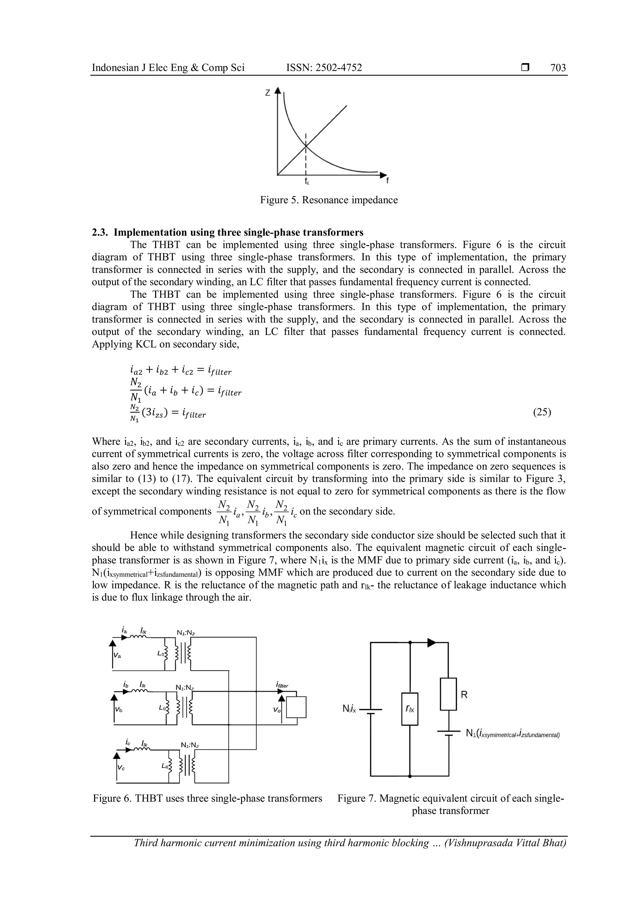
THBT comprises four mutual inductances as shown in Figure 1. Three inductances are connected in
series with every three phases of supply and the fourth winding is connected with a filter. Figure 2 shows the
circuit connection of THBT with single-phase and three-phase loads. THBT can be considered as a
transformer with three primary windings and one secondary winding. Let the secondary be open-circuit and
the primary three windings are in series with three phases for the analysis.
Figure 1. THBT winding
Figure 2. THBT circuit diagram
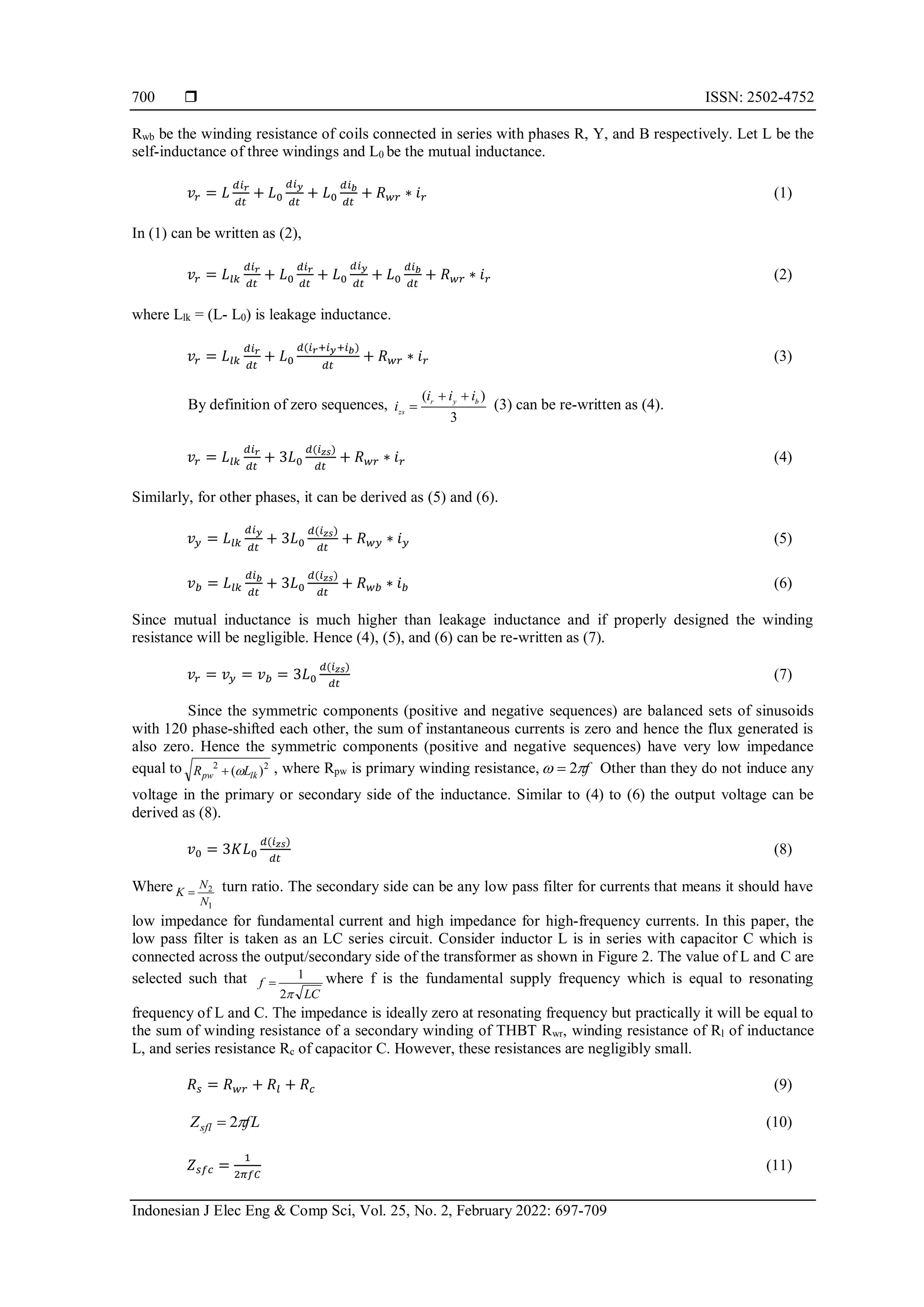
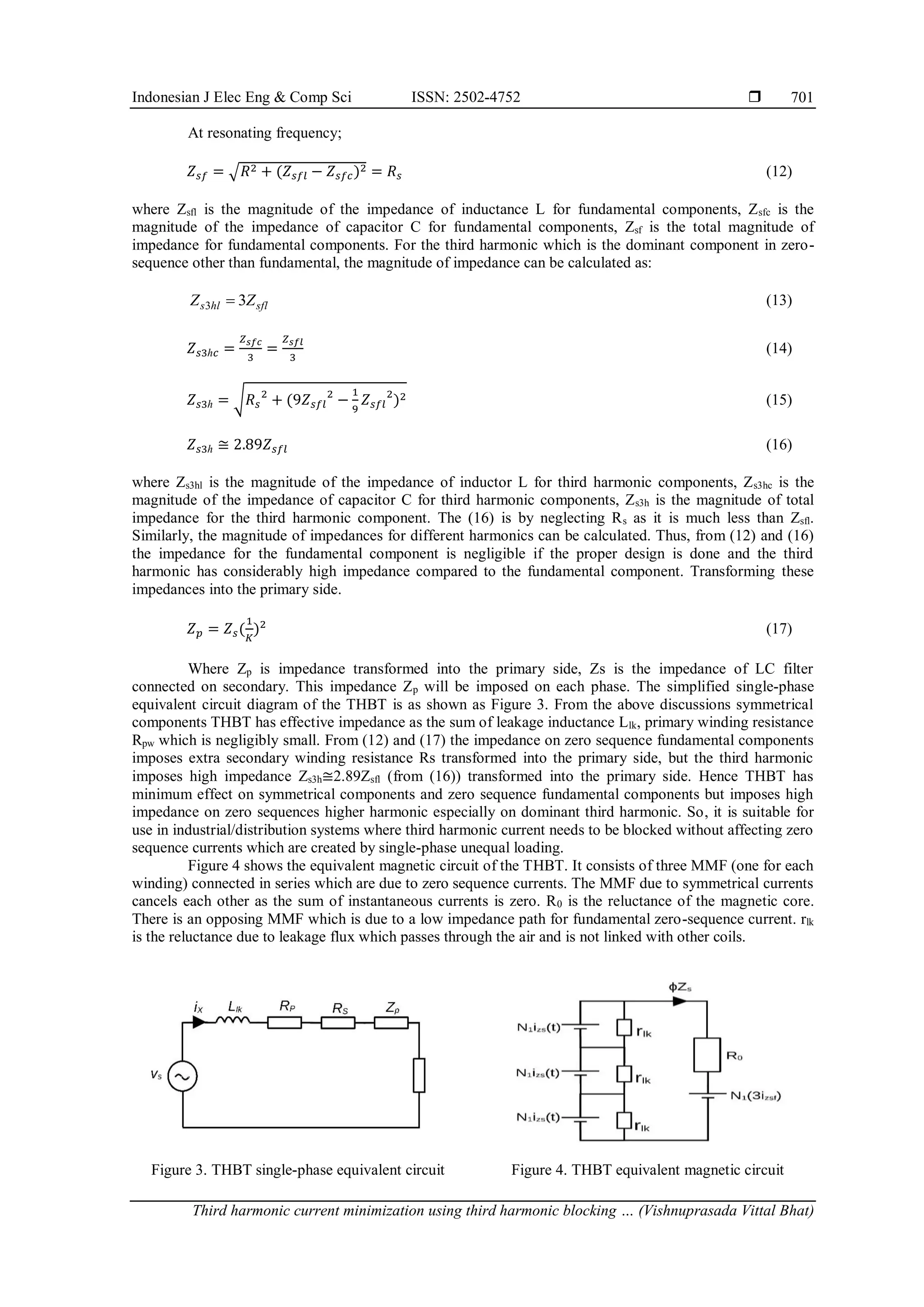
Consider ir, iy and ib be the phase currents and izs be the zero-sequence current. Let vr, vy, and vb be
the voltage across three windings of the THBT, v0 be the voltage across the fourth winding. Let Rwr, Rwy, and](https://image.slidesharecdn.com/26089-51875-1-pb-240517090214-45697db7/75/Third-harmonic-current-minimization-using-third-harmonic-blocking-transformer-3-2048.jpg)

![ ISSN: 2502-4752
Indonesian J Elec Eng & Comp Sci, Vol. 25, No. 2, February 2022: 697-709
708
4. CONCLUSION
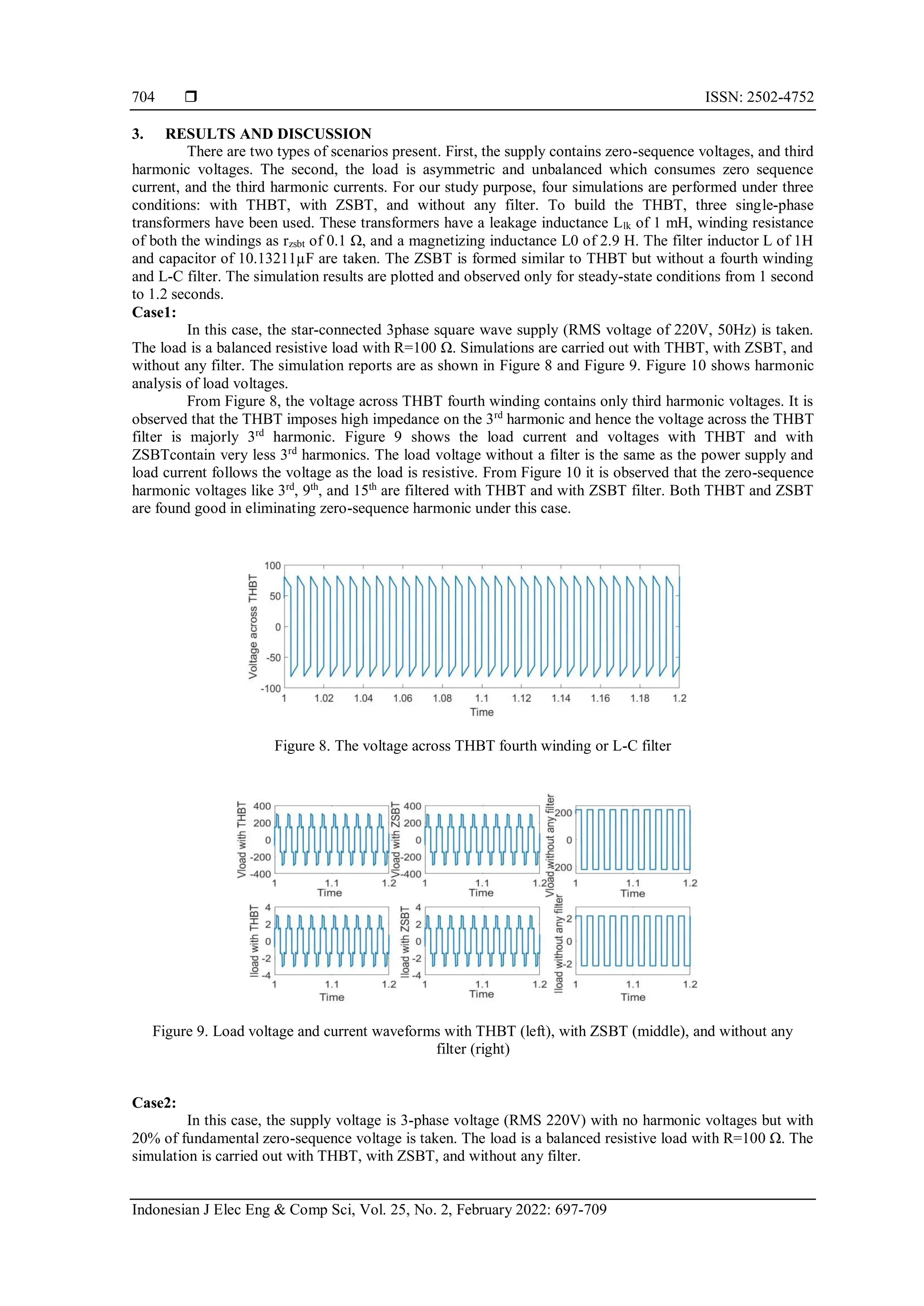
From case1 simulations, it is observed that THBT can be used in 3 phase systems where the supply
has 3rd harmonic voltage. Both THBT and ZSBT are found good in eliminating zero-sequence harmonic
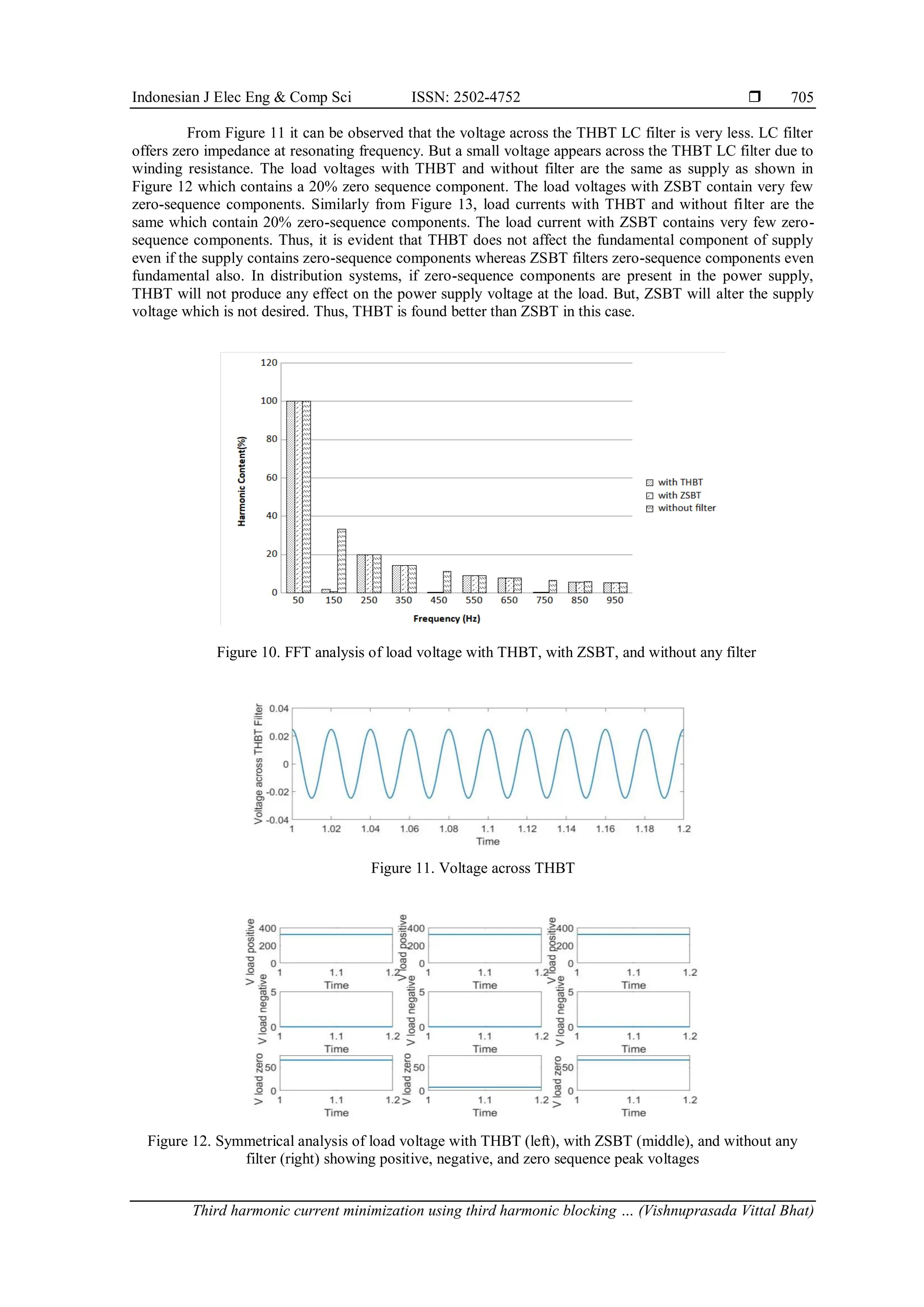
under this case. From case2 simulations, it is clear that the THBT imposes negligible impedance for 3-phase
systems where the supply has fundamental zero-sequence voltage. The same supply voltage appears across
the load without any drop due to fundamental zero-sequence voltage. If zero-sequence components are
present in the power supply, THBT will not produce any effect on the power supply voltage at the load. But,
ZSBT will alter the supply voltage which is not desired. Thus, THBT is found better than ZSBT in this case.
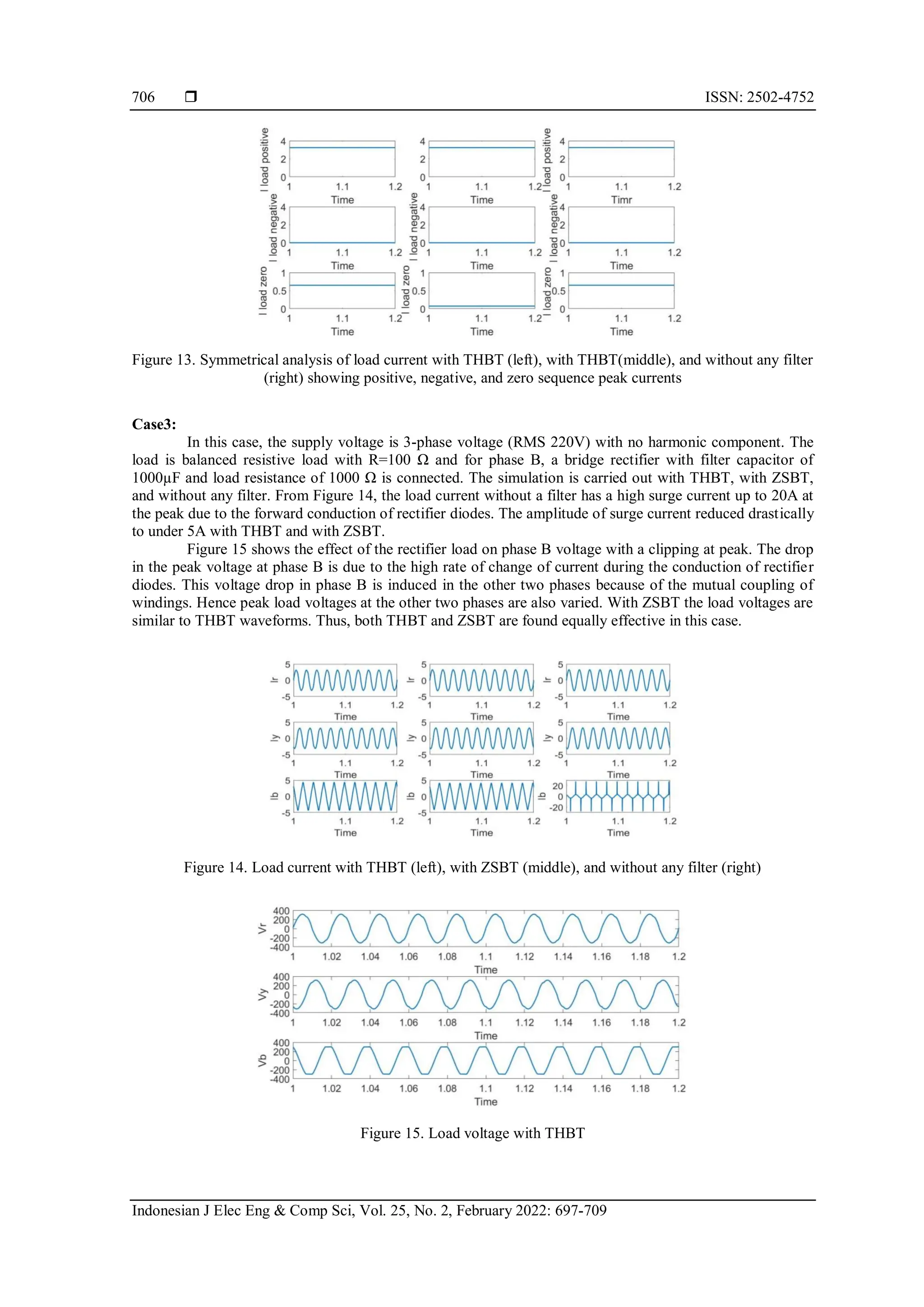
From case3 simulations, it can be observed that, if a non-linear load like bridge rectifier is present at the load,
the THBT suppresses the peak current drastically. But the supply voltage gets distorted at all the phases.
Since THBT is a coupled inductor, the voltage induced due to load current is coupled with all the windings.
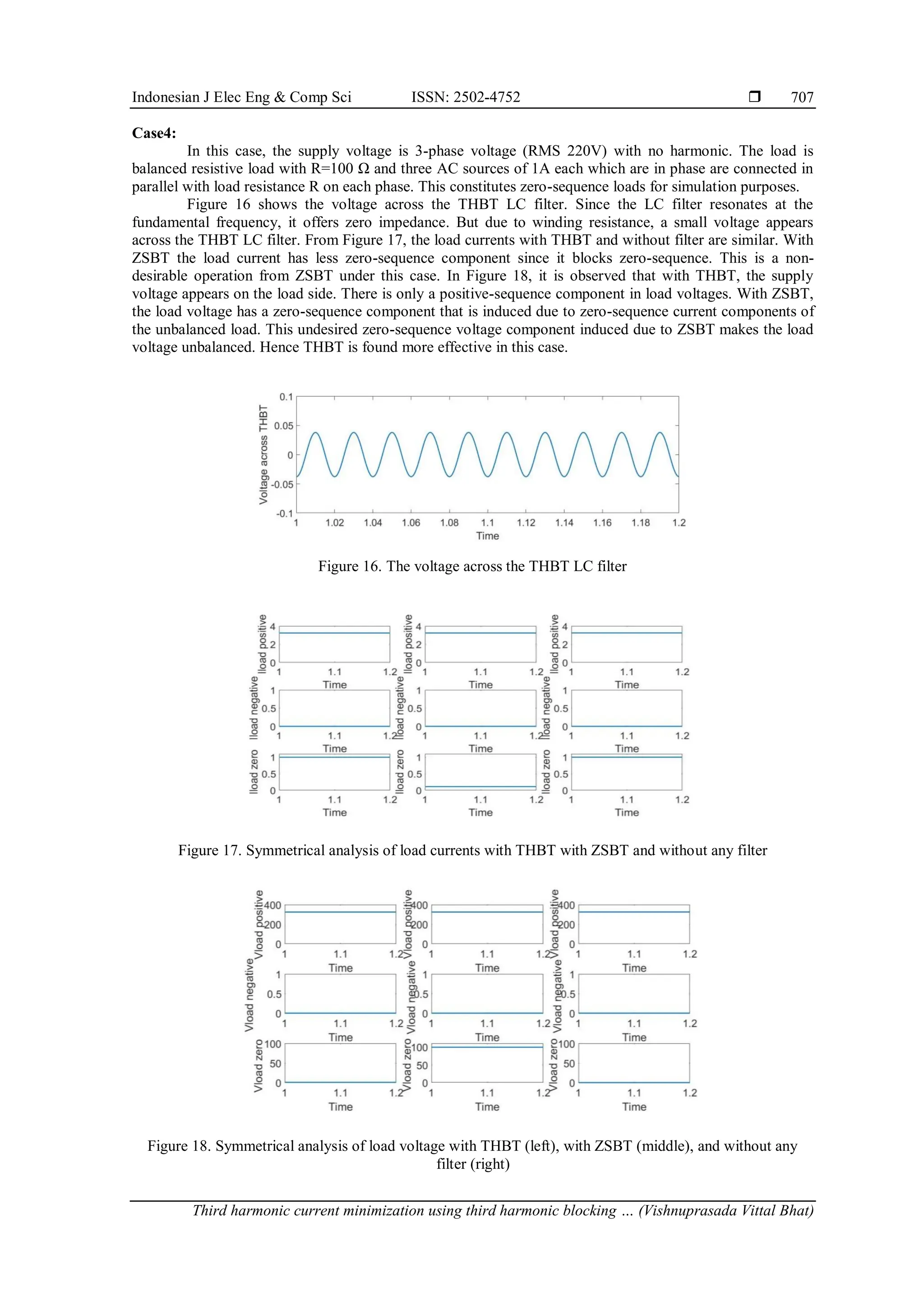
Simulations show that both THBT and ZSBT are found equally effective in this case. From case4
simulations, it can be understood that the THBT does not affect load voltage due to zero sequence
components of load current which usually happens due to single-phase loading in distribution systems. With
ZSBT, the load voltage has a zero-sequence component making the load voltage unbalanced, and also ZSBT
alters load current. Hence THBT is found more effective in this case. Thus THBT is a better option to
minimize third harmonic current in 3-phase systems and to minimize the copper loss in the neutral line.
ACKNOWLEDGEMENTS
The present work has been filed for patent application with the Indian Patent Office Application No.
“202141020237”, Filing Date: May 3, 2021.
REFERENCES
[1] A. Laka, J. A. Barrena, M. A. R. Vidal, and G. Calvo, "Novel Zero-Sequence Blocking Transformer (ZSBT) Using Three Single-
Phase Transformers," IEEE Transactions On Energy Conversion, vol. 28, no. 1, pp. 234-242, 2013, doi:
10.1109/TEC.2012.2229282.
[2] A. Laka, J. A. Barrena, J. C. Zabalza, and G. Calvo, "IP-ZSBT Magnetic Configuration for Parallelization–Serialization of Three-
Phase High Power Converters," IEEE Transactions On Energy Conversion, vol. 29, no. 2, pp. 366-374, 2014, doi:
10.1109/TEC.2014.2304395.
[3] D. A. Paice, "Transformers For Multipulse AC/DC Converters," United States Patent 6,101,113, 8 Aug 2000.
[4] L. Basabe and Aitor, "Transformer for blocking zero sequence components," Europe Patent EP 2 579 280 A1, 10 April 2013.
[5] C. M. Hadzer, S. Masri, and N. Mahamad, "A Study on Zero-passing Transformer in Harmonics Reduction," in National Power
and Energy Conference (PECon), Bangi, Malaysia, 2003, doi: 10.1109/PECON.2003.1437440.
[6] Q. Song, Z. Yin, J. Xue, and L. Zhou, "Zero-Sequence Harmonics Current Minimization Using Zero-Blocking Reactor and Zig-
Zag Transformer," in DRPT, Nanjing, China, 2008, doi: 10.1109/DRPT.2008.4523691.
[7] V. B. Bhavaraju and P. N. Enjeti, "An Active Line Conditioner to Balance Voltages in a Three-phase System," IEEE Transactions
on industrial applications, vol. 32, no. 2, pp. 287-292, 1996, doi: 10.1109/28.491476.
[8] M. Ahmadi, H. Samet, and T. Ghanbari, "Discrimination of internal fault from magnetising inrush current in power transformers
based on sine-wave least-squares curve fitting method," IET Science, Measurement & Technology, vol. 9, no. 1, pp. 73-84, 2015,
doi: 10.1049/iet-smt.2014.0012.
[9] A. M. Kuparev, I. I. Litvinov, and D. V. Baklanov, "Harmonic Analysis of the Currents in the Power Transformer Differential
Protection Circuits in the Cases of External and Internal Faults," In 2018 XIV International Scientific-Technical Conference on
Actual Problems of Electronics Instrument Engineering (APEIE), 2018, pp. 202-209, doi: 10.1109/APEIE.2018.8545971.
[10] M. E. Gamal, H. Dessouki, and A. Lotfy, "Implementation of Transformer Static Differential Relay with Harmonic Blocking.
(Dept. E)," MEJ. Mansoura Engineering Journal, vol. 31, no. 1, pp. 62-66, 2020, doi: 10.21608/BFEMU.2020.129250.
[11] R. P. Medeiros and F. B. Costa, "A wavelet-based transformer differential protection: internal fault detection during inrush
conditions." IEEE Transactions on Power Delivery, vol. 33, no. 6, pp. 2965-2977, 2018, doi: 10.1109/TPWRD.2018.2852485.
[12] K. Behrendt, N. Fischer, and C. Labuschagne, "Considerations for using harmonic blocking and harmonic restraint techniques on
transformer differential relays," In proceedings of the 33rd Annual Western Protective Relay Conference, 2006.
[13] J. O. Aibangbee and S. O. Onohaebi, "Power Transformer Differential Relay Inrush Restraint Setting Applications," IOSR
Journal of Electrical and Electronics Engineering (IOSR-JEEE), vol. 11, no. 1, pp. 68-75, 2016, doi: 10.9790/1676-1101046875.
[14] B. Jiří, and P. Martin, "Transformer inrush-Harmonics in the current." In 2018 19th International Scientific Conference on
Electric Power Engineering (EPE), 2018, pp. 1-4, doi: 10.1109/EPE.2018.8396014.
[15] W. Jiang, W. Ma, J. Wang, W. Wang, X. Zhang, and L. Wang. "Suppression of zero sequence circulating current for parallel
three-phase grid-connected converters using hybrid modulation strategy," IEEE Transactions on Industrial Electronics, vol. 65,
no. 4, pp. 3017-3026, 2017, doi: 10.1109/TIE.2017.2750625.
[16] S. K. Shaikh, A. M. Mulla, S. U. Bagwan, and Y. A. Makandar, "Analysis and Application of Zigzag Transformer in Distribution
System for Mitigation of Triplen Harmonics," In 2020 5th International Conference on Communication and Electronics Systems
(ICCES), 2020, pp. 94-98, doi: 10.1109/ICCES48766.2020.9137857.
[17] A. Rahman, M. M. Rahman, and M. R. Islam, "A study of THD minimization of three phase inverter using modified THPWM,"
In 2017 3rd International Conference on Electrical Information and Communication Technology (EICT), IEEE, pp. 1-4, 2017,
doi: 10.1109/EICT.2017.8275225.
[18] A. M. Eltamaly, "A novel current injection device for harmonic reduction of three-phase controlled converters in renewable
energy utility interfacing," Journal of Renewable and Sustainable Energy, vol. 9, no. 4, p. 045504, 2017, doi: 10.1063/1.4997494.](https://image.slidesharecdn.com/26089-51875-1-pb-240517090214-45697db7/75/Third-harmonic-current-minimization-using-third-harmonic-blocking-transformer-12-2048.jpg)
![Indonesian J Elec Eng & Comp Sci ISSN: 2502-4752
Third harmonic current minimization using third harmonic blocking … (Vishnuprasada Vittal Bhat)
709
[19] M. S. Almutairi and S. Hadjiloucas, "Harmonics Mitigation Based on the Minimization of Non-Linearity Current in a Power
System." Designs, vol. 3, no. 2, p. 29, 2019, doi: 10.3390/designs3020029.
[20] S. L. Gbadamosi, N. I. Nwulu, and Y. Sun, "Harmonic and power loss minimization in power systems incorporating renewable
energy sources and locational marginal pricing," Journal of Renewable and Sustainable Energy, vol. 10, no. 5, p. 055501, 2018,
doi: 10.1063/1.5041923.
[21] A. K. M. Arafat and S. Choi, "Active current harmonic suppression for torque ripple minimization at open-phase faults in a five-
phase PMa-SynRM," IEEE Transactions on Industrial Electronics, vol. 66, no. 2, pp. 922-931, 2018, doi:
10.1109/TIE.2018.2829685.
[22] A. Routray, R. K. Singh, and R. Mahanty, "Harmonic minimization in three-phase hybrid cascaded multilevel inverter using
modified particle swarm optimization," IEEE Transactions on Industrial Informatics, vol. 15, no. 8, pp. 4407-4417, 2018, doi:
10.1109/TII.2018.2883050.
[23] A. Yadav, S. N. Singh, and S. P. Das, "Analysis of transformerless MMC and suppression of third order harmonic current,"
In 2019 National Power Electronics Conference (NPEC), IEEE, 2019, pp. 1-6, doi: 10.1109/NPEC47332.2019.9034733.
[24] A. M. Abd-Elrasool Elagab and I. M. El-Amin, "Minimization of Harmonics Penetration into Transmission and Distribution
Systems by Utilizing Tertiary Winding of the Transformer," In 2017 9th IEEE-GCC Conference and Exhibition (GCCCE), IEEE,
2017, pp. 1-9, doi: 10.1109/IEEEGCC.2017.8448241.
[25] S. Krishnamurthy and B. E. Baningobera, "IEC61850 standard-based harmonic blocking scheme for power
transformers," Protection and Control of Modern Power Systems, vol. 4, no. 1 p. 10, 2019, doi: 10.1186/s41601-019-0123-7.
BIOGRAPHIES OF AUTHORS
Mr. Vishnuprasada Vittal Bhat received B.E. Degree in Electrical and
Electronics in 2006 from NMAMIT, Nitte. He started a manufacturing unit”Swadeshee” of
electronic gadgets in 2007 and did is M-Tech in Power Elctronics in St. Joseph Engineering
College, Vamanjoor in 2014. He continued his business and founded agtech strtup company
“Krishi-Tantra” (Klonec Automation Systems Pvt Ltd) in 2017. His area of interest is Power
electronics, Power systems and Embedded Systems. He has applied for three patents of his
innovations “A Soil Analysis Apparatus” (Application number: 202047035847 A), “An
Electrical Transformer For Suppressing Triplen Harmonic Distortion In Input Electrical Power
And Method Thereof” along with team mates (Application number: 202141020237) and "An
Automated Soil Analysis Apparatus" (Application number: 202141022299) He is engaged as a
research scholar in NMAMIT Nitte. He can be contacted at email: vishnupangala@gmail.com.
Dr. Pinto Pius is the former professor in the department of Electrical and
Electronics Engineering NMAMIT, Nitte. His teaching and research focus is on power
electronics and control systems. He received his B.E. in Electrical Engineering from Mysore
University (1976), M-Tech from Mangalore University (1999) and Ph.D. in Power Electronics
from NITK Surathkal (2008). He has an industrial experience of 26 years and teaching
experience of 13 years. He can be contacted at email: loypinto@yahoo.com, alternative id is
email: pintopaj@nitte.edu.in.](https://image.slidesharecdn.com/26089-51875-1-pb-240517090214-45697db7/75/Third-harmonic-current-minimization-using-third-harmonic-blocking-transformer-13-2048.jpg)