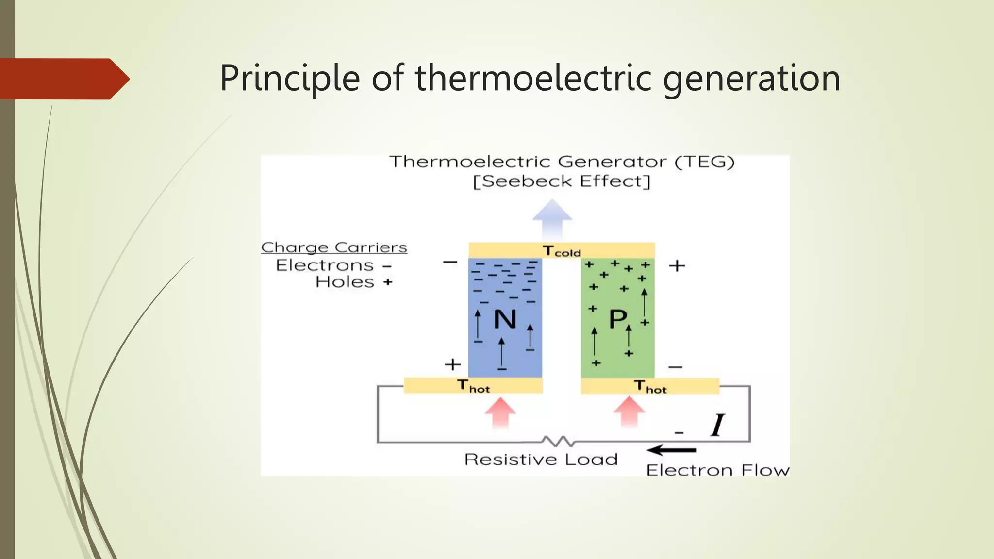
Thermoelectric generator (TEG)
technologies and applications
Supervised by : Majeed Abbasalizadeh
Prepared by : Ahmed Jassim Khalaf
Abstract
 Nowadays humans are facing difficult issues, such as increasing power costs,
environmental pollution and global warming.. Scientists are focusing on enhancing
energy-harvesting power generators in an effort to lessen their effects. Through
the Seebeck effect, thermoelectric generators (TEGs) have proven they are capable
of converting thermal energy directly into electric power. Thermoelectric systems
have arisen during the past ten years as a possible alternative to existing green
energy generation technologies because of the distinctive advantages they provide.
Introduction
 In power plants, about two thirds of the energy used to produce electricity is
wasted as waste heat that is emitted through cooling towers . The primary cause is
that the gas or steam-powered turbine systems, which are responsible for
producing the majority of the electrical power, work largely by burning fuel to
create heat energy, within the turbine, this thermal energy is transformed into
mechanical energy, which is then transformed into electrical energy in a generator
Because of this, only roughly one-third of the fuel's energy is actually transferred to
the transmission lines that leave the power plant.
TEG_working principle Mostly, TEG
systems consist of three key elements
1- A heat exchanger (HEX); This absorbs the heat and transfers it into the
thermoelectric modules.
2- Thermoelectric modules (TEMs); The TEMs generate electricity when a temperature
difference exists between their ends. A TEM contains many pairs of thermoelectric
couples,
3 - A heat sink; In order to dissipate the additional heat from the thermoelectric
modules. The temperature difference between two sides of the generator .
Seebeckeffect
 This mechanism, where a temperature differential produces a voltage, is known as
the thermoelectric effect or Seebeck effect and it was believed to have been
defined for the first time in the 1820s by the German physicist Thomas Johann
Seebeck. However, recent evi- dence shows that Alessandro Volta had also
observed the Seebeck effect 27 years before Thomas Seebeck.
Principle of thermoelectric generation
. Peltiereffect
 As mentioned earlier, in 1821, Thomas Seebeck, a German physi- cist, carried out
numerous tests on electricity and discovered that electricity can function through a
circuit comprising two separate conductors, given that the junctions at which these
conductors con- nected were kept at different temperatures.
Power Generation and Electrical Refrigeration
(Peltier Effect)
Thomsoneffect
 Thomson indicated that as the current passes into unequally heated conductors,
the thermal energy is either consumed or formed in the metal structure ,In other
words, the Thomson effect is the generation of reversible heat when an electrical
current is passed through a conductive material subjected to a temperature
gradient,
Jouleheating

 The heating effect was first studied and categorised by James Pre- scott Joule,
around the year 1840. Joule set out to investigate if the recently invented electrical
motor could be more efficient, in terms of cost, than the steam engines in use at
the time. This led him to con- duct a series of experiments on the production,
transfer and use of energy and mechanical work that ultimately led to the first law
of thermodynamics.
TEG materials, design and optimisation
 As mentioned above, thermoelectric generators offer a reliable solid-state solution
for energy conversion. Devices using advanced thermoelectric materials can
become an alternative to traditional power generation heat engines, most notably
in lightweight heat recovery systems. The maximum efficiency of the conversion of
ther- moelectric energy is typically presented in terms of the temperature of each
heat reservoir and the thermoelectric .
TEG Case Studies and Applications
 Thermoelectricity, in the form of thermoelectric generators, has a strong capacity
for waste heat recovery, and has been researched and demonstrated in a variety of
experimental and theoretical works. Through the use of a thermoelectric generator,
part of the energy that is usually lost during the production operation can be
converted into electricity.
Types of semiconductors used in
thermoelectric generators
 Three materials are commonly used for thermoelectric generators. These materials
are bismuth (Bi2Te3) telluride, lead telluride (PbTe) and Silicon germanium (SiGe).
Which material is used depends on the characteristics of the heat source, cold sink
and the design of the thermoelectric generator. Many thermoelectric generator
materials are currently undergoing research but have not been commercialized.
Challenges of TEG
 The primary challenge of using TEG is its low thermal effi- ciency (typically Ztho4%)
. Thermoelectric materials effi- ciency depends on the thermoelectric figure of
merit, Z; a material constant proportional to the efficiency of a thermoelectric
couple made with the material. stated that future thermoelectric materials show the
promise of reaching signifi- cantly higher values of the thermoelectric figure of
merit, Z, and thus higher efficiencies and power densities can be obtained.
Materials such as BiTe (bismuth telluride), CeFeSb (skutterudite), ZnBe (zinc–
beryllium), SiGe (silicon–germanium), SnTe (tin tell- uride) and new nano-crystalline
or nano-wire thermoelectric materials are currently in development stage to
improve the conversion efficiency of TEG.
TEG in the automotive industry
 For an automobile engine, there are two main exhaust heat gas sources which are
readily available. The radiator and exhaust gas systems are the main heat output of
an IC engine . The radiator system is used to pump the coolant through the cham-
bers in the heat engine block to avoid overheating and seizure . Conversely, the
exhaust gas system of an IC engine is used to discharge the expanded exhaust gas
through the exhaust mani- fold. that presently TEG is mostly installed in the
exhaust gas system (exhaust manifold) due to its simplicity and low influence on
the operation of the engine. Furthermore, TEG system including the heat exchanger
is com- monly installed in the exhaust manifold suitable for its high temperature
region . Basically, a practical automotive waste heat energy recovery system
consists of an exhaust gas system, a heat exchanger, a TEG system, a power
conditioning system, and a battery pack .
Conclusion
 it has been identified that there are large potentials of energy savings through the use of waste
heat recovery technologies. Waste heat recovery entails capturing and reusing the waste heat from
internal combustion engine and using it for heating or generating mechanical or electrical work. It
would also help to recognize the improvement in performance and emissions of the engine if these
technologies were adopted by the automotive manufacturers. T It should be noted that TEG
technology can be incorporated with other technologies such as PV, turbocharger or even Rankine
bottoming cycle technique to maximize energy efficiency, reduce fuel consumption and GHG
emissions. Recovering engine waste heat can be achieved via numerous methods. The heat can
either be ’’reused’’ within the same process or transferred to another thermal, electrical, or
mechanical process. The common technolo- gies used for waste heat recovery from engine include
thermo- electrical devices, organic Rankine cycle or turbocharger system. By maximizing the
potential energy of exhaust gases, engine efficiency and net power may be improved. Exergy
efficiency is a concept which helps to obviously show the environmental impact by numbers. By
increasing the exergy efficiency, sustainability index will increase and leads to less production of
pollutants like NOx and SO2 during creating the same amount of power.
Thanks for listening

Thermoelectric generator .pptx

  • 1.
    Thermoelectric generator (TEG) technologiesand applications Supervised by : Majeed Abbasalizadeh Prepared by : Ahmed Jassim Khalaf
  • 2.
    Abstract  Nowadays humansare facing difficult issues, such as increasing power costs, environmental pollution and global warming.. Scientists are focusing on enhancing energy-harvesting power generators in an effort to lessen their effects. Through the Seebeck effect, thermoelectric generators (TEGs) have proven they are capable of converting thermal energy directly into electric power. Thermoelectric systems have arisen during the past ten years as a possible alternative to existing green energy generation technologies because of the distinctive advantages they provide.
  • 3.
    Introduction  In powerplants, about two thirds of the energy used to produce electricity is wasted as waste heat that is emitted through cooling towers . The primary cause is that the gas or steam-powered turbine systems, which are responsible for producing the majority of the electrical power, work largely by burning fuel to create heat energy, within the turbine, this thermal energy is transformed into mechanical energy, which is then transformed into electrical energy in a generator Because of this, only roughly one-third of the fuel's energy is actually transferred to the transmission lines that leave the power plant.
  • 4.
    TEG_working principle Mostly,TEG systems consist of three key elements 1- A heat exchanger (HEX); This absorbs the heat and transfers it into the thermoelectric modules. 2- Thermoelectric modules (TEMs); The TEMs generate electricity when a temperature difference exists between their ends. A TEM contains many pairs of thermoelectric couples, 3 - A heat sink; In order to dissipate the additional heat from the thermoelectric modules. The temperature difference between two sides of the generator .
  • 5.
    Seebeckeffect  This mechanism,where a temperature differential produces a voltage, is known as the thermoelectric effect or Seebeck effect and it was believed to have been defined for the first time in the 1820s by the German physicist Thomas Johann Seebeck. However, recent evi- dence shows that Alessandro Volta had also observed the Seebeck effect 27 years before Thomas Seebeck.
  • 6.
  • 7.
    . Peltiereffect  Asmentioned earlier, in 1821, Thomas Seebeck, a German physi- cist, carried out numerous tests on electricity and discovered that electricity can function through a circuit comprising two separate conductors, given that the junctions at which these conductors con- nected were kept at different temperatures.
  • 8.
    Power Generation andElectrical Refrigeration (Peltier Effect)
  • 9.
    Thomsoneffect  Thomson indicatedthat as the current passes into unequally heated conductors, the thermal energy is either consumed or formed in the metal structure ,In other words, the Thomson effect is the generation of reversible heat when an electrical current is passed through a conductive material subjected to a temperature gradient,
  • 10.
    Jouleheating   The heatingeffect was first studied and categorised by James Pre- scott Joule, around the year 1840. Joule set out to investigate if the recently invented electrical motor could be more efficient, in terms of cost, than the steam engines in use at the time. This led him to con- duct a series of experiments on the production, transfer and use of energy and mechanical work that ultimately led to the first law of thermodynamics.
  • 11.
    TEG materials, designand optimisation  As mentioned above, thermoelectric generators offer a reliable solid-state solution for energy conversion. Devices using advanced thermoelectric materials can become an alternative to traditional power generation heat engines, most notably in lightweight heat recovery systems. The maximum efficiency of the conversion of ther- moelectric energy is typically presented in terms of the temperature of each heat reservoir and the thermoelectric .
  • 12.
    TEG Case Studiesand Applications  Thermoelectricity, in the form of thermoelectric generators, has a strong capacity for waste heat recovery, and has been researched and demonstrated in a variety of experimental and theoretical works. Through the use of a thermoelectric generator, part of the energy that is usually lost during the production operation can be converted into electricity.
  • 13.
    Types of semiconductorsused in thermoelectric generators  Three materials are commonly used for thermoelectric generators. These materials are bismuth (Bi2Te3) telluride, lead telluride (PbTe) and Silicon germanium (SiGe). Which material is used depends on the characteristics of the heat source, cold sink and the design of the thermoelectric generator. Many thermoelectric generator materials are currently undergoing research but have not been commercialized.
  • 14.
    Challenges of TEG The primary challenge of using TEG is its low thermal effi- ciency (typically Ztho4%) . Thermoelectric materials effi- ciency depends on the thermoelectric figure of merit, Z; a material constant proportional to the efficiency of a thermoelectric couple made with the material. stated that future thermoelectric materials show the promise of reaching signifi- cantly higher values of the thermoelectric figure of merit, Z, and thus higher efficiencies and power densities can be obtained. Materials such as BiTe (bismuth telluride), CeFeSb (skutterudite), ZnBe (zinc– beryllium), SiGe (silicon–germanium), SnTe (tin tell- uride) and new nano-crystalline or nano-wire thermoelectric materials are currently in development stage to improve the conversion efficiency of TEG.
  • 15.
    TEG in theautomotive industry  For an automobile engine, there are two main exhaust heat gas sources which are readily available. The radiator and exhaust gas systems are the main heat output of an IC engine . The radiator system is used to pump the coolant through the cham- bers in the heat engine block to avoid overheating and seizure . Conversely, the exhaust gas system of an IC engine is used to discharge the expanded exhaust gas through the exhaust mani- fold. that presently TEG is mostly installed in the exhaust gas system (exhaust manifold) due to its simplicity and low influence on the operation of the engine. Furthermore, TEG system including the heat exchanger is com- monly installed in the exhaust manifold suitable for its high temperature region . Basically, a practical automotive waste heat energy recovery system consists of an exhaust gas system, a heat exchanger, a TEG system, a power conditioning system, and a battery pack .
  • 16.
    Conclusion  it hasbeen identified that there are large potentials of energy savings through the use of waste heat recovery technologies. Waste heat recovery entails capturing and reusing the waste heat from internal combustion engine and using it for heating or generating mechanical or electrical work. It would also help to recognize the improvement in performance and emissions of the engine if these technologies were adopted by the automotive manufacturers. T It should be noted that TEG technology can be incorporated with other technologies such as PV, turbocharger or even Rankine bottoming cycle technique to maximize energy efficiency, reduce fuel consumption and GHG emissions. Recovering engine waste heat can be achieved via numerous methods. The heat can either be ’’reused’’ within the same process or transferred to another thermal, electrical, or mechanical process. The common technolo- gies used for waste heat recovery from engine include thermo- electrical devices, organic Rankine cycle or turbocharger system. By maximizing the potential energy of exhaust gases, engine efficiency and net power may be improved. Exergy efficiency is a concept which helps to obviously show the environmental impact by numbers. By increasing the exergy efficiency, sustainability index will increase and leads to less production of pollutants like NOx and SO2 during creating the same amount of power.
  • 17.