Downloaded 213 times
![VIII
“To contribute significantly in strengthening India in the power sector and become the
world’s most valuable and reliant thermal power service providing company”
2.2 MISSION OF PPGCL
“To provide a world class distinguished service,focussed on adding value to the customers process,
whilst addressing customer`s needs in a professional and dynamic manner.”
2.3 TARGET AND CHALLENGES
2.3.1 [TARGET]
The project is being built by Prayagraj Power Generation, a power generation subsidiary of the
privately owned Jaypee Group, a major Indian infrastructure company with interests in Civil
Engineering and Construction, Cement, Power, Real Estate, Expressways, Hospitality, Golf Courses
and Education. According to Jaypee Group (2011), the project will be built in two Phases. Phase 1,
comprising three 660 MW units, is slated to be commissioned in 2015. JPV bought the Prayagraj
Power Generation Company, a special purpose project company created by the Uttar Pradesh Power
Corporation to build the Bara project on a 'build, own, operate' basis.
According to the 2010/2011 annual report, the company was in possession of the 778 hectares
needed for the project and had received the necessary environmental clearance, water linkage, and
coal linkage. Boiler foundations were completed and other construction works was underway.
Financial closure had been achieved.
According to the JP Power Ventures website (2014), Phase I is planned for completion by
2014. However, as of 2015 Phase I is under construction with Unit 1 planned for October 2015 and
units 2-3 in 2016, according to the India Central Electrical Authority.
Phase II would comprise two 660 MW units. As of August 2015 phase II has yet to receive
environmental permits, and appears to be deferred or abandoned.
.
2.3.2 [Challenge]
Both the Bara project and the nearby Karchana Thermal Power Project (now cancelled) have been
the subject of local opposition and agitation. The Environmental Justice Atlas reported that protests
at the Bara project in January 2011 damaged "police vehicles to protest against land acquisition
policies." Additionally, protesters claimed one farmer was killed in police firing, a charge denied by
the Uttar Pradesh government. It was reported in February 2011 that villagers ransacked and
damaged property at the project site. The protesters had reportedly inflicted damage worth Rs 1
crore.
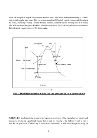
3. ABOUT THE COMPANY](https://image.slidesharecdn.com/ravinderjangidtrainingreport-151209143449-lva1-app6891/85/Industrial-training-report-of-thermal-power-plant-8-320.jpg)

This document provides details from a student's industrial training report on boiler, turbine, and generator operation and maintenance at PPGCL power plant in India. It includes: 1. An introduction to the benefits of industrial training. 2. Vision, mission, targets, and challenges of PPGCL including increasing plant efficiency and facing local opposition during construction. 3. Descriptions of the basic Rankine power cycle, components and specifications of the plant's boiler, turbine, and generator systems. 4. Ways to increase plant efficiency such as lowering condenser pressure and increasing steam superheating and boiler pressure.


