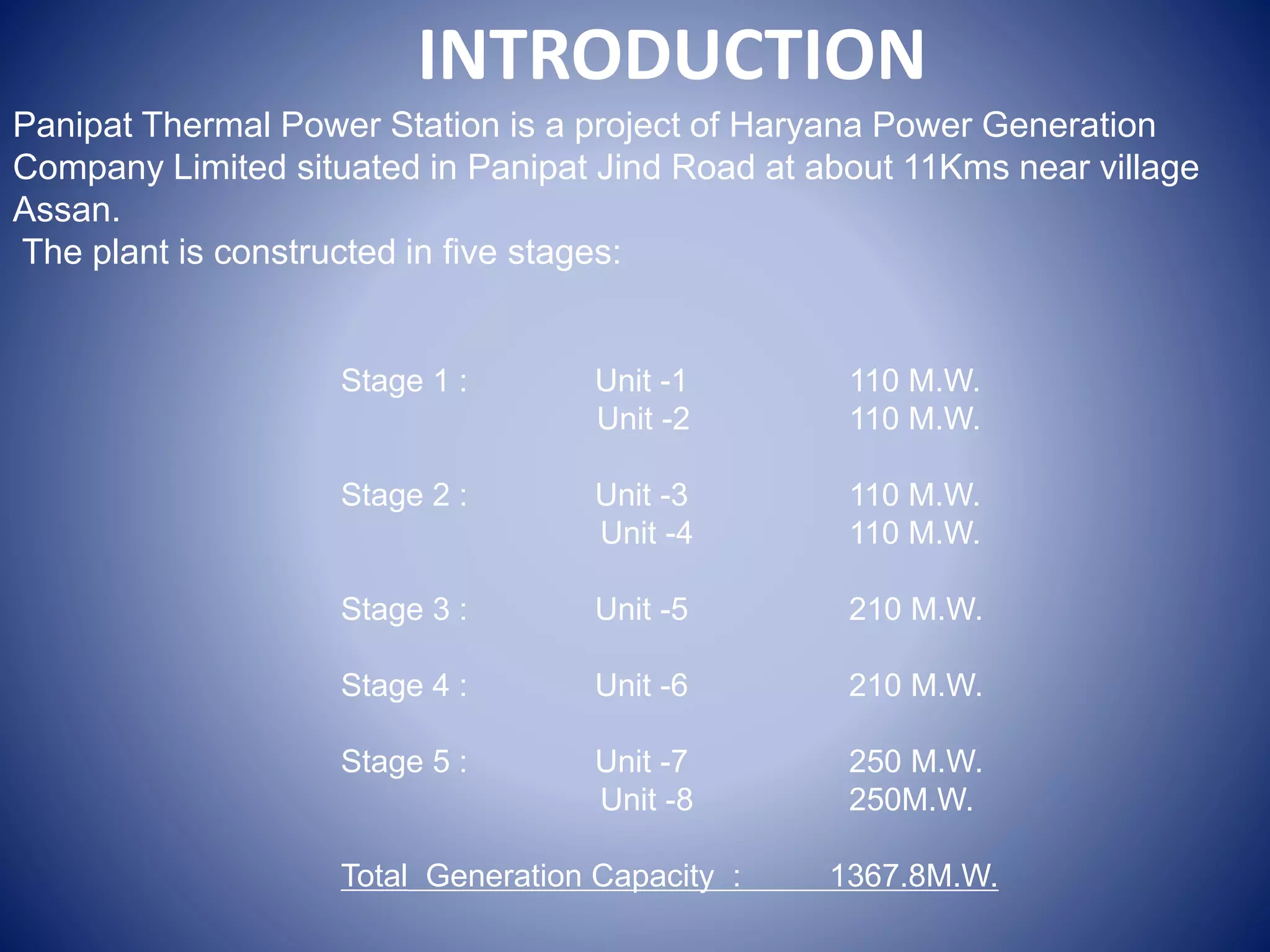
TRANING REPORT
ON
PANIPAT THERMAL POWER PLANT
SAHILARORA
1213422
INTRODUCTION
Stage 1 : Unit -1 110 M.W.
Unit -2 110 M.W.
Stage 2 : Unit -3 110 M.W.
Unit -4 110 M.W.
Stage 3 : Unit -5 210 M.W.
Stage 4 : Unit -6 210 M.W.
Stage 5 : Unit -7 250 M.W.
Unit -8 250M.W.
Total Generation Capacity : 1367.8M.W.
Panipat Thermal Power Station is a project of Haryana Power Generation
Company Limited situated in Panipat Jind Road at about 11Kms near village
Assan.
The plant is constructed in five stages:
Basic Idea of Electricity
Generation
Coal is unloaded by electric traction system at Coal Yard
Coal is crushed to finer pieces of order 20 mm
Pulverization of Coal
Coal is send to furnace with the help of FD fan
Steam is generated at 540°C and 135 kg/sq.m
Steam is send to Super heater
Superheated steam is send to turbine
Production of Electricity by the generator coupled with
Thermal Power Plant
• Thermal power plants are used to convert the heat energy of
coal into electrical energy . Coal is burnt in a boiler which
converts water into steam . The expansion of steam in turbine
produces mechanical power which drives alternator coupled
to the turbine . Thermal power plants contribute maximum to
the generation of power for any country.
• Therma power plants consitiute 75.43% of the total installed
captive and non captive power generation in India.
• In thermal generating stations coal, oil, natural gas are
employed as primary sources of energy.
THREE MAJOR INPUTS TO POWER STATIONS
1) Water:
Water has been taken from near by Yamuna Canal. This water is lifted by raw water pumps and is sent to clarifier
to remove turbidity of water. The clear water is sent to water treatment plant, cooling water system and
service water system. The water is dematerialized (DM) by water treatment plant. The DM water is stored in
condensate storage tanks from where it is used in boiler.
2) Fuel Oil :
The fuel oil used is of two types:
.Low sulphate high stock oil (LSHS)
.High speed diesel oil (HSD)
The high speed diesel oil reaches the power station through the lorry tankers. The oil is stored in large tanks for the
future use in the boiler . Heavy oil is stored in storage tanks in oil storage yard and is conveyed to the front through
a set of pumps and Strainers.
3) COAL:
The coal reaches the plant in the railway wagons. The unloading of coal is done mechanically by tilting the wagons
by tippler. The coal is sent to the coal storage yard through the conveyer belts. The crushed coal from store is sent
to the mill bunkers through conveyer belts.
COAL FEEDING SYSTEM
Coal is conveyed through rail wagon from out side of plant
and through conveyor system collected in hopper and
ground to a very fine powder by large metal spheres in the
pulverised fuel mill.
Conveyor Coal Hopper
Pulverised Mill
Wagon Tippler
COAL FEEDING SYSTEM
Then it is mixed with preheated air driven by the forced draught fan. The hot air-fuel
mixture is forced at high pressure into the boiler.
Air Pre-heater Forced Draft Fan
BOILER
A boiler or steam generator is a device used to
create steam by applying heat energy to water.
The steam generator or boiler is an integral component of a steam engine when
considered as a prime mover; The boiler is a furnace on a side. Its walls are made of a
web of high pressure steel tubes.
Pulverized coal is air-blown into the furnace from fuel nozzles at the four corners and it
rapidly burns, forming a large fireball at the center. The thermal radiation of the fireball
heats the water that circulates through the boiler tubes near the boiler perimeter. The
water circulation rate in the boiler is three to four times the throughput and is typically
driven by pumps. As the water in the boiler circulates it absorbs heat and changes into
steam at 700 °F (371 °C) and 3,200 psi . It is separated from the water inside a drum at
the top of the furnace.
ASH HANDLING SYSTEM
At the bottom of the furnace, there is a hopper for collection of
bottom ash. This hopper is always filled with water to quench the
ash and clinkers falling down from the furnace. Some
arrangement is included to crush the clinkers and for conveying
the crushed clinkers and bottom ash to a storage site.
SUPER HEATER
In a power plant, after the steam is conditioned by the drying equipment inside the
steam drum, it is piped from the upper drum area into tubes inside an area of the
furnace known as the super heater, which has an elaborate set up of tubing where the
steam vapor picks up more energy from hot flue gases outside the tubing and its
temperature is now superheated above the saturation temperature. The superheated
steam is then piped through the main steam lines to the valves before the high pressure
turbine.
Superheated steam is steam at a
temperature higher than water's boiling
point. If saturated stream is heated at
constant pressure, it increases toward 100%
Dry Saturated Steam. Continued heat input
will then generate superheated steam. This
will occur if saturated steam contacts a
surface with a higher temperature. The
steam is then described as superheated by
the number of degrees it has been heated
above saturation temperature
STEAM TURBINE
The hot reheat steam is conducted to the intermediate pressure turbine where it falls in
both temperature and pressure and exits directly to the long-bladed low pressure
turbines and finally exits to the condense
A steam turbine is a mechanical device that
extracts thermal energy from pressurized
steam, and converts it into rotary motion.
The steam turbine is a form of heat engine
that derives much of its improvement in
thermodynamics efficiency through the use
of multiple stages in the expansion of the
steam.
ROTORS
Type of Oil Pumps:
1. Main Oil Pump (MOP): The MOP is situated in the front bearing pedestal and supplies the entire
turbine with oil i.e. used for bearing lubrication, cooling the shaft journal and thrust bearing. It is driven
by the turbine and develops the rated discharge pressure at 90-95% rated speed. The main pump is
sized tot eh meet the normal requirements of Lubrication, Seal Oil and Governing System.
2. Auxiliary Oil Pump (AOP): It supplies the oil requirements of the turbo set during start-ups
and shutdowns. The oil pump can either be switched on manually or automatically through pressure
switches, which operate when the oil pressure drops to approximately 60% of the normal value.
The setting of the pressure switches is staggered so that one pump comes into operation
before the other one with second one remaining in reserve. The pump continues to remain available
for emergency service through the automatic control system. It is stopped after the turbo generator
set has come to full speed and main oil pump has taken over.
Turbine Oil System
Mineral oil with additives (for increasing the resistance to corrosion and aging) is used as a fluid for
actuating the governing system, lubrication of bearings and seal oil to generator seals. During normal
operation the main oil pump supplies oil at pressure 8 bar approx. to the lubrication seal oil system and
governing system. The oil system fulfills the following functions:
•Lubricating and cooling the bearings.
•Driving the hydraulic turning gear during interruption operation, on startup and shutdown.
•Jacking up the shaft at low speed.
3. D.C. Emergency Oil Pump (EOP): It is standby pump, which can be started manually or automatically
through pressure switch when the tube oil pressure drops to 50% of the normal value. This happens
only when main and auxiliary pumps fail to operate or there is a break down in the electricity supply
system to the pumps. This pump should therefore be fed from station batteries. It has to be in
operation and cater to the need of bearing lubrication and cooling of journals.
4. Jacking Oil Pump (JOP): When the set is stationary, the shafts come into metallic contact with the
bottom bearing lining. The normal bearing oil supply at low speeds is unable to penetrate to these
surfaces and considerable force is required to initiate rotation of the shaft from rest. This is overcome
by forcing high pressure oil through bottom bearing shell, thereby lifting the shaft in the bearings and
allowing an oil film to form. Now shaft can be set in motion by application of considerably smaller force.
This is a high pressure and low discharge pump.
Condenser is a device or unit used to condense a substance from its gaseous to its liquid
state, typically by cooling it.
The exiting steam from steam turbine, now a little above its boiling point, is brought
into thermal contact with cold water (pumped in from the cooling tower) in the
condenser. where it condenses rapidly back into water, creating near vacuum-like
conditions inside the condenser chest.
Water Cooled Condenser Air Cooled Condenser
CONDENSER
Cooling towers are heat removal devices used to transfer process waste heat to the
atmosphere. Cooling towers either use the evaporation of water to remove process
heat and cool the working fluid or in the case of closed circuit dry cooling towers rely
solely on air to cool the working fluid.
Natural Draft Cooling
Tower
COOLING TOWER
ECONOMISER
Economiser
Pre-warmed water first enter in a feed heater
powered by steam drawn from the high pressure
set, and then in the economiser .
Economizer are mechanical devices intended to
reduce energy consumption, or to perform
another useful function like preheating a fluid.
Economizer is a flue gas to water heat exchanger. Usually it is located below the LPSH in
the boiler and above Air pre heater. Outside surface of the economizer tubes are heated
by flue gases leaving the superheater and reheater which subsequently transfer heat to
feed water flowing inside the tubes.
Advantages of Economizer include
1) Fuel economy: – used to save fuel and increase overall efficiency of boiler plant.
2) Reducing size of boiler: – as the feed water is preheated in the economizer and enter
boiler tube at elevated temperature. The heat transfer area required for evaporation
reduced considerably.
Exhaust gas from electrostatic precipitator vented through the chimney tack.
A chimney is a structure for venting hot gases
or smoke from a boiler, furnace or fireplace to
the outside atmosphere.
A chimney is a vertical structure for venting hot
flue gases or smoke from a boiler to the outside
atmosphere by means of the stack effect. The
space inside a chimney is called aflue. The
height of chimneys plays a role in their ability to
transfer flue gases using stack effect. The
dispersion of pollutants at higher altitude helps
to ease down its influence on surroundings and
reduces their concentrations in compliance
with regulatory limits.
CHIMNEY
SWITCHYARD
A switch yard is a part of an electrical generation, transmission,
system. Switchyard transform voltage from high to low,
or the reverse, or perform any of several other important functions.
CONTROL ROOM
A control room is a room serving as a centre where a large physical
facility or physically dispersed service can be monitored and controll
THANK YOU

thermal power plant

  • 1.
    TRANING REPORT ON PANIPAT THERMALPOWER PLANT SAHILARORA 1213422
  • 2.
    INTRODUCTION Stage 1 :Unit -1 110 M.W. Unit -2 110 M.W. Stage 2 : Unit -3 110 M.W. Unit -4 110 M.W. Stage 3 : Unit -5 210 M.W. Stage 4 : Unit -6 210 M.W. Stage 5 : Unit -7 250 M.W. Unit -8 250M.W. Total Generation Capacity : 1367.8M.W. Panipat Thermal Power Station is a project of Haryana Power Generation Company Limited situated in Panipat Jind Road at about 11Kms near village Assan. The plant is constructed in five stages:
  • 3.
    Basic Idea ofElectricity Generation Coal is unloaded by electric traction system at Coal Yard Coal is crushed to finer pieces of order 20 mm Pulverization of Coal Coal is send to furnace with the help of FD fan Steam is generated at 540°C and 135 kg/sq.m Steam is send to Super heater Superheated steam is send to turbine Production of Electricity by the generator coupled with
  • 4.
    Thermal Power Plant •Thermal power plants are used to convert the heat energy of coal into electrical energy . Coal is burnt in a boiler which converts water into steam . The expansion of steam in turbine produces mechanical power which drives alternator coupled to the turbine . Thermal power plants contribute maximum to the generation of power for any country. • Therma power plants consitiute 75.43% of the total installed captive and non captive power generation in India. • In thermal generating stations coal, oil, natural gas are employed as primary sources of energy.
  • 7.
    THREE MAJOR INPUTSTO POWER STATIONS 1) Water: Water has been taken from near by Yamuna Canal. This water is lifted by raw water pumps and is sent to clarifier to remove turbidity of water. The clear water is sent to water treatment plant, cooling water system and service water system. The water is dematerialized (DM) by water treatment plant. The DM water is stored in condensate storage tanks from where it is used in boiler. 2) Fuel Oil : The fuel oil used is of two types: .Low sulphate high stock oil (LSHS) .High speed diesel oil (HSD) The high speed diesel oil reaches the power station through the lorry tankers. The oil is stored in large tanks for the future use in the boiler . Heavy oil is stored in storage tanks in oil storage yard and is conveyed to the front through a set of pumps and Strainers. 3) COAL: The coal reaches the plant in the railway wagons. The unloading of coal is done mechanically by tilting the wagons by tippler. The coal is sent to the coal storage yard through the conveyer belts. The crushed coal from store is sent to the mill bunkers through conveyer belts.
  • 9.
    COAL FEEDING SYSTEM Coalis conveyed through rail wagon from out side of plant and through conveyor system collected in hopper and ground to a very fine powder by large metal spheres in the pulverised fuel mill. Conveyor Coal Hopper Pulverised Mill Wagon Tippler
  • 10.
    COAL FEEDING SYSTEM Thenit is mixed with preheated air driven by the forced draught fan. The hot air-fuel mixture is forced at high pressure into the boiler. Air Pre-heater Forced Draft Fan
  • 11.
    BOILER A boiler orsteam generator is a device used to create steam by applying heat energy to water. The steam generator or boiler is an integral component of a steam engine when considered as a prime mover; The boiler is a furnace on a side. Its walls are made of a web of high pressure steel tubes. Pulverized coal is air-blown into the furnace from fuel nozzles at the four corners and it rapidly burns, forming a large fireball at the center. The thermal radiation of the fireball heats the water that circulates through the boiler tubes near the boiler perimeter. The water circulation rate in the boiler is three to four times the throughput and is typically driven by pumps. As the water in the boiler circulates it absorbs heat and changes into steam at 700 °F (371 °C) and 3,200 psi . It is separated from the water inside a drum at the top of the furnace.
  • 12.
    ASH HANDLING SYSTEM Atthe bottom of the furnace, there is a hopper for collection of bottom ash. This hopper is always filled with water to quench the ash and clinkers falling down from the furnace. Some arrangement is included to crush the clinkers and for conveying the crushed clinkers and bottom ash to a storage site.
  • 13.
    SUPER HEATER In apower plant, after the steam is conditioned by the drying equipment inside the steam drum, it is piped from the upper drum area into tubes inside an area of the furnace known as the super heater, which has an elaborate set up of tubing where the steam vapor picks up more energy from hot flue gases outside the tubing and its temperature is now superheated above the saturation temperature. The superheated steam is then piped through the main steam lines to the valves before the high pressure turbine. Superheated steam is steam at a temperature higher than water's boiling point. If saturated stream is heated at constant pressure, it increases toward 100% Dry Saturated Steam. Continued heat input will then generate superheated steam. This will occur if saturated steam contacts a surface with a higher temperature. The steam is then described as superheated by the number of degrees it has been heated above saturation temperature
  • 14.
    STEAM TURBINE The hotreheat steam is conducted to the intermediate pressure turbine where it falls in both temperature and pressure and exits directly to the long-bladed low pressure turbines and finally exits to the condense A steam turbine is a mechanical device that extracts thermal energy from pressurized steam, and converts it into rotary motion. The steam turbine is a form of heat engine that derives much of its improvement in thermodynamics efficiency through the use of multiple stages in the expansion of the steam.
  • 16.
  • 17.
    Type of OilPumps: 1. Main Oil Pump (MOP): The MOP is situated in the front bearing pedestal and supplies the entire turbine with oil i.e. used for bearing lubrication, cooling the shaft journal and thrust bearing. It is driven by the turbine and develops the rated discharge pressure at 90-95% rated speed. The main pump is sized tot eh meet the normal requirements of Lubrication, Seal Oil and Governing System. 2. Auxiliary Oil Pump (AOP): It supplies the oil requirements of the turbo set during start-ups and shutdowns. The oil pump can either be switched on manually or automatically through pressure switches, which operate when the oil pressure drops to approximately 60% of the normal value. The setting of the pressure switches is staggered so that one pump comes into operation before the other one with second one remaining in reserve. The pump continues to remain available for emergency service through the automatic control system. It is stopped after the turbo generator set has come to full speed and main oil pump has taken over. Turbine Oil System Mineral oil with additives (for increasing the resistance to corrosion and aging) is used as a fluid for actuating the governing system, lubrication of bearings and seal oil to generator seals. During normal operation the main oil pump supplies oil at pressure 8 bar approx. to the lubrication seal oil system and governing system. The oil system fulfills the following functions: •Lubricating and cooling the bearings. •Driving the hydraulic turning gear during interruption operation, on startup and shutdown. •Jacking up the shaft at low speed.
  • 18.
    3. D.C. EmergencyOil Pump (EOP): It is standby pump, which can be started manually or automatically through pressure switch when the tube oil pressure drops to 50% of the normal value. This happens only when main and auxiliary pumps fail to operate or there is a break down in the electricity supply system to the pumps. This pump should therefore be fed from station batteries. It has to be in operation and cater to the need of bearing lubrication and cooling of journals. 4. Jacking Oil Pump (JOP): When the set is stationary, the shafts come into metallic contact with the bottom bearing lining. The normal bearing oil supply at low speeds is unable to penetrate to these surfaces and considerable force is required to initiate rotation of the shaft from rest. This is overcome by forcing high pressure oil through bottom bearing shell, thereby lifting the shaft in the bearings and allowing an oil film to form. Now shaft can be set in motion by application of considerably smaller force. This is a high pressure and low discharge pump.
  • 19.
    Condenser is adevice or unit used to condense a substance from its gaseous to its liquid state, typically by cooling it. The exiting steam from steam turbine, now a little above its boiling point, is brought into thermal contact with cold water (pumped in from the cooling tower) in the condenser. where it condenses rapidly back into water, creating near vacuum-like conditions inside the condenser chest. Water Cooled Condenser Air Cooled Condenser CONDENSER
  • 20.
    Cooling towers areheat removal devices used to transfer process waste heat to the atmosphere. Cooling towers either use the evaporation of water to remove process heat and cool the working fluid or in the case of closed circuit dry cooling towers rely solely on air to cool the working fluid. Natural Draft Cooling Tower COOLING TOWER
  • 21.
    ECONOMISER Economiser Pre-warmed water firstenter in a feed heater powered by steam drawn from the high pressure set, and then in the economiser . Economizer are mechanical devices intended to reduce energy consumption, or to perform another useful function like preheating a fluid. Economizer is a flue gas to water heat exchanger. Usually it is located below the LPSH in the boiler and above Air pre heater. Outside surface of the economizer tubes are heated by flue gases leaving the superheater and reheater which subsequently transfer heat to feed water flowing inside the tubes. Advantages of Economizer include 1) Fuel economy: – used to save fuel and increase overall efficiency of boiler plant. 2) Reducing size of boiler: – as the feed water is preheated in the economizer and enter boiler tube at elevated temperature. The heat transfer area required for evaporation reduced considerably.
  • 22.
    Exhaust gas fromelectrostatic precipitator vented through the chimney tack. A chimney is a structure for venting hot gases or smoke from a boiler, furnace or fireplace to the outside atmosphere. A chimney is a vertical structure for venting hot flue gases or smoke from a boiler to the outside atmosphere by means of the stack effect. The space inside a chimney is called aflue. The height of chimneys plays a role in their ability to transfer flue gases using stack effect. The dispersion of pollutants at higher altitude helps to ease down its influence on surroundings and reduces their concentrations in compliance with regulatory limits. CHIMNEY
  • 23.
    SWITCHYARD A switch yardis a part of an electrical generation, transmission, system. Switchyard transform voltage from high to low, or the reverse, or perform any of several other important functions.
  • 24.
    CONTROL ROOM A controlroom is a room serving as a centre where a large physical facility or physically dispersed service can be monitored and controll
  • 26.