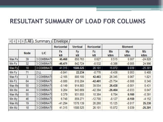
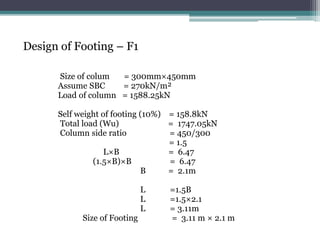
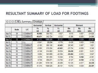
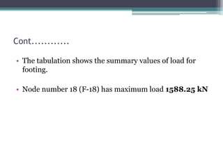
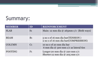
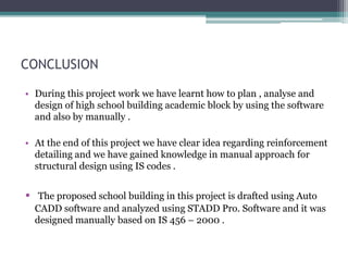
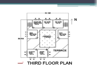
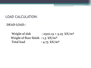
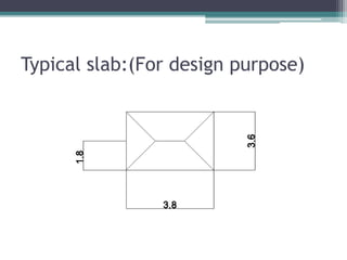
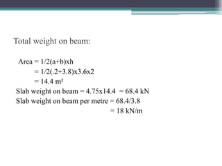
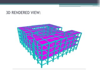
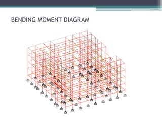
This document details the planning, analysis, and design of the academic block of a high school building. It includes the dimensions and specifications of the building components. Load calculations are performed to determine dead and live loads. The key structural elements - slab, beam, column, footing, and staircase - are designed based on the loading. Reinforcement details are provided for each element. The column with the maximum load of 1588.25 kN and beam with maximum bending moment of 166.526 kNm are identified. Manual calculations are included for design verification. The project helps gain knowledge of structural planning and design using software and code-based manual methods.


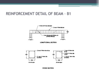
![Design of Beam - B1
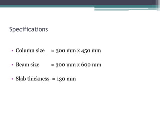
Size of the beam = 300mm * 600 mm
Clear cover = 25 mm
Moment = 166.526 kNm
Mu limit = 0.138 fck b d²
= 0.138x25x300x550² = 313.08 k Nm
Mu < Mu limit
Hence it is doubly reinforced beam
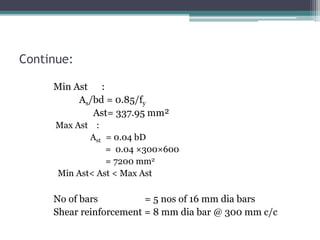
Main Reinforcement:
Ast =Mu = 0.87fyAst.d[1-(Ast.fy/bdfck)]
166.526x106 = (0.87x415xAstx550)
166.526x106 = 198577.5Ast-19.97
Ast = 924.55mm2 ≈ 925mm2](https://image.slidesharecdn.com/batch4ppt-240119082057-6efb099b/85/BATCH-4-PPT-pptx-29-320.jpg)