Download as PDF, PPTX

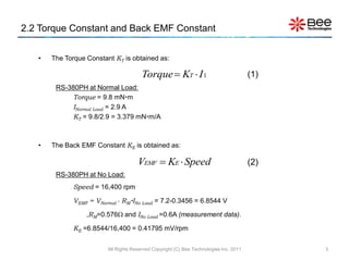
![2.7 Speed at No Load (Model)
Simulation
Speed at No Load
=16,400 rpm.
Normal Voltage
=7.2V.
Motor current
Time (s)
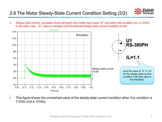
• This figure shows the simulated speed at no load (16,400rpm). To monitor the speed ,trace
“ I(U1.Vrpm) ” inside the model .SUBCKT.
Note: To show I(U1.Vrmp), select "Save Subcircuit Device Currents“ ( Tool > Control Panel > Save Default [tab] ).
All Rights Reserved Copyright (C) Bee Technologies Inc. 2011 7](https://image.slidesharecdn.com/29nov2011dcmtdrvltspice-111206002905-phpapp01/85/LTspice-DC-7-320.jpg)

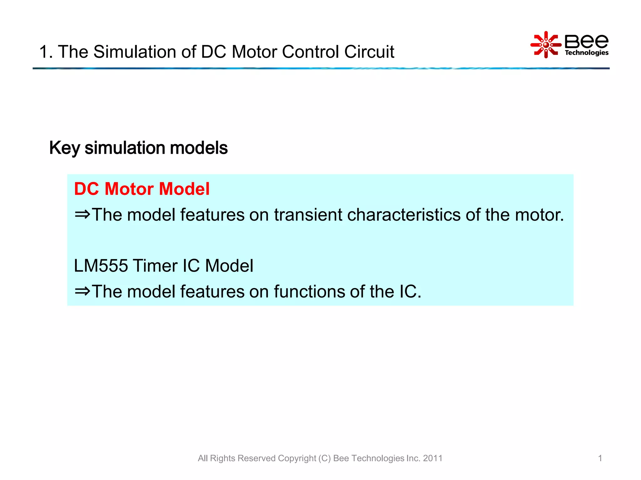
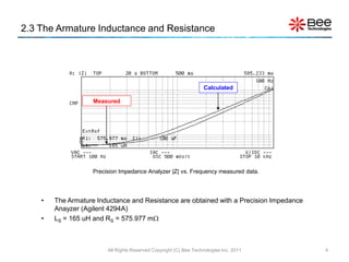
This document summarizes the simulation of a DC motor control circuit. It describes the DC motor and timer IC models used in the simulation. It then analyzes the specifications, parameters, and transient responses of a sample RS-380PH motor at no load and under different load conditions. The simulations are compared to measurement data to validate the motor model. Settings for simulating the motor voltage and current are also provided.


![[DL輪読会]Imagination-Augmented Agents for Deep Reinforcement Learning / Learnin...](https://cdn.slidesharecdn.com/ss_thumbnails/dlhacksshioya201707281-170728054152-thumbnail.jpg?width=640&height=640&fit=bounds)