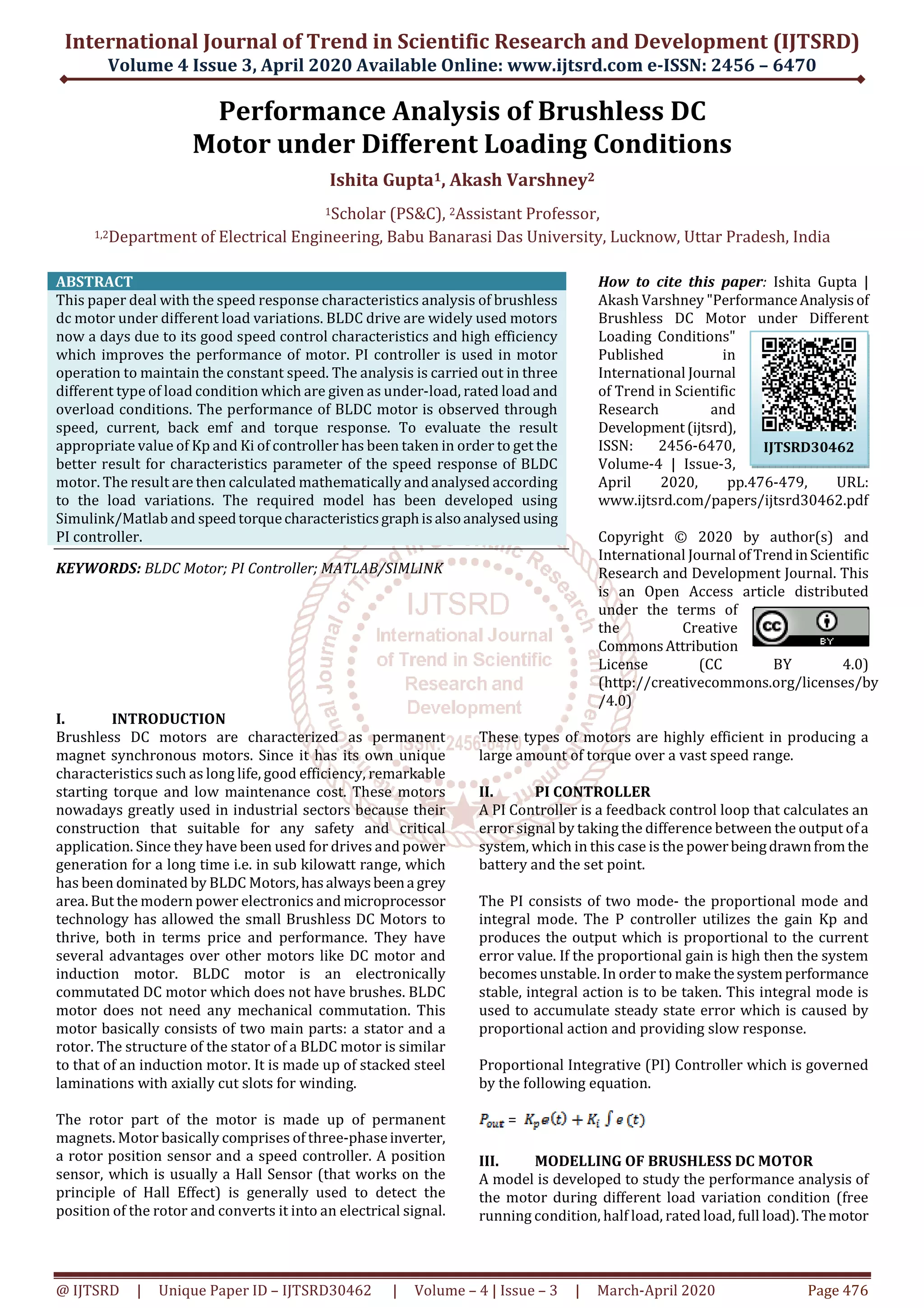
This paper analyzes the performance of brushless DC motors (BLDC) under various loading conditions using a PI controller to maintain constant speed. The study focuses on evaluating speed, current, torque, and back EMF responses during under-load, rated-load, and overload conditions, with simulation results indicating better performance in underloading scenarios. Key findings include specific performance metrics such as rise time, settling time, and maximum overshoot under different load conditions.
![International Journal of Trend in Scientific Research and Development (IJTSRD) @ www.ijtsrd.com eISSN: 2456-6470
@ IJTSRD | Unique Paper ID – IJTSRD30462 | Volume – 4 | Issue – 3 | March-April 2020 Page 478
Figure 5: Torque Response Curve
Figure 6: Current Response Curve
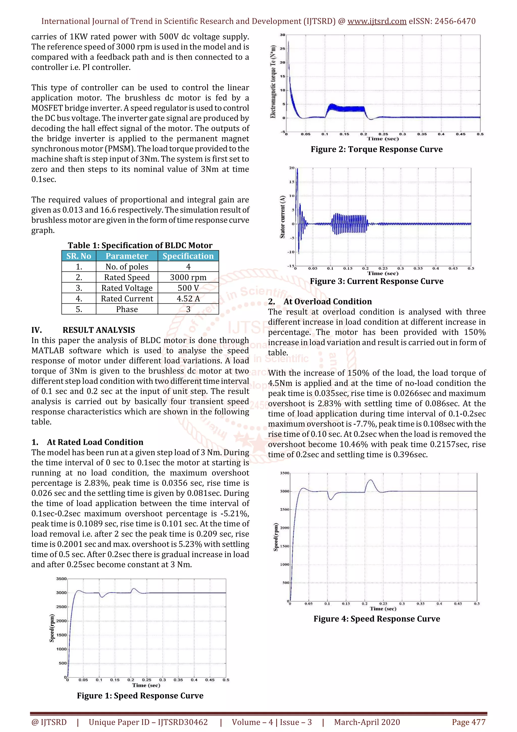
3. At Underload Condition
The result has been carried out with the decrease in load
variation at different decrease in percentage of 50% and
presented in the form of table. At 50% decrease of the
underload condition the load torque of 1.5Nm is applied. In
this the starting condition at no load between 0-0.1sec is
same as the overload condition when the motor is applied at
no-load. During the time interval of 0.1-0.2secwhentheload
is applied the overshoot percentage is -3.94%, rise time is
0.102sec and peak time is 0.1088sec with settling time of
0.155sec. At 0.2sec the overshoot is 3.94% with peak time of
0.2093sec, rise time is 0.201sec and settling time of
0.276sec.
Figure 7: Speed Response Curve
Figure 8: Torque Response Curve
Figure 9: Current Response Curve
Table 2: Time Response Characteristics at Different
Load Conditions
V. CONCLUSION
In order to achieve better time responseonBLDCmotor,a PI
controller has been modelled designed and performance
analysis is done in this work. The PI controller improves the
performance of BLDC motor drive. The simulation results
depict that BLDC motor show better performanceinthe case
of underloading condition as compared to rated loading
condition or overloading condition in terms of rise time,
delay time, settling time, peak time and overshoot.
REFERENCES
[1] Miss. Pragati K. Sharma, Prof. A. S. Sindekar
“Performance Analysis andComparisonofBLDCMotor
Drive using PI and FOC”, International Conference on
Global Trends in Signal Processing, Information
Computing and Communication 2016.](https://image.slidesharecdn.com/94performanceanalysisofbrushlessdcmotorunderdifferentloadingconditions-200531102354/75/Performance-Analysis-of-Brushless-DC-Motor-under-Different-Loading-Conditions-3-2048.jpg)
![International Journal of Trend in Scientific Research and Development (IJTSRD) @ www.ijtsrd.com eISSN: 2456-6470
@ IJTSRD | Unique Paper ID – IJTSRD30462 | Volume – 4 | Issue – 3 | March-April 2020 Page 479
[2] D. Gupta, “Speed Control of Brushless DC motor using
Fuzzy PID controller”, IEEE conference on Emerging
trends in Electrical, Electronics & Sustainable Energy
System, Volume: 2, pp 221-224, 11-12 March, 2016,
KNIT, India.
[3] Saiyad Mahammadsoaib M, Patel Sajid M, Vector
Controlled PMSM drive using SVPWM technique – A
MATLAB / Simulink Implementation, 2015 IEEE
[4] C. Sheeba Joice, P. Nivedhitha, “Simulation of speed
control of brushless dc motor with Fuzzy controlle”,
International Journal of Electrical,ElectronicsandData
Communication, ISSN: 2320-2084, Volume-2, Issue-4,
April-2014.
[5] Manoj Kushwah, Prof. Ashis Patra, “Tuning PID
controller for speed control of DC motor using soft
computing technique-AReview”,AdvanceinElectronic
and Electric Engineering,Volume4,Issue02,Aug2014.
[6] C. P. Sigh, S. S. Kulkarni, S. C. Rana, kapil Deo, “State
space based simulink modeling of BLDC motor and its
speed control using Fuzzy PID controller”,
International Journal of Advance in Engineering
Science and Technology, volume 02, Issue 03, June
2013.
[7] K. Venkateswarlu “Comparative study on DC motor
using various controllers”, Research Direction,Volume
1, Issue 6, Dec 2013.
[8] Madhusudan Singh, Archna Garg, Performance
Evaluation of BLDC Motor with Conventional PI and
Fuzzy Speed Controller, 2012 IEEE
[9] Zhao Yongjuan, Pan Yutitan, “The Design and
Simulation of Fuzzy PID controller”, International
Forum on Information Technology and Applications,
Kunming, China, Vol 1, pp 95-98, 16-18 July 2010.
[10] Malik Elbuluk, Changsheng LI, ʊSliding Mode Observer
for Wide-Speed Sensorless Control of PMSM Drives, ۅ
2003 IEEE](https://image.slidesharecdn.com/94performanceanalysisofbrushlessdcmotorunderdifferentloadingconditions-200531102354/75/Performance-Analysis-of-Brushless-DC-Motor-under-Different-Loading-Conditions-4-2048.jpg)


![[000007]](https://cdn.slidesharecdn.com/ss_thumbnails/000007-211028000533-thumbnail.jpg?width=640&height=640&fit=bounds)


