The Institute of Rural Research And Development (IRRAD)-Architecture case study
•
1 like•1,654 views

IRRAD-sustainable development, environmental goals,zero runoff from the site,daylight and ventilation, photovoltaic panels, minimize the ecological foot print and carbon dioxide emissions,shading device

Recommended
Recommended
More Related Content
What's hot
What's hot (20)
Similar to The Institute of Rural Research And Development (IRRAD)-Architecture case study
Similar to The Institute of Rural Research And Development (IRRAD)-Architecture case study (20)
More from Shailja km
More from Shailja km (12)
Recently uploaded
Recently uploaded (20)
The Institute of Rural Research And Development (IRRAD)-Architecture case study
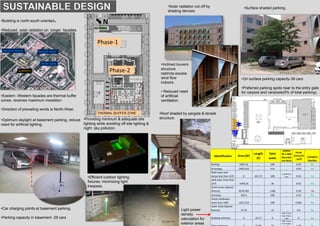
- 1. •Building is north-south oriented. •Reduced solar radiation on longer facades. •. SUNPATH Summer winds SUSTAINABLE DESIGN •Solar radiation cut-off by shading devices Phase-1 Phase-2 N •Eastern -Western facades are thermal buffer zones, receives maximum insolation. •Direction of prevailing winds is North-West. Winter winds Monsoon breeze THERMAL BUFFER ZONE •Inclined louvers structure restricts excess wind flow indoors. • Reduced need of artificial ventilation. •On surface parking capacity-39 cars •Preferred parking spots near to the entry gate for carpool and vanpools(5% of total parking). •Surface shaded parking. •Optimum daylight at basement parking, reduce need for artificial lighting. •Car charging points at basement parking. •Parking capacity in basement -29 cars Identification Area (SF) Length (F) Total watts ASHRAE 90.1.2004 Allowable LPD (W/F) Actual LPD (w/sf) , (w/f) Complies (Yes/No) Parking 5505.31 _ 108 _ 0.02 Yes Driveways 14013.43 _ 414 _ 0.03 Yes Walk ways land ramps less than 10 ft 0 422.72 108 1.0W/linear foot 0.26 Yes walk ways more than 10 ft 1466.26 _ 36 _ 0.02 Yes Green areas (Special feature) 6520.992 _ 1168 _ 0.18 No stairways 342.4 _ 108 _ 0.32 Yes ramps (walkways more than 10ft) 1322.514 _ 108 _ 0.082 Yes water body (Special feature) 37.45 _ 15 _ 0.4 Yes building entrance 0 10.17 0 20W / linear foot of door width 0 Yes 30W / linear foot of door •Providing minimum & adequate site lighting while avoiding off site lighting & night sky pollution. •Efficient outdoor lighting fixtures, minimizing light trespass. Light power density calculation for exterior areas •Roof shaded by pergola & tensile structure.
- 2. SUSTAINABLE DESIGN ROOF GARDEN OVER BASEMENT •Landscaping: A Micro climate has been setup by growing trees, roof garden & vegetation around the buildings. Heat absorbed by roof surface •Exterior Roof Assembly: From outside to inside, wall construction consists of 13mm Broken China Mosaic,65mm Brick, 50mm PUF (R-13), 9.5mm screed, waterproofing, and 203mm” concrete slab on the interior. •U-assembly = 0.064 Btu/h-ft2-F •Windows: The window-to-wall ratio of the proposed office building is 19.84%. Building Envelope •Exterior Wall Assembly: : From outside to inside, wall construction consists of 45 mm Stone cladding, 40 mm PUF {For South-East Wall(EWall3-C) 40 mm Cavity}, 230 mm brick 15 mm cement mortar. •U-assembly(For South -East) = 0.274 Btu/h-ft2-F •U-assembly(For all other sides ) = 0.079 Btu/h-ft2-F •Mud brick walls are not painted. CERAMIC TILES & JIRAWAL GRANITE • Roof treatment to reduce heat gains Type Glazing Window Properties Glazing- Double Clear Window (Assembly) U-value (in Btu/h.ft2.ºF) 0.33 Visible Light Transmittance 71% Solar Heat Gain Coefficient 0.51 Efficient interior lighting •High SRI materials used on roof surface. •The luminaires are suspended 600mm below the ceiling level. 35® NO LIGHT TRESSPASSES •In plan, where the luminaire is placed parallel to the window the maximum intensity beam is directed downwards at 30º (gamma) It can be seen that the maximum intensity luminous beam intersects the opaque surface and does not pass through the transparent or translucent surface; hence no light trespassing is caused. •The maximum candela value of all interior lighting falls within the building (not out through windows). Heat island effect on site Heat absorbed by paving Less radiation due to shading Heat absorbed by paving Heat reflected Heat reflected due to high SRI material
- 3. •Total HVAC energy cost savings of approximately 9% of total 47.3% savings. Air Handling Unit Hybrid approach of air conditioning Systems ENERGY Radiant slab •The Radiant Slab counters the Sensible Load and •The AHU counters the Latent Load. Controlling Parameters •Modulation of Mixing Valve installed on the common Header Radiant Header. •Controlling of Re-circulating for Radiant Cooling System. ) Radiant Slab System VAV System Water recirculation pump (for radiant slab) Chillers Upstream •Variable air volume (VAV) controlled fans were provided. •Restrooms are facilitated with an exhaust flow, and staircases are naturally ventilated Air Handling Unit The position and size of the space for air conditioning or air outlets has to be checked pipes near the manifold with a spacing of less than 15cm and pipes outside the chilled slab led in corrugated pipe Radiant slab This system consists of running chilled water pipes embedded in the ceiling slab. Sensible load cooling using radiant chilled water pipes in the slab operating at 15– 19°C differential chilled water temp & latent load using Air handling unit operating at 6.6 – 12.2°C differential chilled water temp. 6.6°C chilled water shall be produced by chiller and 15°C chilled water shall be produced by using Heat exchanger having input water at 6.6°C from the chiller. Controls Monitoring Parameters • Slab Temperature Monitoring. •Room Temperature Sensor. •Room Humidity Sensor. •Common Header Temperature in Radiant Piping system. Elements of fire fighting system •Hydrant & sprinkler pump •Jockey pump •Fire alarm& sensors •Hose reel •Diesel engine pump
- 4. Sound(db) level measurement COMFORT •Reduced level of noise indoors. CFM measurement •Maintained air flow circulation indoors. • No automobile or industrial pollution to the site. •IRRAD phase-2 – is a mechanically ventilated space. •High efficiency pre‐filters and bag filters are being provided in supply air stream of all AHU’s to remove any contaminants from outside air. location of co2 sensors •System for Co2 monitoring in phase II measure Co2 differential between indoor and outdoor Co2 concentrations for each zone. •30% increased ventilation Control measures to prevent indoor air quality problems during construction. 1. HVAC protection- properly covered up, remain free from dust & grime. 5. Scheduling- construction activities over the duration of the project minimize the impact on the indoor air quality. 2.Source-Low toxicity is maintained by using low VOC complaint materials. 3. Pathway- Temporary barriers used to isolates area of work of construction. 4.Housekeeping-electrical panels should be covered with water proofing covers to protect from water entry. •Construction workers are provided with helmets. •Low emitting materials used. •Roll out mats at the entryways minimize dirt and particulates from entering the building. Visual comfort-Daylighting Indoor air quality •Sufficient Daylighting in all spaces. Office/cabin Common room •Indoor plantation to improve air quality indoors.
- 5. WATER •Water efficient fixtures & fittings • 50% water efficiency in air conditioning system •Landscape which uses captured rain and recycled site water to eliminate portable water consumption for irrigation. Measures adopted to reduce waste and decrease the portable water demand •Use of low flush fixtures •Use of STP treated water for flushing Rain water harvesting system Rain water recharging pit Preserving site features: Measures followed before construction: •Top Soil Conservation •Wise disposal of excavated soil •Measures followed during construction: •Dust control measures •Barricading •Gravel pit was constructed •Preservation of existing vegetation •Site management plan •Measures followed post construction: •Growing vegetation • Rain water harvesting system (sedimentation basin) Gravel pit was constructed Top soil conservation Pebbles & grass pavers to minimize Storm water runoff. Preserving trees