- The document discusses the monostatic calibration of the TanDEM-X satellites TerraSAR-X and TanDEM-X.
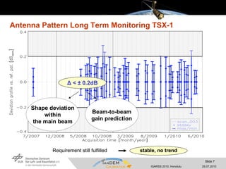
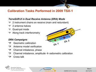
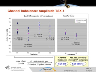
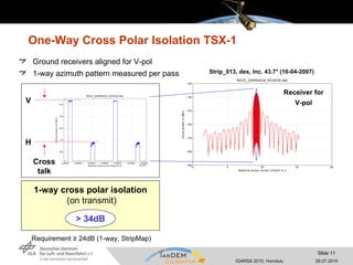
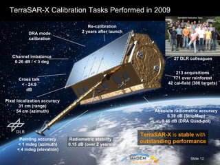
- Key calibration tasks performed on TerraSAR-X in 2009 included geometric calibration, antenna model verification, radiometric calibration, and channel imbalance measurements.
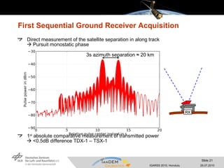
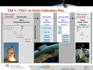
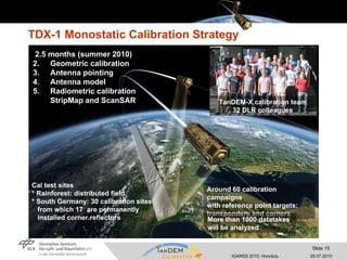
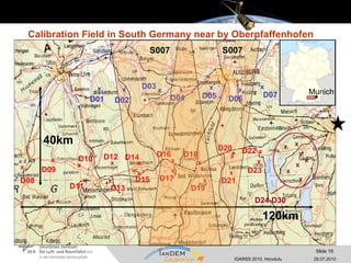
- TanDEM-X's monostatic calibration strategy in 2010 involved geometric calibration, antenna pointing determination, antenna model development, and radiometric calibration using test sites.
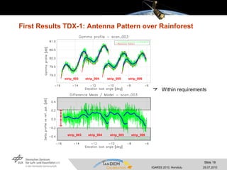
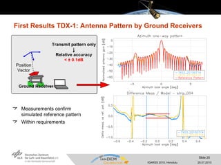
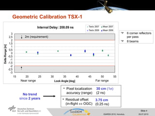
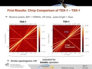
- Preliminary results showed the TanDEM-X transmit pulses were similar to TerraSAR-X, its thermal noise matched ground measurements, and antenna patterns agreed with models and each other to within requirements.
![Pointing Determination in Azimuth TSX-1 Updates Improved ground receiver position Re-adjustment between star trackers Improvements 2007 2009 Measurement accuracy ≤ 7.9 Hz ≤ 2.6 Hz (1 ) per pass < 1.0 mdeg < 0.33 mdeg Mean doppler 16 Hz 5.9 Hz Residual pointing error 2 mdeg 0.74 mdeg Notch patterns with different look angles 4 ground receivers per pass Near range Elevation look angle [degree] Far range Frequency shift due to mispointing [Hz]](https://image.slidesharecdn.com/th1-l10-3-100729131102-phpapp02/85/TH1-L10-3-MONOSTATIC-CALIBRATION-OF-BOTH-TANDEM-X-SATELLITES-5-320.jpg)
![Radiometric Calibration TSX-1 µ 2009 = -56.53dB + 0.10dB (CR) = -56.43dB µ ≤ ± 0.2dB within scene TerraSAR-X is extremely stable 0.15dB over 2 years µ ≤ ± 0.2dB within full performance range Requirement 0.5 dB (1 ) over 6 months ! CR: corner reflector 6 corner reflectors across the swath 3 beams (low, mid, high inc.) -57,6 -57,4 -57,2 -57 -56,8 -56,6 -56,4 -56,2 -56 -55,8 -55,6 10 15 20 25 30 35 40 45 Look Angle [deg] Abs Cal Factor [dB] strip_002 strip_007 strip_013 = -56.50 dB = 0.21 dB = -56.76 dB = 0.24 dB = -56.45 dB = 0.16 dB strip_007 -57,6 -57,4 -57,2 -57 -56,8 -56,6 -56,4 -56,2 -56 -55,8 -55,6 Abs Cal Factor [dB] near mid far = -56.73 dB = 0.22 dB = -56.65 dB = 0.17 dB = -56.62 dB = 0.18 dB = -56.67 dB = 0.18 dB Radiometric Stability Abs. Cal Factor 2007 - 56.58 dB 2009 - 56.43 dB ≤ ± 0.2dB Antenna Model](https://image.slidesharecdn.com/th1-l10-3-100729131102-phpapp02/85/TH1-L10-3-MONOSTATIC-CALIBRATION-OF-BOTH-TANDEM-X-SATELLITES-8-320.jpg)
![First results TDX-1: TRM Characterization – PN Gating blue: measured in flight cold red: measured in flight hot black: on ground characterization Receive Phase [degrees] Amplitude [dB] Transmit Phase [degrees] Amplitude [dB] Warm instrument stability](https://image.slidesharecdn.com/th1-l10-3-100729131102-phpapp02/85/TH1-L10-3-MONOSTATIC-CALIBRATION-OF-BOTH-TANDEM-X-SATELLITES-18-320.jpg)