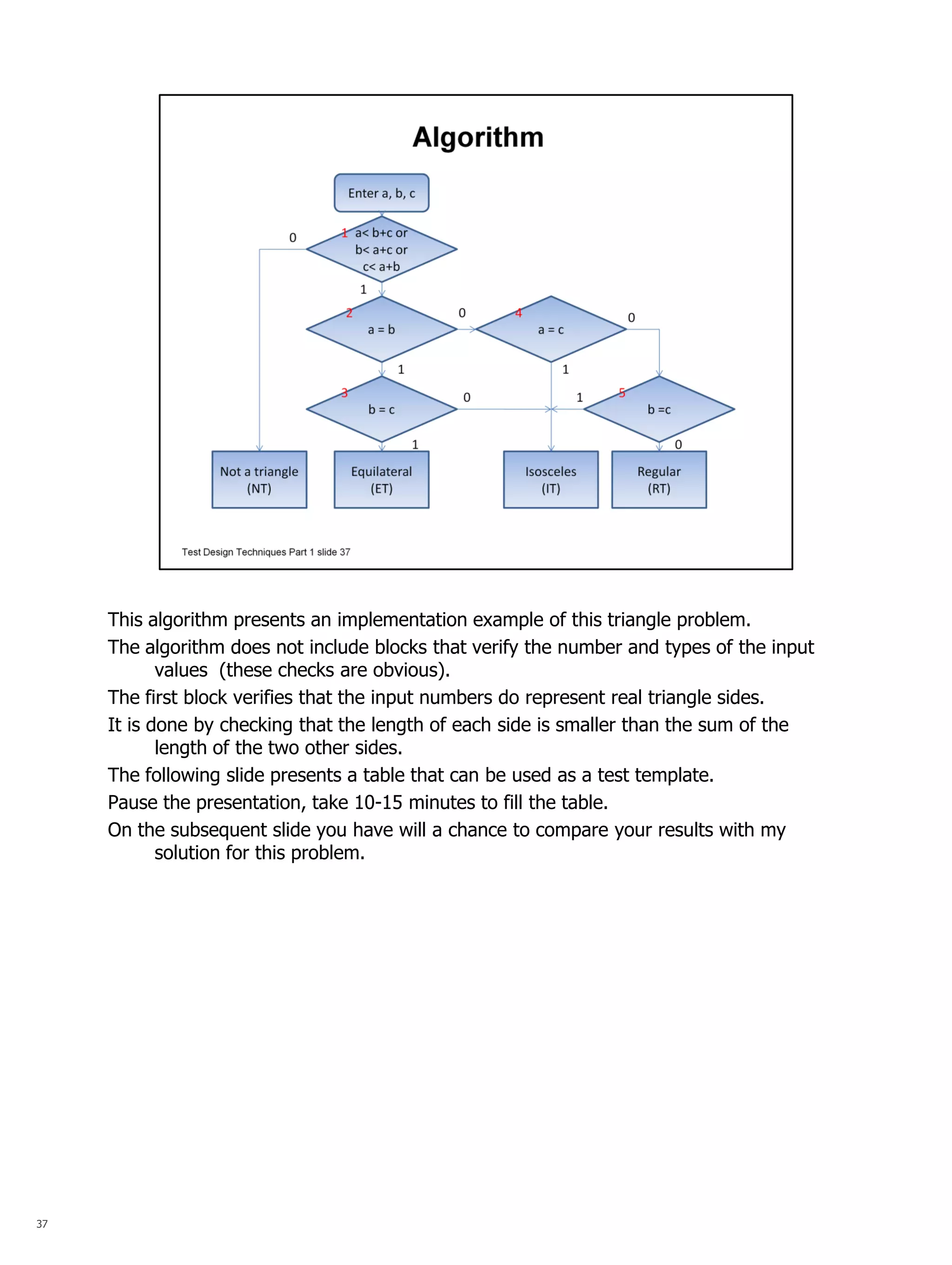
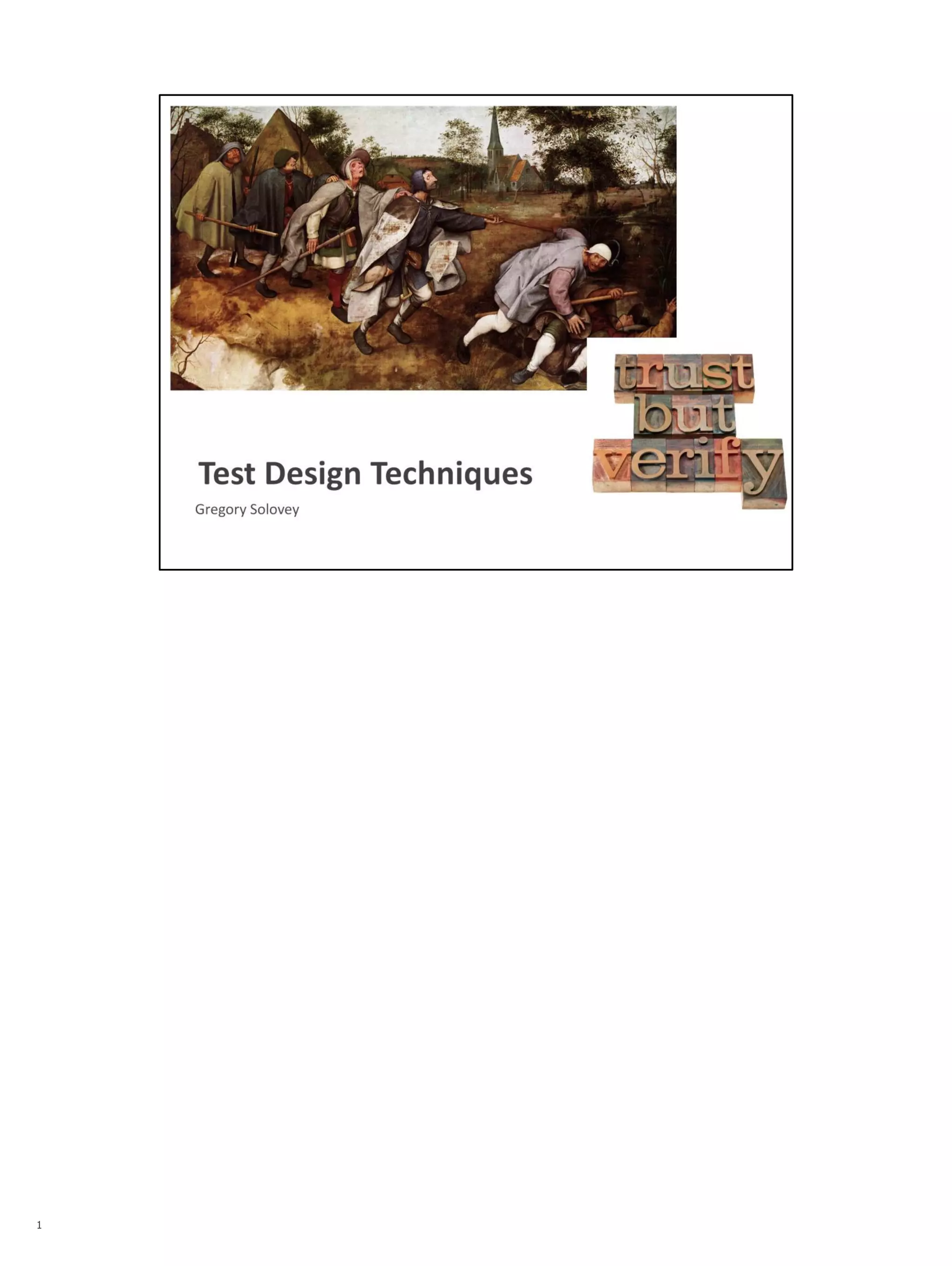
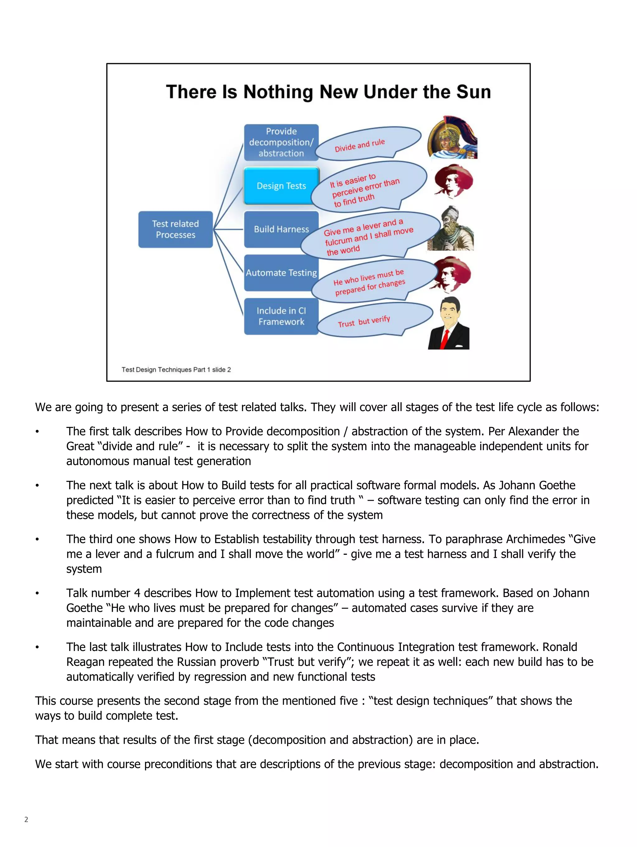
SlideShare a Scribd company logo
1
2 
We are going to present a series of test related talks. They will cover all stages of the test life cycle as follows: 
•The first talk describes How to Provide decomposition / abstraction of the system. Per Alexander the Great “divide and rule” - it is necessary to split the system into the manageable independent units for autonomous manual test generation 
•The next talk is about How to Build tests for all practical software formal models. As Johann Goethe predicted “It is easier to perceive error than to find truth “ – software testing can only find the error in these models, but cannot prove the correctness of the system 
•The third one shows How to Establish testability through test harness. To paraphrase Archimedes “Give me a lever and a fulcrum and I shall move the world” - give me a test harness and I shall verify the system 
•Talk number 4 describes How to Implement test automation using a test framework. Based on Johann Goethe “He who lives must be prepared for changes” – automated cases survive if they are maintainable and are prepared for the code changes 
•The last talk illustrates How to Include tests into the Continuous Integration test framework. Ronald Reagan repeated the Russian proverb “Trust but verify”; we repeat it as well: each new build has to be automatically verified by regression and new functional tests This course presents the second stage from the mentioned five : “test design techniques” that shows the ways to build complete test. That means that results of the first stage (decomposition and abstraction) are in place. We start with course preconditions that are descriptions of the previous stage: decomposition and abstraction.
3 
Typical software applications usually include millions lines of code. However, the test effort is not daunting, because it is not actually proportional with size of the software, but it is proportional to the size of independent modules. 
The good news is that modern software follows this paradigm by using a layered architecture, where lower layers provide services for the higher ones through APIs. For instance, an embedded system consists of the following layers: drivers, OS, middleware, applications. 
Furthermore, each layer comprises independent services and features. Each software release is described by a set of incremental requirements and architecture documents; before development starts, the requirements are refined to a sufficiently detailed level. 
This is usually where test planning and test generation start.
4 
When decomposition is done the object is presented with as a hierarchy of the system documentation 
Where: 
FRS – Functional Requirement Specification that is defined by customers 
Then 
FTS – Feature Technical Specification as and End2End or ARD – Architectural Requirements Document 
And finally 
SSD – System Specification Document as LLD – Low Level Design or SRD – System Requirement Document 
In Common view the test type is focused on a particular test objective. It is easy to give a definition ,for example, regression, functional, sanity , unit test. But it is challenging and there are no formal processes to extract from the functional test the regression test cases, or from the regression test the sanity cases. 
In our view, test types reflect only exiting documents. Then unit, functional, sanity tests reflect the respective document in their hierarchy from low level to higher one
5 
A requirement is usually written in business terms, which is not the best format for writing test cases, because there are no definitions of possible errors. Only subject matter experts can define tests, based on their expertise. Moreover, each tester will come up with their own unique set. Our goal is to provide an approach where each tester will end up with the same set of test cases for the one requirement.
6 
Examples of informal requirements that were taken from Internet as the test interview questions. Informal presentation of requirements made test design an art. Each tester ends up with different set of intuitive cases.
7 
When an abstraction is done each requirement is presented as a formal model. Formal models such as, for example, condition, algorithm, state machine, etc., use formal definitions of error classes and there are test design methods that guarantee the error coverage. 
A tester should ensure that each requirement is presented as a formal model prior to building tests. 
The goal is to transform tester’s test design skill from an art to the craft. The word ‘craft’ here is an opposite to the art, but not something that is primitive and not creative, but in the sense of being predictable and repeatable
8 
I would like to start the course with two epigraphs that, from my point of view, present the spirit and even the justification of the current course. 
Whenever James Whittaker asked about the completion of a Test Plan, he would always get the answer today or tomorrow. And this supports my view that using the formal test design techniques all tests can be built in days for a new product release, based on architecture and requirements documents. Hours - Days, but not months. 
Second saying belongs to Austin Schutz, the author of Expect Perl package. He took only a small percentage of the language Tcl, but delivers almost all functionality necessary for writing interactive scripts. I tried to present the similar approach: propose simplified versions of test design methods that are good enough to cover the majority of implementation errors: we use minimum theory of test design to cover most of the practical needs.
9 
Our approach to the test design is based on these two Dijkstra’s axioms. 
•To demonstrate object correctness in a convincing manner it must be usefully structured. “Usefully structured” reflects necessity to use only formal models in test design techniques. And an abstraction of the requirements guarantees the usefulness. 
•Testing shows the presence, not the absence of bugs. It means that the test design techniques should be oriented to errors coverage. 
Thus the formal model is not a purpose, but the means to identify the error that needs to be found
10 
Our experience shows that all requirements that we worked with can be describe with the following models: 
“Atomic” models: the arithmetic, relational and logical expressions 
“Compound” models: an algorithm, a state machine, an instruction set and a syntax. 
However, note, that object description can be hierarchical and recursive. Some object elements can be presented as a model itself and so on. 
I would like to repeat, that, in most cases, it is a tester’s job to present the business oriented requirements as set of formal models.
11 
Each formal model is represented by a set of elements, their attributes, connection between the elements, and element’s function. 
The general error model is ‘element-swap fault’, where one of the object’s element is inadvertently swapped with another element of the same type. For example: it can be a replacement of one variable for another, one connection for another, one functional symbol to another, etc. These errors will not be caught by syntax analyzer and have to be caught by respective test cases.
12 
All test design techniques that are presented in this course will be derived from these two methods: Boundary Value Analysis and Path Sensitization Technique 
The errors change the boundaries of the object. 
Boundary Value Analysis requires selection of test cases at the edges of the equivalence classes and the closest values around the edges. The boundary analysis provides a separation between correct and faulty models’ elements. 
Path Sensitization Technique requires choosing the path from the origin of the fault to the output and ensuring that the effect of the fault will be propagated to the output. The Path Sensitization Technique allows to see the error, which was identified by a boundary analysis, at the object output interface.
13 
Based on Primary Test Design Methods we will describe how to build test cases for arithmetic, relational and logical expressions (“atomic” models). We will then show how the two can be combined to create test design methods for “compound” models, such algorithm, state machine, instruction set and syntax. This picture is the content of our class.
14 
The following template is going to be used for each technique presentation: 
Object Model as a set of particular elements, the connections among them and their functions 
Error Model as the element distortions of the current model 
Test design technique as a procedure for building test cases that identify all errors of described types and a procedure for building the minimum set of test cases 
Example
15 
Arithmetic expression Model: 
•Numeric constants and variables are arithmetic expressions 
•If α and β are arithmetic expressions, then so are α + β, α / β, etc. Error Model: α  β, α  constant; ‘+’  ‘-’; etc Each fault creates an output different from output of the faultless object. The output of relational and logical expressions is binary. To distinguish the correct expected result from the faulty ones requires more than two cases. The arithmetic expressions, on other hand, return numerical (non-binary) values. This fact allow us to have the fewest number of test cases that can find all the errors. Our approach is to deliver the changes of each variable value to the expression output. This way we can prove that the developers did not replace the variable name with another name or with a constant. Test design technique includes 2 steps: 
•Use two test cases where each variable is substituted with two different values. 
•Add a test case for each division operator to verify that the ‘division by zero’ returns an error message.
16 
Let’s build a test for arithmetic expression ‘a + 45 / (b-c)’ 
Three cases are needed to verify the arithmetic expression. 
Note that the value for each variable changes in each of the three test cases. 
The third case also verifies the correct behavior for ‘division by 0’.
17 
Relational expression 
Model: 
If α and β are arithmetic expressions then α > β , α == β, α <= β, etc are relational expressions 
Error Model: α  β, α  constant; ‘==’  ‘<=’; etc 
Known methods for a relational expression are based on the branch coverage . They require that each predicate (‘<’, ‘<=’, =. etc) be true and false. However, this approach always leaves some uncovered faults. For example, to verify the expression a > 4 per known techniques two test cases should be chosen: 
a=3 (no) and a= 5 (yes) 
However, the fault “>”  “>=” will not be identified. 
Test design technique: 
Based on the boundary value analysis, three test cases are needed for each predicate symbol . The three test cases will use values on and around a boundary.
18 
Here are the three test cases for relational expression ‘a > 4’ 
The cases needed are a=3, a=4, a=5.
19 
Logical expression Model: 
•Logical constants and variables are logical expressions. 
•Relational expressions are logical expressions. 
•If α is a logical expression then so is !α (not α) 
•If α and β are logical expressions then so α ∧ β , α ∨ β. Error Model: α  β, α  constant; ‘∧’  ‘∨’; etc The known ATPG (Automatic Test Pattern Generation) methods can be used to test a logical expression. These methods have been developing for the last 50 years for use with combinational and sequential circuits. Early test generation algorithms were the Boolean difference and D- algorithm. Note that the size of circuits grows from hundreds gates (AND – OR elements) to hundreds of millions. Each new method dealt with exponential increase of circuits sizes. These methods need to be practical in terms of memory requirements and reduction of computation time. However, our case is different: we need to have a method to build test cases manually for the logical expression with a size less than 10 variables. In my opinion, the Victor Danilov’s Graph model and the respective method greatly simplifies the creation of a manual test.
20 
Graph Model: 
•Remove all global logical negations using de Morgan’s Law: (!(a & b) ≡!a || !b and !(a || b)≡!a & !b) 
•Present each input variable by an edge. 
•Beginning from most embedded parenthesis: 
•present each OR operator by a parallel connection of edges; 
•present each AND operator by a sequential connection of edges;
21 
Let’s take for example a logical expression F = ((b or c) and d). 
First of all variables are presented in the graph as edges 
‘b or c’ is presented with parallel edges. 
(sub-graph ‘b or c’ and edge ‘d’) is presented by a sequential connection. 
If a Boolean variable is ‘TRUE’ then the edge stays in the graph, if it is FALSE, then the respective edge is removed from the graph. 
If after removing all edges that are equal to ‘FALSE’ a pathway from SP (start point) to the EP (end point) still exists, then the logical expression is ‘TRUE’. 
For example if all variables are ‘TRUE’ then a connection between SP and EP exist and F =“TRUE’ as well 
if all variables are ‘FALSE’ then the is no a connection between SP and EP and F =“FALSE’ as well
22 
The previous slide illustrates how to calculate the result value of logical expression. It was done by removing edges that have the ‘FALSE’ value and observing the presence of the path way from the SP to the EP. If a pathway exist that ‘F’ is equal to ‘TRUE’, otherwise to ‘FALSE’. 
Now we understand that a graph is adequately presents a logical expression. 
Before presenting a test design method we need to introduce two definitions: 
Let’s call the path the set of Boolean variables that, being equal to ‘TRUE’, form a pathway from SP to EP. For instance, the path ‘cd’ means that c=1 and d=1. Another path is ‘bd’: b=1 and d=1; these paths make the expression F= ’TRUE’. 
Let’s call the cut the set of Boolean variables that being equal to ‘FALSE’ does not allow presence of any paths. The presence of the cut makes the logical expression F equal to ‘FALSE’. For example, the cut ‘cb’ means c=0 and b=0. Another cut ‘d’: d=0.
23 
It is time to describe the test design technique for the logical expressions: The method is based on the application that automatically builds test cases using the Graph model. I wrote this application 40 years ago, when the graph model was introduced. The method creates the minimum number of test cases that covers all single faults. Here is a simplified version of this approach: 
•Build graph paths from the SP to the EP that cover all edges. Each “path” becomes a test case when all edges that are not on the path (parallel edges) are cut (assign ‘FALSE’ value). 
•Build graph cuts that cover all edges. Each “cut” becomes a test case when all edges that do not belong to the cut are assigned the value ‘TRUE’.
24
25
26
27 
This slide presents the test cases to verify our logical expression Only seven test cases are needed to find all possible errors of this logical expression, whereas if we used all permutations of seven Boolean variables then 128 cases would be necessary (which is 2 in power of 7). Note: 
•The path is not only a connection between SP and EP. It is the only connection – all parallel connections are cut. Therefore all ‘stack-in-0’ faults (variable is replaced with constant ‘FALSE’) will be visible for the edges that belong to the path. If an error occur (one of the variable on the path will have value ‘FAUSE’ instead of ‘TRUE’) then output function will be set to ‘FALSE’ instead of ‘TRUE’ (real value would be different from the expected one) 
•The cut is the only separation between SP and EP. The rest of the edges (variable) are set to ‘TRUE’. Therefore each ‘stuck-in-1’ faults (variable is replaced with constant ‘TRUE’) will de identified for each edge (variable) that belongs to the cut.
28 
Note that nested relationships can exist - some functional blocks can be algorithms themselves.
29 
The existing structural approaches to test design (statement, branch, path coverage) do not guarantee the coverage of all possible implementation errors (see an example for a relational expression a>4 above at slide 18) The proposed test design method includes two stages for each functional and conditional block: 
•Design test cases for each expression 
•Use the Path Sensitization Technique to propagate the results to the output
30
31 
The conditional block contains three relational expressions 
‘A>5’, ‘B>0’, ‘B<9’ that are encapsulated into a logical expression. 
Let’s name them X, Y, Z: 
X  A>5 
Y B>0 
Z B<9 
The logical expression X OR (Y AND Z) can be represented by the graph model. 
First we build test cases for the logical expression and then extend the test with cases that verifies the relational expressions
32
33 
Based on the Path Sensitization Technique we will use the logical expression test to propagate the relational and arithmetical expression results to the output of the algorithm. 
Thus, 
path 1 makes the output depend on the value of X and therefore allows us to verify the relational expression ‘A>5’; 
path 2 makes the output depend on the values of Y and Z and therefore allows us to verify the relational expression ‘B>0’ and ‘B<9’. 
Let’s expand table 4 based on these facts: 
Each relational expression requires three test cases: 
X  A>5 needs test cases A= 4; A=5; A= 6 
Y B>0 needs test cases B=-1; B=0; B= 1 
Z B<9 needs test cases B= 8; B=9; B=10 
To test the arithmetic expression (D/A) three test cases are needed: 
(D=6; A=A1); (D=8; A=A2); (D=6; A=0), where A1 <> A2. 
Let’s incorporate expression cases into the logical expression cases.
34 
Let’s take a look at the table. 
The first path’s output depends on the variable X. Since variable X presents the relational expression the first set of 3 test cases in the table are created to verify it. 
The second path’s output depends on the variables Y and Z. The second set of 3 test cases in the table are created to verify the relational expression B>0 and the third set of 3 cases verifies respectively B<9. 
Through this exercise we notice that all cuts are already implemented: 
The cut 1 is represented by test cases #4 or #5 
The cut 2 is represented by test cases #8 or #9 respectively. 
The test cases #3 and #6 can be selected as the test set for an arithmetic expression ‘D/A’. We need two values for ‘D’: let them be ‘8’ and ‘6’. 
We add the test case #10 verifies the ’division by 0’ case. 
For all other cases any value for variable ‘D’ can be selected, for instance ‘6’. 
The final set of test cases is presented on the following slide.
35
36 
These are informal requirements. We will present them with an algorithm model.
37 
This algorithm presents an implementation example of this triangle problem. 
The algorithm does not include blocks that verify the number and types of the input values (these checks are obvious). 
The first block verifies that the input numbers do represent real triangle sides. 
It is done by checking that the length of each side is smaller than the sum of the length of the two other sides. 
The following slide presents a table that can be used as a test template. 
Pause the presentation, take 10-15 minutes to fill the table. 
On the subsequent slide you have will a chance to compare your results with my solution for this problem.
38
39 
We proposed 35 test cases for the triangle test. Search online to see other solutions and compare with ours. 
The presentation of the algorithm test design technique would not be complete if the algorithm’s loops were not mentioned. Our example does not include loops. In our approach, however, the tests for a logical expression that controls the number of loop iterations, based on the boundary conditions, would require the loop execution of none, one, max, max+1 times, exactly as a traditional test design method for algorithms would require.
40 
A State Machine model is represented by a set of states and a set of input conditions that transfer control between states and generate respective outputs. 
Error Model: connection errors; transfer and output function errors 
Assumption: 
Each state is observable. For a state machine without observability, it is a challenge to identify the arrival state based on the series of outputs. However, a developer can easily implement a ‘show’ function that will publish the object’s state, therefore it is realistic to assume that the state can be made observable.
41 
The Test Design Method for the state machine is similar to the algorithm one: 
•Implement the Path Sensitization Technique for each state and for each transfer between states. 
•For each transfer function use a test design method for the logical conditions. 
•For each output function use a test design method for the respective output model (check all output messages formats).
42 
Our example presents the simplified states for a TCP transaction. Various events define transitions between states. 
In our proposed solution each test starts from the initial state #1. 
Yet in most cases, the subsequent test cases can be run from the state where the previous test case finished. 
However, to increase the error resolution it is preferable to make all test cases independent from each other and run them from the initial state. 
Independence allows us to continue testing after finding an error, without skipping some test cases.
43 
In this example we assume that some kind of ‘show’ function exists to report the arrival state. 
The first three test cases check the condition ‘A and B’, the following two cases verify the condition ‘C or D’, and so on. 
In general, the output functions are more sophisticated than a simple state report. 
Report format options are: printouts, transactions, mails, etc. The boundary analyses can be used to test various output reports.
44 
Instruction set 
An Instruction set model is a collection of commands, with each command represented by a name, input and output parameters, and a model that describes how output results are derived from the input parameters. 
Examples are PDP-11 or IBM instruction sets. Another example is a messaging system instruction set: ‘create buffer’, ‘fill buffer’, ‘send a message’, etc. 
Assumption: Each command is testable, meaning that it can be initiated from an external interface and its results can be observed on the external interface. However, if commands or APIs are not accessible from an external interface (in the case of embedded system, for example), then developers can create a test harness that provides access to all commands and APIs.
45 
Test Design Method: 
•Use the Path Sensitization Technique for each command to create a “macro- instruction” as a set of commands that allow us to set all command parameters and retrieve the results of their execution. 
•Use the boundary analysis for each input parameter and output response. 
•Use the respective test design method for the command’s functions. The next slide presents an example that is an instruction set for a messaging service.
46 
Based on the path sensitization technique, for each command, let’s build the “macro- instruction” as a set of commands that allow us to set all command parameters and retrieve the results of their execution.
47 
All necessary “macro-instruction” are presented in the following table. 
We will not build test cases since we already discussed the boundary analyses technique application.
48 
The last model we are going to discuss is a Syntax Model: 
Syntax is a set of rules that describe the various elements of objects and how they form a correct structure. Each rule is often based on the definition of a preceding rules.
49 
The natural order of the syntax rules defines the test hierarchy. Test Design Method: 
•Start the test design from the first rule and continue based on the rule order. 
•Use the Boundary value analysis for all the rule’s elements. 
•Use the test techniques for the various rule’s expressions.
50 
Example: A fragment of the syntax of a XML file that describes the test results in UC/ TC hierarchy
51 
This XML file describes the test results in the UC/TC hierarchy
52 
The table presents a fragment of the test where the content of the first column refers to the respective rule. In this test plan the word “processed” can be read “can be shown on the GUI of the web site of the test results”. The first rule is “…The ‘ucSet’ element contains one or more Non-Empty Closed Elements ‘uc’…” The key word here is “one or more”. The boundary analyses requires us to use three test cases (lines 1,2,3) for none, one and two ‘uc’ as a content of a Test Set. And the conclusions are: 
•A Path Sensitization technique can be applied using the natural order of the rules. 
•A Boundary analysis is applied to the content of each rule.
53 
Remember that this picture presented the content of our class. Based on two primary Test Design Methods (A Path Sensitization technique and A Boundary analysis) we described how to build test cases for arithmetic, relational and logical expressions (“atomic” models) and then show how the two can be combined to create test design methods for “compound” models, such algorithm, state machine, instruction set and syntax.
54 
The necessary condition for a test design is to guarantee the coverage of all implementation errors. 
However, sometimes there are more requests than can be applied to the test. 
If we do not expect errors, for example, when we run a regression test over and over again, we prefer to run a minimum set of cases to save time of execution. 
On other hand, when we deal with new code the goal is to identify each and every error separately to save debugging time. 
The latter goal (highest error resolution) is different from the one to get the smallest test set to run. 
This is shown on the graphs. 
Each regression test case is built to cover as many errors as possible. 
Each ‘new feature’ test case is build to cover as few errors as possible. 
The desired result is to have a one-to-one relationship between a test case and each fault. 
However some errors produces the same output and are indistinguishable. 
They form a class of equivalent errors. The next slide presents the approach used to build these two test types.
55 
Let’s build two types of tests for the algorithm that calculates first ‘A’ as a disjunction of ‘B’ and ‘C’ and then calculate ‘F’ as a conjunction of ‘A’ and ‘D’. 
To build a regression test use the graph model described earlier that allows us to define a test as two paths and two cuts. 
To build the test of the second type ‘error identification test’, let’s first build the error tree, where all errors are ordered based on a ‘masking’ relationship. 
It means that error f1 masks (doesn't allow us to see) all other errors. 
The class of equivalent errors ‘a1, b1, c1’ covers errors ‘c0’ and ‘b0’, etc.
56 
Then we build test cases for each class of equivalent errors. 
We do not discuss here the formal method to build the error tree and design identifiers for each class. 
We are just presenting the result. 
The number of test cases is bigger in the second set, but the error resolution is bigger as well.

More Related Content

What's hot

Testing Fundamentals
Testing FundamentalsTesting Fundamentals
Testing Fundamentals
Kiran Kumar
 
Software Testing Techniques
Software Testing TechniquesSoftware Testing Techniques
Software Testing Techniques
Kiran Kumar
 
Input Space Partitioning
Input Space PartitioningInput Space Partitioning
Input Space PartitioningRiyad Parvez
 
Equivalence partinioning and boundary value analysis
Equivalence partinioning and boundary value analysisEquivalence partinioning and boundary value analysis
Equivalence partinioning and boundary value analysis
niharika5412
 
Test design techniques
Test design techniquesTest design techniques
Test design techniquesPragya Rastogi
 
Software Testing Techniques
Software Testing TechniquesSoftware Testing Techniques
Software Testing Techniques
Kiran Kumar
 
Black box testing
Black box testingBlack box testing
Black box testing
Abdul Basit
 
Software Quality Testing
Software Quality TestingSoftware Quality Testing
Software Quality Testing
Kiran Kumar
 
Dynamic analysis in Software Testing
Dynamic analysis in Software TestingDynamic analysis in Software Testing
Dynamic analysis in Software Testing
Sagar Pednekar
 
Black box testing or behavioral testing
Black box testing or behavioral testingBlack box testing or behavioral testing
Black box testing or behavioral testingSlideshare
 
Istqb ctfl-series - Black Box Testing
Istqb ctfl-series - Black Box TestingIstqb ctfl-series - Black Box Testing
Istqb ctfl-series - Black Box Testing
Disha Srivastava
 
10 software testing_technique
10 software testing_technique10 software testing_technique
10 software testing_technique
University of Computer Science and Technology
 
5 black box and grey box testing
5   black box and grey box testing5   black box and grey box testing
5 black box and grey box testing
Yisal Khan
 
Whitepaper Test Case Design and Testing Techniques- Factors to Consider
Whitepaper Test Case Design and Testing Techniques- Factors to ConsiderWhitepaper Test Case Design and Testing Techniques- Factors to Consider
Whitepaper Test Case Design and Testing Techniques- Factors to Consider
RapidValue
 
Black box testing
Black box testingBlack box testing
Black box testing
Nakul Sharma
 
Test Case Design and Technique
Test Case Design and TechniqueTest Case Design and Technique
Test Case Design and Technique
Sachin-QA
 
Black Box Testing Techniques by Sampath M
Black Box Testing Techniques by Sampath MBlack Box Testing Techniques by Sampath M
Black Box Testing Techniques by Sampath M
Forziatech
 
Blackbox
BlackboxBlackbox
Blackbox
GuruKrishnaTeja
 

What's hot (20)

Testing Fundamentals
Testing FundamentalsTesting Fundamentals
Testing Fundamentals
 
Software Testing Techniques
Software Testing TechniquesSoftware Testing Techniques
Software Testing Techniques
 
Testing techniques
Testing techniquesTesting techniques
Testing techniques
 
Input Space Partitioning
Input Space PartitioningInput Space Partitioning
Input Space Partitioning
 
Test design techniques
Test design techniquesTest design techniques
Test design techniques
 
Equivalence partinioning and boundary value analysis
Equivalence partinioning and boundary value analysisEquivalence partinioning and boundary value analysis
Equivalence partinioning and boundary value analysis
 
Test design techniques
Test design techniquesTest design techniques
Test design techniques
 
Software Testing Techniques
Software Testing TechniquesSoftware Testing Techniques
Software Testing Techniques
 
Black box testing
Black box testingBlack box testing
Black box testing
 
Software Quality Testing
Software Quality TestingSoftware Quality Testing
Software Quality Testing
 
Dynamic analysis in Software Testing
Dynamic analysis in Software TestingDynamic analysis in Software Testing
Dynamic analysis in Software Testing
 
Black box testing or behavioral testing
Black box testing or behavioral testingBlack box testing or behavioral testing
Black box testing or behavioral testing
 
Istqb ctfl-series - Black Box Testing
Istqb ctfl-series - Black Box TestingIstqb ctfl-series - Black Box Testing
Istqb ctfl-series - Black Box Testing
 
10 software testing_technique
10 software testing_technique10 software testing_technique
10 software testing_technique
 
5 black box and grey box testing
5   black box and grey box testing5   black box and grey box testing
5 black box and grey box testing
 
Whitepaper Test Case Design and Testing Techniques- Factors to Consider
Whitepaper Test Case Design and Testing Techniques- Factors to ConsiderWhitepaper Test Case Design and Testing Techniques- Factors to Consider
Whitepaper Test Case Design and Testing Techniques- Factors to Consider
 
Black box testing
Black box testingBlack box testing
Black box testing
 
Test Case Design and Technique
Test Case Design and TechniqueTest Case Design and Technique
Test Case Design and Technique
 
Black Box Testing Techniques by Sampath M
Black Box Testing Techniques by Sampath MBlack Box Testing Techniques by Sampath M
Black Box Testing Techniques by Sampath M
 
Blackbox
BlackboxBlackbox
Blackbox
 

Viewers also liked

Decision table
Decision tableDecision table
Decision table
jeebala
 
Designing tests mtcp2008
Designing tests mtcp2008Designing tests mtcp2008
Designing tests mtcp2008
Shawky Allam
 
Designing Classroom Tests: 6 Critical Questions
Designing Classroom Tests: 6 Critical QuestionsDesigning Classroom Tests: 6 Critical Questions
Designing Classroom Tests: 6 Critical Questions
Eddy White, Ph.D.
 
Test Case Design
Test Case DesignTest Case Design
Test Case Designacatalin
 
ISTQB foundation level - day 2
ISTQB foundation level - day 2ISTQB foundation level - day 2
ISTQB foundation level - day 2
Shuchi Singla AKT,SPC4,PMI-ACP,ITIL(F),CP-AAT
 
Test specifications and designs
Test specifications and designs  Test specifications and designs
Test specifications and designs
ahfameri
 
Chapter 8 software testing
Chapter 8 software testingChapter 8 software testing
Chapter 8 software testing
despicable me
 
Test plan
Test planTest plan
Test plan
Nadia Nahar
 
Istqb foundation level day 1
Istqb foundation level   day 1Istqb foundation level   day 1
Istqb foundation level day 1
Shuchi Singla AKT,SPC4,PMI-ACP,ITIL(F),CP-AAT
 
Guidelines and Practical Approaches for Test Construction Cindy Cruz-Cabrera...
Guidelines and Practical Approaches for Test Construction  Cindy Cruz-Cabrera...Guidelines and Practical Approaches for Test Construction  Cindy Cruz-Cabrera...
Guidelines and Practical Approaches for Test Construction Cindy Cruz-Cabrera...
University of the Philippines Diliman
 
Principles and Techniques of Test Construction
Principles and Techniques of Test ConstructionPrinciples and Techniques of Test Construction
Principles and Techniques of Test Construction
Olufemi Jeremiah Olubodun
 
stages of test construction
stages of test constructionstages of test construction
stages of test construction
irshad narejo
 
Principles of Test Construction 1
Principles of Test Construction 1Principles of Test Construction 1
Principles of Test Construction 1
Monica P
 
Test construction 2
Test construction 2Test construction 2
Test construction 2Arnel Rivera
 
Test construction 1
Test construction 1Test construction 1
Test construction 1Arnel Rivera
 
E-R DIAGRAMS, DFD'S AND STATE TRANSITION DIAGRAMS !!
E-R DIAGRAMS, DFD'S AND STATE TRANSITION DIAGRAMS !!E-R DIAGRAMS, DFD'S AND STATE TRANSITION DIAGRAMS !!
E-R DIAGRAMS, DFD'S AND STATE TRANSITION DIAGRAMS !!
Nidhi Kakani
 

Viewers also liked (19)

Decision table
Decision tableDecision table
Decision table
 
Designing tests mtcp2008
Designing tests mtcp2008Designing tests mtcp2008
Designing tests mtcp2008
 
Designing Classroom Tests: 6 Critical Questions
Designing Classroom Tests: 6 Critical QuestionsDesigning Classroom Tests: 6 Critical Questions
Designing Classroom Tests: 6 Critical Questions
 
Test Case Design
Test Case DesignTest Case Design
Test Case Design
 
ISTQB foundation level - day 2
ISTQB foundation level - day 2ISTQB foundation level - day 2
ISTQB foundation level - day 2
 
Test plan
Test planTest plan
Test plan
 
Test specifications and designs
Test specifications and designs  Test specifications and designs
Test specifications and designs
 
Chapter 8 software testing
Chapter 8 software testingChapter 8 software testing
Chapter 8 software testing
 
Test plan
Test planTest plan
Test plan
 
Istqb foundation level day 1
Istqb foundation level   day 1Istqb foundation level   day 1
Istqb foundation level day 1
 
Guidelines and Practical Approaches for Test Construction Cindy Cruz-Cabrera...
Guidelines and Practical Approaches for Test Construction  Cindy Cruz-Cabrera...Guidelines and Practical Approaches for Test Construction  Cindy Cruz-Cabrera...
Guidelines and Practical Approaches for Test Construction Cindy Cruz-Cabrera...
 
Principles and Techniques of Test Construction
Principles and Techniques of Test ConstructionPrinciples and Techniques of Test Construction
Principles and Techniques of Test Construction
 
stages of test construction
stages of test constructionstages of test construction
stages of test construction
 
Test construction
Test constructionTest construction
Test construction
 
Principles of Test Construction 1
Principles of Test Construction 1Principles of Test Construction 1
Principles of Test Construction 1
 
Test construction 2
Test construction 2Test construction 2
Test construction 2
 
Test construction 1
Test construction 1Test construction 1
Test construction 1
 
E-R DIAGRAMS, DFD'S AND STATE TRANSITION DIAGRAMS !!
E-R DIAGRAMS, DFD'S AND STATE TRANSITION DIAGRAMS !!E-R DIAGRAMS, DFD'S AND STATE TRANSITION DIAGRAMS !!
E-R DIAGRAMS, DFD'S AND STATE TRANSITION DIAGRAMS !!
 
Test design techniques
Test design techniquesTest design techniques
Test design techniques
 

Similar to Test design techniques

Model Driven Testing: requirements, models & test
Model Driven Testing: requirements, models & test Model Driven Testing: requirements, models & test
Model Driven Testing: requirements, models & test
Gregory Solovey
 
Chapter 8 Testing Tactics.ppt Software engineering
Chapter 8 Testing Tactics.ppt Software engineeringChapter 8 Testing Tactics.ppt Software engineering
Chapter 8 Testing Tactics.ppt Software engineering
AnasHassan52
 
Chapter 8 Testing Tactics.ppt
Chapter 8 Testing Tactics.pptChapter 8 Testing Tactics.ppt
Chapter 8 Testing Tactics.ppt
VijayaPratapReddyM
 
Types of Software Testing
Types of Software TestingTypes of Software Testing
Types of Software TestingNishant Worah
 
Generating Test Cases
Generating Test CasesGenerating Test Cases
Generating Test Cases
VivekRajawat9
 
Chapter 10 Testing and Quality Assurance1Unders.docx
Chapter 10 Testing and Quality Assurance1Unders.docxChapter 10 Testing and Quality Assurance1Unders.docx
Chapter 10 Testing and Quality Assurance1Unders.docx
keturahhazelhurst
 
Software testing for biginners
Software testing for biginnersSoftware testing for biginners
Software testing for biginners
Sriman Eshwar
 
Testing 2 - Thinking Like A Tester
Testing 2 - Thinking Like A TesterTesting 2 - Thinking Like A Tester
Testing 2 - Thinking Like A Tester
ArleneAndrews2
 
Driven to Tests
Driven to TestsDriven to Tests
Driven to Tests
Kevlin Henney
 
Testing Experience - Evolution of Test Automation Frameworks
Testing Experience - Evolution of Test Automation FrameworksTesting Experience - Evolution of Test Automation Frameworks
Testing Experience - Evolution of Test Automation Frameworks
Łukasz Morawski
 
Annotated Bibliography .Guidelines Annotated Bibliograph.docx
Annotated Bibliography  .Guidelines Annotated Bibliograph.docxAnnotated Bibliography  .Guidelines Annotated Bibliograph.docx
Annotated Bibliography .Guidelines Annotated Bibliograph.docx
justine1simpson78276
 
Different Methodologies For Testing Web Application Testing
Different Methodologies For Testing Web Application TestingDifferent Methodologies For Testing Web Application Testing
Different Methodologies For Testing Web Application Testing
Rachel Davis
 
A PRACTITIONER'S GUIDE TO SOFTWARE TEST DESIGN [Summary]
A PRACTITIONER'S GUIDE TO SOFTWARE TEST DESIGN [Summary]A PRACTITIONER'S GUIDE TO SOFTWARE TEST DESIGN [Summary]
A PRACTITIONER'S GUIDE TO SOFTWARE TEST DESIGN [Summary]
Khizra Sammad
 
Software testing introduction
Software testing introductionSoftware testing introduction
Software testing introduction
Sriman Eshwar
 
Assessing Unit Test Quality
Assessing Unit Test QualityAssessing Unit Test Quality
Assessing Unit Test Qualityguest268ee8
 
Assignment 1 Week 2.docx1Assignment 1 Topic Selection.docx
Assignment 1 Week 2.docx1Assignment 1 Topic Selection.docxAssignment 1 Week 2.docx1Assignment 1 Topic Selection.docx
Assignment 1 Week 2.docx1Assignment 1 Topic Selection.docx
sherni1
 
Role+Of+Testing+In+Sdlc
Role+Of+Testing+In+SdlcRole+Of+Testing+In+Sdlc
Role+Of+Testing+In+Sdlc
mahendra singh
 

Similar to Test design techniques (20)

Model Driven Testing: requirements, models & test
Model Driven Testing: requirements, models & test Model Driven Testing: requirements, models & test
Model Driven Testing: requirements, models & test
 
Chapter 8 Testing Tactics.ppt Software engineering
Chapter 8 Testing Tactics.ppt Software engineeringChapter 8 Testing Tactics.ppt Software engineering
Chapter 8 Testing Tactics.ppt Software engineering
 
Chapter 8 Testing Tactics.ppt
Chapter 8 Testing Tactics.pptChapter 8 Testing Tactics.ppt
Chapter 8 Testing Tactics.ppt
 
Types of Software Testing
Types of Software TestingTypes of Software Testing
Types of Software Testing
 
Generating Test Cases
Generating Test CasesGenerating Test Cases
Generating Test Cases
 
Chapter 10 Testing and Quality Assurance1Unders.docx
Chapter 10 Testing and Quality Assurance1Unders.docxChapter 10 Testing and Quality Assurance1Unders.docx
Chapter 10 Testing and Quality Assurance1Unders.docx
 
Software testing for biginners
Software testing for biginnersSoftware testing for biginners
Software testing for biginners
 
Testing 2 - Thinking Like A Tester
Testing 2 - Thinking Like A TesterTesting 2 - Thinking Like A Tester
Testing 2 - Thinking Like A Tester
 
Testing
TestingTesting
Testing
 
Driven to Tests
Driven to TestsDriven to Tests
Driven to Tests
 
Testing Experience - Evolution of Test Automation Frameworks
Testing Experience - Evolution of Test Automation FrameworksTesting Experience - Evolution of Test Automation Frameworks
Testing Experience - Evolution of Test Automation Frameworks
 
50120140502017
5012014050201750120140502017
50120140502017
 
Annotated Bibliography .Guidelines Annotated Bibliograph.docx
Annotated Bibliography  .Guidelines Annotated Bibliograph.docxAnnotated Bibliography  .Guidelines Annotated Bibliograph.docx
Annotated Bibliography .Guidelines Annotated Bibliograph.docx
 
Testing
TestingTesting
Testing
 
Different Methodologies For Testing Web Application Testing
Different Methodologies For Testing Web Application TestingDifferent Methodologies For Testing Web Application Testing
Different Methodologies For Testing Web Application Testing
 
A PRACTITIONER'S GUIDE TO SOFTWARE TEST DESIGN [Summary]
A PRACTITIONER'S GUIDE TO SOFTWARE TEST DESIGN [Summary]A PRACTITIONER'S GUIDE TO SOFTWARE TEST DESIGN [Summary]
A PRACTITIONER'S GUIDE TO SOFTWARE TEST DESIGN [Summary]
 
Software testing introduction
Software testing introductionSoftware testing introduction
Software testing introduction
 
Assessing Unit Test Quality
Assessing Unit Test QualityAssessing Unit Test Quality
Assessing Unit Test Quality
 
Assignment 1 Week 2.docx1Assignment 1 Topic Selection.docx
Assignment 1 Week 2.docx1Assignment 1 Topic Selection.docxAssignment 1 Week 2.docx1Assignment 1 Topic Selection.docx
Assignment 1 Week 2.docx1Assignment 1 Topic Selection.docx
 
Role+Of+Testing+In+Sdlc
Role+Of+Testing+In+SdlcRole+Of+Testing+In+Sdlc
Role+Of+Testing+In+Sdlc
 

Recently uploaded

A Sighting of filterA in Typelevel Rite of Passage
A Sighting of filterA in Typelevel Rite of PassageA Sighting of filterA in Typelevel Rite of Passage
A Sighting of filterA in Typelevel Rite of Passage
Philip Schwarz
 
In 2015, I used to write extensions for Joomla, WordPress, phpBB3, etc and I ...
In 2015, I used to write extensions for Joomla, WordPress, phpBB3, etc and I ...In 2015, I used to write extensions for Joomla, WordPress, phpBB3, etc and I ...
In 2015, I used to write extensions for Joomla, WordPress, phpBB3, etc and I ...
Juraj Vysvader
 
Large Language Models and the End of Programming
Large Language Models and the End of ProgrammingLarge Language Models and the End of Programming
Large Language Models and the End of Programming
Matt Welsh
 
Custom Healthcare Software for Managing Chronic Conditions and Remote Patient...
Custom Healthcare Software for Managing Chronic Conditions and Remote Patient...Custom Healthcare Software for Managing Chronic Conditions and Remote Patient...
Custom Healthcare Software for Managing Chronic Conditions and Remote Patient...
Mind IT Systems
 
Field Employee Tracking System| MiTrack App| Best Employee Tracking Solution|...
Field Employee Tracking System| MiTrack App| Best Employee Tracking Solution|...Field Employee Tracking System| MiTrack App| Best Employee Tracking Solution|...
Field Employee Tracking System| MiTrack App| Best Employee Tracking Solution|...
informapgpstrackings
 
Gamify Your Mind; The Secret Sauce to Delivering Success, Continuously Improv...
Gamify Your Mind; The Secret Sauce to Delivering Success, Continuously Improv...Gamify Your Mind; The Secret Sauce to Delivering Success, Continuously Improv...
Gamify Your Mind; The Secret Sauce to Delivering Success, Continuously Improv...
Shahin Sheidaei
 
Text-Summarization-of-Breaking-News-Using-Fine-tuning-BART-Model.pptx
Text-Summarization-of-Breaking-News-Using-Fine-tuning-BART-Model.pptxText-Summarization-of-Breaking-News-Using-Fine-tuning-BART-Model.pptx
Text-Summarization-of-Breaking-News-Using-Fine-tuning-BART-Model.pptx
ShamsuddeenMuhammadA
 
GlobusWorld 2024 Opening Keynote session
GlobusWorld 2024 Opening Keynote sessionGlobusWorld 2024 Opening Keynote session
GlobusWorld 2024 Opening Keynote session
Globus
 
Enhancing Research Orchestration Capabilities at ORNL.pdf
Enhancing Research Orchestration Capabilities at ORNL.pdfEnhancing Research Orchestration Capabilities at ORNL.pdf
Enhancing Research Orchestration Capabilities at ORNL.pdf
Globus
 
First Steps with Globus Compute Multi-User Endpoints
First Steps with Globus Compute Multi-User EndpointsFirst Steps with Globus Compute Multi-User Endpoints
First Steps with Globus Compute Multi-User Endpoints
Globus
 
Launch Your Streaming Platforms in Minutes
Launch Your Streaming Platforms in MinutesLaunch Your Streaming Platforms in Minutes
Launch Your Streaming Platforms in Minutes
Roshan Dwivedi
 
Globus Compute Introduction - GlobusWorld 2024
Globus Compute Introduction - GlobusWorld 2024Globus Compute Introduction - GlobusWorld 2024
Globus Compute Introduction - GlobusWorld 2024
Globus
 
Webinar: Salesforce Document Management 2.0 - Smarter, Faster, Better
Webinar: Salesforce Document Management 2.0 - Smarter, Faster, BetterWebinar: Salesforce Document Management 2.0 - Smarter, Faster, Better
Webinar: Salesforce Document Management 2.0 - Smarter, Faster, Better
XfilesPro
 
Beyond Event Sourcing - Embracing CRUD for Wix Platform - Java.IL
Beyond Event Sourcing - Embracing CRUD for Wix Platform - Java.ILBeyond Event Sourcing - Embracing CRUD for Wix Platform - Java.IL
Beyond Event Sourcing - Embracing CRUD for Wix Platform - Java.IL
Natan Silnitsky
 
Innovating Inference - Remote Triggering of Large Language Models on HPC Clus...
Innovating Inference - Remote Triggering of Large Language Models on HPC Clus...Innovating Inference - Remote Triggering of Large Language Models on HPC Clus...
Innovating Inference - Remote Triggering of Large Language Models on HPC Clus...
Globus
 
Climate Science Flows: Enabling Petabyte-Scale Climate Analysis with the Eart...
Climate Science Flows: Enabling Petabyte-Scale Climate Analysis with the Eart...Climate Science Flows: Enabling Petabyte-Scale Climate Analysis with the Eart...
Climate Science Flows: Enabling Petabyte-Scale Climate Analysis with the Eart...
Globus
 
Understanding Globus Data Transfers with NetSage
Understanding Globus Data Transfers with NetSageUnderstanding Globus Data Transfers with NetSage
Understanding Globus Data Transfers with NetSage
Globus
 
GraphSummit Paris - The art of the possible with Graph Technology
GraphSummit Paris - The art of the possible with Graph TechnologyGraphSummit Paris - The art of the possible with Graph Technology
GraphSummit Paris - The art of the possible with Graph Technology
Neo4j
 
Exploring Innovations in Data Repository Solutions - Insights from the U.S. G...
Exploring Innovations in Data Repository Solutions - Insights from the U.S. G...Exploring Innovations in Data Repository Solutions - Insights from the U.S. G...
Exploring Innovations in Data Repository Solutions - Insights from the U.S. G...
Globus
 
Globus Compute wth IRI Workflows - GlobusWorld 2024
Globus Compute wth IRI Workflows - GlobusWorld 2024Globus Compute wth IRI Workflows - GlobusWorld 2024
Globus Compute wth IRI Workflows - GlobusWorld 2024
Globus
 

Recently uploaded (20)

A Sighting of filterA in Typelevel Rite of Passage
A Sighting of filterA in Typelevel Rite of PassageA Sighting of filterA in Typelevel Rite of Passage
A Sighting of filterA in Typelevel Rite of Passage
 
In 2015, I used to write extensions for Joomla, WordPress, phpBB3, etc and I ...
In 2015, I used to write extensions for Joomla, WordPress, phpBB3, etc and I ...In 2015, I used to write extensions for Joomla, WordPress, phpBB3, etc and I ...
In 2015, I used to write extensions for Joomla, WordPress, phpBB3, etc and I ...
 
Large Language Models and the End of Programming
Large Language Models and the End of ProgrammingLarge Language Models and the End of Programming
Large Language Models and the End of Programming
 
Custom Healthcare Software for Managing Chronic Conditions and Remote Patient...
Custom Healthcare Software for Managing Chronic Conditions and Remote Patient...Custom Healthcare Software for Managing Chronic Conditions and Remote Patient...
Custom Healthcare Software for Managing Chronic Conditions and Remote Patient...
 
Field Employee Tracking System| MiTrack App| Best Employee Tracking Solution|...
Field Employee Tracking System| MiTrack App| Best Employee Tracking Solution|...Field Employee Tracking System| MiTrack App| Best Employee Tracking Solution|...
Field Employee Tracking System| MiTrack App| Best Employee Tracking Solution|...
 
Gamify Your Mind; The Secret Sauce to Delivering Success, Continuously Improv...
Gamify Your Mind; The Secret Sauce to Delivering Success, Continuously Improv...Gamify Your Mind; The Secret Sauce to Delivering Success, Continuously Improv...
Gamify Your Mind; The Secret Sauce to Delivering Success, Continuously Improv...
 
Text-Summarization-of-Breaking-News-Using-Fine-tuning-BART-Model.pptx
Text-Summarization-of-Breaking-News-Using-Fine-tuning-BART-Model.pptxText-Summarization-of-Breaking-News-Using-Fine-tuning-BART-Model.pptx
Text-Summarization-of-Breaking-News-Using-Fine-tuning-BART-Model.pptx
 
GlobusWorld 2024 Opening Keynote session
GlobusWorld 2024 Opening Keynote sessionGlobusWorld 2024 Opening Keynote session
GlobusWorld 2024 Opening Keynote session
 
Enhancing Research Orchestration Capabilities at ORNL.pdf
Enhancing Research Orchestration Capabilities at ORNL.pdfEnhancing Research Orchestration Capabilities at ORNL.pdf
Enhancing Research Orchestration Capabilities at ORNL.pdf
 
First Steps with Globus Compute Multi-User Endpoints
First Steps with Globus Compute Multi-User EndpointsFirst Steps with Globus Compute Multi-User Endpoints
First Steps with Globus Compute Multi-User Endpoints
 
Launch Your Streaming Platforms in Minutes
Launch Your Streaming Platforms in MinutesLaunch Your Streaming Platforms in Minutes
Launch Your Streaming Platforms in Minutes
 
Globus Compute Introduction - GlobusWorld 2024
Globus Compute Introduction - GlobusWorld 2024Globus Compute Introduction - GlobusWorld 2024
Globus Compute Introduction - GlobusWorld 2024
 
Webinar: Salesforce Document Management 2.0 - Smarter, Faster, Better
Webinar: Salesforce Document Management 2.0 - Smarter, Faster, BetterWebinar: Salesforce Document Management 2.0 - Smarter, Faster, Better
Webinar: Salesforce Document Management 2.0 - Smarter, Faster, Better
 
Beyond Event Sourcing - Embracing CRUD for Wix Platform - Java.IL
Beyond Event Sourcing - Embracing CRUD for Wix Platform - Java.ILBeyond Event Sourcing - Embracing CRUD for Wix Platform - Java.IL
Beyond Event Sourcing - Embracing CRUD for Wix Platform - Java.IL
 
Innovating Inference - Remote Triggering of Large Language Models on HPC Clus...
Innovating Inference - Remote Triggering of Large Language Models on HPC Clus...Innovating Inference - Remote Triggering of Large Language Models on HPC Clus...
Innovating Inference - Remote Triggering of Large Language Models on HPC Clus...
 
Climate Science Flows: Enabling Petabyte-Scale Climate Analysis with the Eart...
Climate Science Flows: Enabling Petabyte-Scale Climate Analysis with the Eart...Climate Science Flows: Enabling Petabyte-Scale Climate Analysis with the Eart...
Climate Science Flows: Enabling Petabyte-Scale Climate Analysis with the Eart...
 
Understanding Globus Data Transfers with NetSage
Understanding Globus Data Transfers with NetSageUnderstanding Globus Data Transfers with NetSage
Understanding Globus Data Transfers with NetSage
 
GraphSummit Paris - The art of the possible with Graph Technology
GraphSummit Paris - The art of the possible with Graph TechnologyGraphSummit Paris - The art of the possible with Graph Technology
GraphSummit Paris - The art of the possible with Graph Technology
 
Exploring Innovations in Data Repository Solutions - Insights from the U.S. G...
Exploring Innovations in Data Repository Solutions - Insights from the U.S. G...Exploring Innovations in Data Repository Solutions - Insights from the U.S. G...
Exploring Innovations in Data Repository Solutions - Insights from the U.S. G...
 
Globus Compute wth IRI Workflows - GlobusWorld 2024
Globus Compute wth IRI Workflows - GlobusWorld 2024Globus Compute wth IRI Workflows - GlobusWorld 2024
Globus Compute wth IRI Workflows - GlobusWorld 2024
 

Test design techniques

  • 1. 1
  • 2. 2 We are going to present a series of test related talks. They will cover all stages of the test life cycle as follows: •The first talk describes How to Provide decomposition / abstraction of the system. Per Alexander the Great “divide and rule” - it is necessary to split the system into the manageable independent units for autonomous manual test generation •The next talk is about How to Build tests for all practical software formal models. As Johann Goethe predicted “It is easier to perceive error than to find truth “ – software testing can only find the error in these models, but cannot prove the correctness of the system •The third one shows How to Establish testability through test harness. To paraphrase Archimedes “Give me a lever and a fulcrum and I shall move the world” - give me a test harness and I shall verify the system •Talk number 4 describes How to Implement test automation using a test framework. Based on Johann Goethe “He who lives must be prepared for changes” – automated cases survive if they are maintainable and are prepared for the code changes •The last talk illustrates How to Include tests into the Continuous Integration test framework. Ronald Reagan repeated the Russian proverb “Trust but verify”; we repeat it as well: each new build has to be automatically verified by regression and new functional tests This course presents the second stage from the mentioned five : “test design techniques” that shows the ways to build complete test. That means that results of the first stage (decomposition and abstraction) are in place. We start with course preconditions that are descriptions of the previous stage: decomposition and abstraction.
  • 3. 3 Typical software applications usually include millions lines of code. However, the test effort is not daunting, because it is not actually proportional with size of the software, but it is proportional to the size of independent modules. The good news is that modern software follows this paradigm by using a layered architecture, where lower layers provide services for the higher ones through APIs. For instance, an embedded system consists of the following layers: drivers, OS, middleware, applications. Furthermore, each layer comprises independent services and features. Each software release is described by a set of incremental requirements and architecture documents; before development starts, the requirements are refined to a sufficiently detailed level. This is usually where test planning and test generation start.
  • 4. 4 When decomposition is done the object is presented with as a hierarchy of the system documentation Where: FRS – Functional Requirement Specification that is defined by customers Then FTS – Feature Technical Specification as and End2End or ARD – Architectural Requirements Document And finally SSD – System Specification Document as LLD – Low Level Design or SRD – System Requirement Document In Common view the test type is focused on a particular test objective. It is easy to give a definition ,for example, regression, functional, sanity , unit test. But it is challenging and there are no formal processes to extract from the functional test the regression test cases, or from the regression test the sanity cases. In our view, test types reflect only exiting documents. Then unit, functional, sanity tests reflect the respective document in their hierarchy from low level to higher one
  • 5. 5 A requirement is usually written in business terms, which is not the best format for writing test cases, because there are no definitions of possible errors. Only subject matter experts can define tests, based on their expertise. Moreover, each tester will come up with their own unique set. Our goal is to provide an approach where each tester will end up with the same set of test cases for the one requirement.
  • 6. 6 Examples of informal requirements that were taken from Internet as the test interview questions. Informal presentation of requirements made test design an art. Each tester ends up with different set of intuitive cases.
  • 7. 7 When an abstraction is done each requirement is presented as a formal model. Formal models such as, for example, condition, algorithm, state machine, etc., use formal definitions of error classes and there are test design methods that guarantee the error coverage. A tester should ensure that each requirement is presented as a formal model prior to building tests. A tester should ensure that each requirement is presented as a formal model prior to building tests. The goal is to transform tester’s test design skill from an art to the craft. The word ‘craft’ here is an opposite to the art, but not something that is primitive and not creative, but in the sense of being predictable and repeatable
  • 8. 8 I would like to start the course with two epigraphs that, from my point of view, present the spirit and even the justification of the current course. Whenever James Whittaker asked about the completion of a Test Plan, he would always get the answer today or tomorrow. And this supports my view that using the formal test design techniques all tests can be built in days for a new product release, based on architecture and requirements documents. Hours - Days, but not months. Second saying belongs to Austin Schutz, the author of Expect Perl package. He took only a small percentage of the language Tcl, but delivers almost all functionality necessary for writing interactive scripts. I tried to present the similar approach: propose simplified versions of test design methods that are good enough to cover the majority of implementation errors: we use minimum theory of test design to cover most of the practical needs.
  • 9. 9 Our approach to the test design is based on these two Dijkstra’s axioms. •To demonstrate object correctness in a convincing manner it must be usefully structured. “Usefully structured” reflects necessity to use only formal models in test design techniques. And an abstraction of the requirements guarantees the usefulness. •Testing shows the presence, not the absence of bugs. It means that the test design techniques should be oriented to errors coverage. Thus the formal model is not a purpose, but the means to identify the error that needs to be found
  • 10. 10 Our experience shows that all requirements that we worked with can be describe with the following models: “Atomic” models: the arithmetic, relational and logical expressions “Compound” models: an algorithm, a state machine, an instruction set and a syntax. However, note, that object description can be hierarchical and recursive. Some object elements can be presented as a model itself and so on. I would like to repeat, that, in most cases, it is a tester’s job to present the business oriented requirements as set of formal models.
  • 11. 11 Each formal model is represented by a set of elements, their attributes, connection between the elements, and element’s function. The general error model is ‘element-swap fault’, where one of the object’s element is inadvertently swapped with another element of the same type. For example: it can be a replacement of one variable for another, one connection for another, one functional symbol to another, etc. These errors will not be caught by syntax analyzer and have to be caught by respective test cases.
  • 12. 12 All test design techniques that are presented in this course will be derived from these two methods: Boundary Value Analysis and Path Sensitization Technique The errors change the boundaries of the object. Boundary Value Analysis requires selection of test cases at the edges of the equivalence classes and the closest values around the edges. The boundary analysis provides a separation between correct and faulty models’ elements. Path Sensitization Technique requires choosing the path from the origin of the fault to the output and ensuring that the effect of the fault will be propagated to the output. The Path Sensitization Technique allows to see the error, which was identified by a boundary analysis, at the object output interface.
  • 13. 13 Based on Primary Test Design Methods we will describe how to build test cases for arithmetic, relational and logical expressions (“atomic” models). We will then show how the two can be combined to create test design methods for “compound” models, such algorithm, state machine, instruction set and syntax. This picture is the content of our class.
  • 14. 14 The following template is going to be used for each technique presentation: Object Model as a set of particular elements, the connections among them and their functions Error Model as the element distortions of the current model Test design technique as a procedure for building test cases that identify all errors of described types and a procedure for building the minimum set of test cases Example
  • 15. 15 Arithmetic expression Model: •Numeric constants and variables are arithmetic expressions •If α and β are arithmetic expressions, then so are α + β, α / β, etc. Error Model: α  β, α  constant; ‘+’  ‘-’; etc Each fault creates an output different from output of the faultless object. The output of relational and logical expressions is binary. To distinguish the correct expected result from the faulty ones requires more than two cases. The arithmetic expressions, on other hand, return numerical (non-binary) values. This fact allow us to have the fewest number of test cases that can find all the errors. Our approach is to deliver the changes of each variable value to the expression output. This way we can prove that the developers did not replace the variable name with another name or with a constant. Test design technique includes 2 steps: •Use two test cases where each variable is substituted with two different values. •Add a test case for each division operator to verify that the ‘division by zero’ returns an error message.
  • 16. 16 Let’s build a test for arithmetic expression ‘a + 45 / (b-c)’ Three cases are needed to verify the arithmetic expression. Note that the value for each variable changes in each of the three test cases. The third case also verifies the correct behavior for ‘division by 0’.
  • 17. 17 Relational expression Model: If α and β are arithmetic expressions then α > β , α == β, α <= β, etc are relational expressions Error Model: α  β, α  constant; ‘==’  ‘<=’; etc Known methods for a relational expression are based on the branch coverage . They require that each predicate (‘<’, ‘<=’, =. etc) be true and false. However, this approach always leaves some uncovered faults. For example, to verify the expression a > 4 per known techniques two test cases should be chosen: a=3 (no) and a= 5 (yes) However, the fault “>”  “>=” will not be identified. Test design technique: Based on the boundary value analysis, three test cases are needed for each predicate symbol . The three test cases will use values on and around a boundary.
  • 18. 18 Here are the three test cases for relational expression ‘a > 4’ The cases needed are a=3, a=4, a=5.
  • 19. 19 Logical expression Model: •Logical constants and variables are logical expressions. •Relational expressions are logical expressions. •If α is a logical expression then so is !α (not α) •If α and β are logical expressions then so α ∧ β , α ∨ β. Error Model: α  β, α  constant; ‘∧’  ‘∨’; etc The known ATPG (Automatic Test Pattern Generation) methods can be used to test a logical expression. These methods have been developing for the last 50 years for use with combinational and sequential circuits. Early test generation algorithms were the Boolean difference and D- algorithm. Note that the size of circuits grows from hundreds gates (AND – OR elements) to hundreds of millions. Each new method dealt with exponential increase of circuits sizes. These methods need to be practical in terms of memory requirements and reduction of computation time. However, our case is different: we need to have a method to build test cases manually for the logical expression with a size less than 10 variables. In my opinion, the Victor Danilov’s Graph model and the respective method greatly simplifies the creation of a manual test.
  • 20. 20 Graph Model: •Remove all global logical negations using de Morgan’s Law: (!(a & b) ≡!a || !b and !(a || b)≡!a & !b) •Present each input variable by an edge. •Beginning from most embedded parenthesis: •present each OR operator by a parallel connection of edges; •present each AND operator by a sequential connection of edges;
  • 21. 21 Let’s take for example a logical expression F = ((b or c) and d). First of all variables are presented in the graph as edges ‘b or c’ is presented with parallel edges. (sub-graph ‘b or c’ and edge ‘d’) is presented by a sequential connection. If a Boolean variable is ‘TRUE’ then the edge stays in the graph, if it is FALSE, then the respective edge is removed from the graph. If after removing all edges that are equal to ‘FALSE’ a pathway from SP (start point) to the EP (end point) still exists, then the logical expression is ‘TRUE’. For example if all variables are ‘TRUE’ then a connection between SP and EP exist and F =“TRUE’ as well if all variables are ‘FALSE’ then the is no a connection between SP and EP and F =“FALSE’ as well
  • 22. 22 The previous slide illustrates how to calculate the result value of logical expression. It was done by removing edges that have the ‘FALSE’ value and observing the presence of the path way from the SP to the EP. If a pathway exist that ‘F’ is equal to ‘TRUE’, otherwise to ‘FALSE’. Now we understand that a graph is adequately presents a logical expression. Before presenting a test design method we need to introduce two definitions: Let’s call the path the set of Boolean variables that, being equal to ‘TRUE’, form a pathway from SP to EP. For instance, the path ‘cd’ means that c=1 and d=1. Another path is ‘bd’: b=1 and d=1; these paths make the expression F= ’TRUE’. Let’s call the cut the set of Boolean variables that being equal to ‘FALSE’ does not allow presence of any paths. The presence of the cut makes the logical expression F equal to ‘FALSE’. For example, the cut ‘cb’ means c=0 and b=0. Another cut ‘d’: d=0.
  • 23. 23 It is time to describe the test design technique for the logical expressions: The method is based on the application that automatically builds test cases using the Graph model. I wrote this application 40 years ago, when the graph model was introduced. The method creates the minimum number of test cases that covers all single faults. Here is a simplified version of this approach: •Build graph paths from the SP to the EP that cover all edges. Each “path” becomes a test case when all edges that are not on the path (parallel edges) are cut (assign ‘FALSE’ value). •Build graph cuts that cover all edges. Each “cut” becomes a test case when all edges that do not belong to the cut are assigned the value ‘TRUE’.
  • 24. 24
  • 25. 25
  • 26. 26
  • 27. 27 This slide presents the test cases to verify our logical expression Only seven test cases are needed to find all possible errors of this logical expression, whereas if we used all permutations of seven Boolean variables then 128 cases would be necessary (which is 2 in power of 7). Note: •The path is not only a connection between SP and EP. It is the only connection – all parallel connections are cut. Therefore all ‘stack-in-0’ faults (variable is replaced with constant ‘FALSE’) will be visible for the edges that belong to the path. If an error occur (one of the variable on the path will have value ‘FAUSE’ instead of ‘TRUE’) then output function will be set to ‘FALSE’ instead of ‘TRUE’ (real value would be different from the expected one) •The cut is the only separation between SP and EP. The rest of the edges (variable) are set to ‘TRUE’. Therefore each ‘stuck-in-1’ faults (variable is replaced with constant ‘TRUE’) will de identified for each edge (variable) that belongs to the cut.
  • 28. 28 Note that nested relationships can exist - some functional blocks can be algorithms themselves.
  • 29. 29 The existing structural approaches to test design (statement, branch, path coverage) do not guarantee the coverage of all possible implementation errors (see an example for a relational expression a>4 above at slide 18) The proposed test design method includes two stages for each functional and conditional block: •Design test cases for each expression •Use the Path Sensitization Technique to propagate the results to the output
  • 30. 30
  • 31. 31 The conditional block contains three relational expressions ‘A>5’, ‘B>0’, ‘B<9’ that are encapsulated into a logical expression. Let’s name them X, Y, Z: X  A>5 Y B>0 Z B<9 The logical expression X OR (Y AND Z) can be represented by the graph model. First we build test cases for the logical expression and then extend the test with cases that verifies the relational expressions
  • 32. 32
  • 33. 33 Based on the Path Sensitization Technique we will use the logical expression test to propagate the relational and arithmetical expression results to the output of the algorithm. Thus, path 1 makes the output depend on the value of X and therefore allows us to verify the relational expression ‘A>5’; path 2 makes the output depend on the values of Y and Z and therefore allows us to verify the relational expression ‘B>0’ and ‘B<9’. Let’s expand table 4 based on these facts: Each relational expression requires three test cases: X  A>5 needs test cases A= 4; A=5; A= 6 Y B>0 needs test cases B=-1; B=0; B= 1 Z B<9 needs test cases B= 8; B=9; B=10 To test the arithmetic expression (D/A) three test cases are needed: (D=6; A=A1); (D=8; A=A2); (D=6; A=0), where A1 <> A2. Let’s incorporate expression cases into the logical expression cases.
  • 34. 34 Let’s take a look at the table. The first path’s output depends on the variable X. Since variable X presents the relational expression the first set of 3 test cases in the table are created to verify it. The second path’s output depends on the variables Y and Z. The second set of 3 test cases in the table are created to verify the relational expression B>0 and the third set of 3 cases verifies respectively B<9. Through this exercise we notice that all cuts are already implemented: The cut 1 is represented by test cases #4 or #5 The cut 2 is represented by test cases #8 or #9 respectively. The test cases #3 and #6 can be selected as the test set for an arithmetic expression ‘D/A’. We need two values for ‘D’: let them be ‘8’ and ‘6’. We add the test case #10 verifies the ’division by 0’ case. For all other cases any value for variable ‘D’ can be selected, for instance ‘6’. The final set of test cases is presented on the following slide.
  • 35. 35
  • 36. 36 These are informal requirements. We will present them with an algorithm model.
  • 37. 37 This algorithm presents an implementation example of this triangle problem. The algorithm does not include blocks that verify the number and types of the input values (these checks are obvious). The first block verifies that the input numbers do represent real triangle sides. It is done by checking that the length of each side is smaller than the sum of the length of the two other sides. The following slide presents a table that can be used as a test template. Pause the presentation, take 10-15 minutes to fill the table. On the subsequent slide you have will a chance to compare your results with my solution for this problem.
  • 38. 38
  • 39. 39 We proposed 35 test cases for the triangle test. Search online to see other solutions and compare with ours. The presentation of the algorithm test design technique would not be complete if the algorithm’s loops were not mentioned. Our example does not include loops. In our approach, however, the tests for a logical expression that controls the number of loop iterations, based on the boundary conditions, would require the loop execution of none, one, max, max+1 times, exactly as a traditional test design method for algorithms would require.
  • 40. 40 A State Machine model is represented by a set of states and a set of input conditions that transfer control between states and generate respective outputs. Error Model: connection errors; transfer and output function errors Assumption: Each state is observable. For a state machine without observability, it is a challenge to identify the arrival state based on the series of outputs. However, a developer can easily implement a ‘show’ function that will publish the object’s state, therefore it is realistic to assume that the state can be made observable.
  • 41. 41 The Test Design Method for the state machine is similar to the algorithm one: •Implement the Path Sensitization Technique for each state and for each transfer between states. •For each transfer function use a test design method for the logical conditions. •For each output function use a test design method for the respective output model (check all output messages formats).
  • 42. 42 Our example presents the simplified states for a TCP transaction. Various events define transitions between states. In our proposed solution each test starts from the initial state #1. Yet in most cases, the subsequent test cases can be run from the state where the previous test case finished. However, to increase the error resolution it is preferable to make all test cases independent from each other and run them from the initial state. Independence allows us to continue testing after finding an error, without skipping some test cases.
  • 43. 43 In this example we assume that some kind of ‘show’ function exists to report the arrival state. The first three test cases check the condition ‘A and B’, the following two cases verify the condition ‘C or D’, and so on. In general, the output functions are more sophisticated than a simple state report. Report format options are: printouts, transactions, mails, etc. The boundary analyses can be used to test various output reports.
  • 44. 44 Instruction set An Instruction set model is a collection of commands, with each command represented by a name, input and output parameters, and a model that describes how output results are derived from the input parameters. Examples are PDP-11 or IBM instruction sets. Another example is a messaging system instruction set: ‘create buffer’, ‘fill buffer’, ‘send a message’, etc. Assumption: Each command is testable, meaning that it can be initiated from an external interface and its results can be observed on the external interface. However, if commands or APIs are not accessible from an external interface (in the case of embedded system, for example), then developers can create a test harness that provides access to all commands and APIs.
  • 45. 45 Test Design Method: •Use the Path Sensitization Technique for each command to create a “macro- instruction” as a set of commands that allow us to set all command parameters and retrieve the results of their execution. •Use the boundary analysis for each input parameter and output response. •Use the respective test design method for the command’s functions. The next slide presents an example that is an instruction set for a messaging service.
  • 46. 46 Based on the path sensitization technique, for each command, let’s build the “macro- instruction” as a set of commands that allow us to set all command parameters and retrieve the results of their execution.
  • 47. 47 All necessary “macro-instruction” are presented in the following table. We will not build test cases since we already discussed the boundary analyses technique application.
  • 48. 48 The last model we are going to discuss is a Syntax Model: Syntax is a set of rules that describe the various elements of objects and how they form a correct structure. Each rule is often based on the definition of a preceding rules.
  • 49. 49 The natural order of the syntax rules defines the test hierarchy. Test Design Method: •Start the test design from the first rule and continue based on the rule order. •Use the Boundary value analysis for all the rule’s elements. •Use the test techniques for the various rule’s expressions.
  • 50. 50 Example: A fragment of the syntax of a XML file that describes the test results in UC/ TC hierarchy
  • 51. 51 This XML file describes the test results in the UC/TC hierarchy
  • 52. 52 The table presents a fragment of the test where the content of the first column refers to the respective rule. In this test plan the word “processed” can be read “can be shown on the GUI of the web site of the test results”. The first rule is “…The ‘ucSet’ element contains one or more Non-Empty Closed Elements ‘uc’…” The key word here is “one or more”. The boundary analyses requires us to use three test cases (lines 1,2,3) for none, one and two ‘uc’ as a content of a Test Set. And the conclusions are: •A Path Sensitization technique can be applied using the natural order of the rules. •A Boundary analysis is applied to the content of each rule.
  • 53. 53 Remember that this picture presented the content of our class. Based on two primary Test Design Methods (A Path Sensitization technique and A Boundary analysis) we described how to build test cases for arithmetic, relational and logical expressions (“atomic” models) and then show how the two can be combined to create test design methods for “compound” models, such algorithm, state machine, instruction set and syntax.
  • 54. 54 The necessary condition for a test design is to guarantee the coverage of all implementation errors. However, sometimes there are more requests than can be applied to the test. If we do not expect errors, for example, when we run a regression test over and over again, we prefer to run a minimum set of cases to save time of execution. On other hand, when we deal with new code the goal is to identify each and every error separately to save debugging time. The latter goal (highest error resolution) is different from the one to get the smallest test set to run. This is shown on the graphs. Each regression test case is built to cover as many errors as possible. Each ‘new feature’ test case is build to cover as few errors as possible. The desired result is to have a one-to-one relationship between a test case and each fault. However some errors produces the same output and are indistinguishable. They form a class of equivalent errors. The next slide presents the approach used to build these two test types.
  • 55. 55 Let’s build two types of tests for the algorithm that calculates first ‘A’ as a disjunction of ‘B’ and ‘C’ and then calculate ‘F’ as a conjunction of ‘A’ and ‘D’. To build a regression test use the graph model described earlier that allows us to define a test as two paths and two cuts. To build the test of the second type ‘error identification test’, let’s first build the error tree, where all errors are ordered based on a ‘masking’ relationship. It means that error f1 masks (doesn't allow us to see) all other errors. The class of equivalent errors ‘a1, b1, c1’ covers errors ‘c0’ and ‘b0’, etc.
  • 56. 56 Then we build test cases for each class of equivalent errors. We do not discuss here the formal method to build the error tree and design identifiers for each class. We are just presenting the result. The number of test cases is bigger in the second set, but the error resolution is bigger as well.