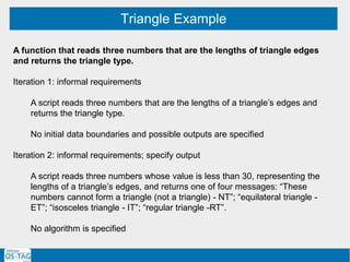
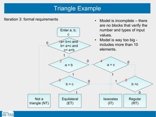
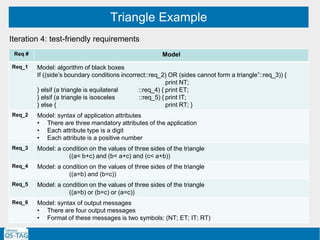
Download to read offline

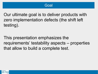
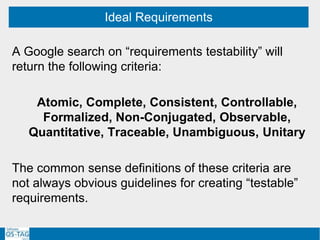
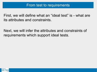
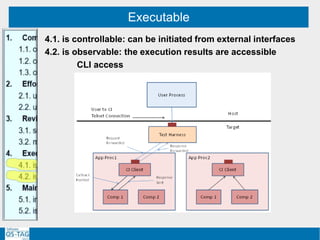
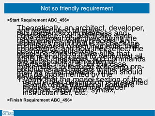
![Object – behavioral view
Higher level entities
Low level entities
APIs Messages
System
settings
Faults
IQXC
(1) SCN E/NA/NA
(2) framer reset (link)
TU
(1) ACN (PhaseEnable)
CPRI Driver
if (SelfTest [GRro] eq "PASS" and SelfTest[SEro] eq "PASS
and SelfTest[PTMro] eq "PASS“)](https://image.slidesharecdn.com/softwareqstag201710202-180525191656/85/Model-Driven-Testing-requirements-models-test-34-320.jpg)
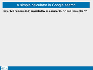
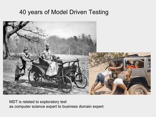
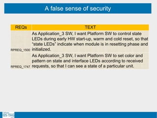
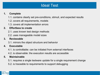
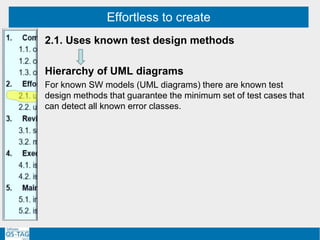
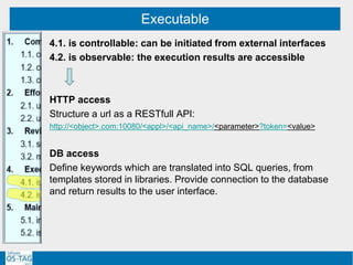
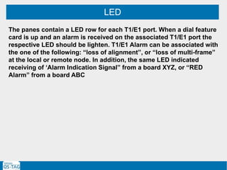
![A simple calculator in Google search
Enter two numbers (a,b) separated by an operator (+,-,*,/) and then enter “=”
Iteration 1:
Enter input string: [+-]?d+([,.]?d*)[+-*/]?d+([,.]?d*)=
Observe result as d+(.?d*)](https://image.slidesharecdn.com/softwareqstag201710202-180525191656/85/Model-Driven-Testing-requirements-models-test-66-320.jpg)
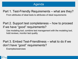
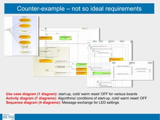
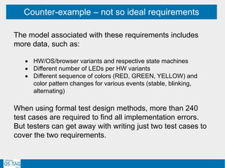
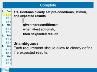
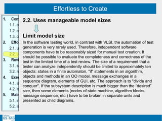
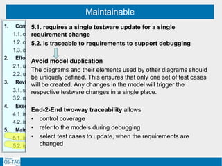
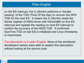
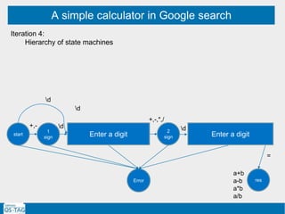
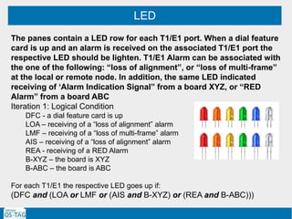
![A simple calculator in Google search
Enter two numbers (a,b) separated by an operator (+,-,*,/) and then enter “=”
Iteration 1:
Enter input string: [+-]?d+([,.]?d*)[+-*/]?d+([,.]?d*)=
Observe result as d+(.?d*)
Iteration 2: State machine
2
sign
1
bef
1
after
1
dot
1
sign
start
res
2
bef
2
dot
2
after
Error
d
+,- d
d d d
dd
+,-,*,/
,. ,. d
+,-,*,/
d
=
=
a+b
a-b
a*b
a/b](https://image.slidesharecdn.com/softwareqstag201710202-180525191656/85/Model-Driven-Testing-requirements-models-test-67-320.jpg)

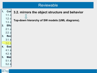
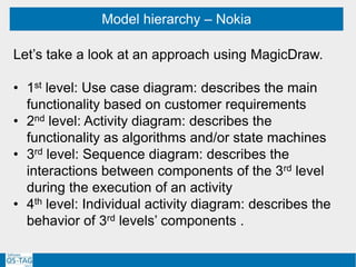
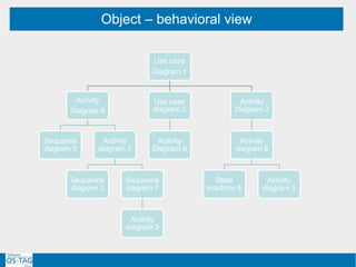
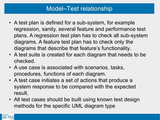
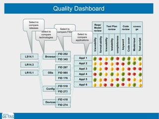
The document discusses ensuring requirements are test-friendly and models support test completeness. It proposes three lines of defense: 1. Using a modeling tool to represent objects in a hierarchical structure of UML diagrams of manageable size. This helps create complete tests using known methods. 2. Incorporating test management into the modeling tool to link test cases to models in a traceable hierarchy. This supports monitoring test quality. 3. Providing end-to-end reviews of requirements, test plans, scripts and code to check for testability and completeness. Reviews also identify needs for test harnesses.