Launch analysis
•
2 likes•2,409 views

This document describes different coordinate systems and phases of motion used in launch analysis of offshore structures. It summarizes the Launch/Barge coordinate system, Rocker Arm coordinate system, and five phases of motion (Phase 1-5) that describe the structure's motion on the barge during launch. It also provides an overview of the launch analysis capabilities and parameters that can be specified in the analysis.

More Related Content
Similar to Launch analysis
Similar to Launch analysis (20)
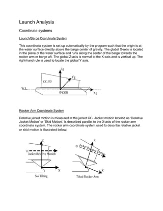
Launch analysis
- 1. Launch Analysis Coordinate systems Launch/Barge Coordinate System This coordinate system is set up automatically by the program such that the origin is at the water surface directly above the barge center of gravity. The global X-axis is located in the plane of the water surface and runs along the center of the barge towards the rocker arm or barge aft. The global Z-axis is normal to the X-axis and is vertical up. The right-hand rule is used to locate the global Y axis. Rocker Arm Coordinate System Relative jacket motion is measured at the jacket CG. Jacket motion labeled as ‘Relative Jacket Motion’ or ‘Skid Motion’, is described parallel to the X-axis of the rocker arm coordinate system. The rocker arm coordinate system used to describe relative jacket or skid motion is illustrated below:
- 2. Phase 1 Motion Phase 1 motion occurs when the structure is sliding on the barge due to winch action and no tipping on the rocker arm has occurred. Barge location, velocity and acceleration are reported with respect to the Launch/Barge coordinate system. Jacket relative displacement, velocity and acceleration are reported with respect to the Rocker Arm coordinate system. The distance to begin tipping estimates the distance the structure CG must travel until tipping is initiated. Phase 2 Motion Phase 2 motion occurs when the structure is sliding on the barge due to gravity or self weight and no tipping of the rocker arm has occurred. Barge location, velocity and acceleration are reported with respect to the Launch/Barge coordinate system. Jacket relative displacement, velocity and acceleration are reported with respect to the Rocker Arm coordinate system. The distance to begin tipping estimates the distance the structure CG must travel until tipping is initiated. Note: If the structure is being pulled by a winch, Phase 2 motion indicates that the structure’s velocity measured along the barge surface exceeds the winch speed. Phase 3 Motion Phase 3 motion occurs when the structure is sliding on the barge due to winch action and is tipping on the rocker arm. Barge location, velocity and acceleration along with jacket displacement and velocity are reported with respect to the Launch/Barge coordinate system. Jacket relative displacement and velocity, labeled as ‘Skid Motion’, are reported with respect to the Rocker Arm coordinate system. The rocker arm angle and pin load are also reported. Phase 4 Motion Phase 4 motion results from the structure sliding due to self weight (gravity) and is tipping on the rocker arm. Barge location, velocity and acceleration along with jacket displacement and velocity are reported with respect to the Launch/Barge coordinate system. Jacket relative displacement and velocity, labeled as ‘Skid Motion’, are reported with respect to the Rocker Arm coordinate system. The rocker arm angle and pin load are also reported. Note: If the structure is being pulled by a winch, Phase 4 motion indicates that the structure’s velocity component parallel to the barge surface exceeds the winch speed.
- 3. Phase 5 Motion Phase 5 motion is motion that occurs after the structure and barge have separated. Barge location, velocity and acceleration along with jacket displacement and velocity are reported with respect to the Launch/Barge coordinate system. The clearance between the jacket and the mudline is also reported. General Capabilities 1. The motion phase of the jacket is automatically classified. 2. The weight and drag of modeled beam and plate elements is calculated automatically. 3. A load case with member distributed and joint concentrated loads is generated for any time step. 4. Weight and/or buoyancy can be added in the Launch input file to account for the weight and/or buoyancy of un-modeled items. 5. Drag areas can be specified in the Launch input to account for the drag of un-modeled items. 6. Ability to specify current with varying direction versus depth. 7. Automatic determination of barge weight and hydrodynamic characteristics based on dimensions input by user. 8. Initial analysis velocity due to a winch may be specified. 9. A time history analysis may be executed starting from the initial jacket position on the barge and ending at either a specific phase or a designated time point. 10. A Launch analysis may be restarted from the structure position at the final time step of a previous analysis. 11. A Post Launch analysis may be executed where load cases consisting of Launch loads for a particular time step are created.
- 4. Analysis Control Parameters (TIME input line) Minimum Launch Time Step: Since a variable time step integration procedure is used, a minimum time step is necessary to prevent the program from reducing the time step to an infinitesimal value. However, a minimum time step value should be sufficiently small so that the analysis can proceed past any step (default 1.0E-8 seconds). Error Control Parameter : Parameter to control the buildup of errors during the time step integration process. This factor is applied to the built-in error controls such that a factor of 1.0 (default) normally keeps the error buildup within satisfactory limits. If the minimum integration time step limit is reached, it may become necessary to increase this tolerance factor or to decrease the minimum allowable integration time step.
- 5. Jacket Orientation (JACKET input line) Jacket Joints on Barge: Three joints specified are used to define the face or plane of the jacket contacting the barge. The structure is aligned on the barge such that the first two joints specified form a line perpendicular to the Launch direction at the back of the barge. The third joint is assumed to be coplanar and forward of the first two joints. Distance from Barge Front to First Joint : This is used to define the location of jacket along the barge length. This distance from the forward end of the barge to the structure 1st joint is shown as d in the figure below. Length of Launch Framing: Used to define the length of the launch truss or launch framing on the jacket as defined by dimension l in the figure below. The length of launch framing is measured from the bottom of jacket. Jacket Center Line Offset: Used to define the offset of the jacket structure from the centerline of the barge as defined by dimension e in the figure below.
- 6. Barge Dimensions (BARGE1 input line) A - Height of Barge B - Width of Barge C - Bottom Length of Barge D - Forward Extension of Barge E - Aft Extension of Barge Number of bottom and side increments : The number of divisions for the barge bottom and sides are used for drag calculations.
- 7. Skid, Rocker Arm and Barge Coefficients A - Skid Height B - Rocker Pin Location C - Rocker Arm Depth - Spacing between Rocker Arms (see barge dimensions diagram) Winch Speed (ft/sec - m/sec) Drag Coefficient (Default 1.0) Added Mass Coefficient (Default 1.0)
- 8. Other Input Data AREA – Input additional drag areas. ANCHOR –Describes anchors restraining barge motion. LCSEL – Converts load cases in SACS model file to weights. INCWGT – Include weights from SACS model file. WEIGHT – Add additional weights or buoyancy data. FRICT – Describe coefficient of static and dynamic friction (per velocity) between barge and jacket structure. CURR –Introduce effects of current on Launch Analysis Launch Runner Report The contact point coordinates are measured from the rocker pin to jacket coordinate system
- 9. Post Launch Analysis The Launch program module may be used to generate an unbalanced load case for any time step of a previously executed Launch analysis. This procedure is called a Post Launch analysis. Post Launch analysis requires the Launch restart file created by the standard Launch analysis execution and a Post Launch input file. In general, the standard analysis input file may be used as the Post Launch input file with only minor modifications. The Post Launch analysis yields an output structural data file containing the model and the unbalanced load cases. The load case(s) created contain unbalanced loads since they do not include the reactions at the jacket/barge interface. Therefore, the jacket model used for the subsequent static analysis should be restrained at these interface joints, thus yielding the reactions. Note: When executing the static analysis, only interface joints that are in contact with the jacket and barge, that is, yield compressive reactions, should be restrained. Launch Runner Definition (LRUNR input line) The jacket structure joints lying on the Launch runner that are to receive Launch runner reactions are specified using LRUNR lines. The first LRUNR line of the set must be a header card. The location of the runner is designated as left or right by entering ‘L’ or ‘R’ in column 7. The left runner is on the barge +Y side and the right runner is on the barge -Y side as shown below:
- 10. Designating Load Case Time Points (LLODA input line) The time points at which a SACS load case is to be generated are designated using the LLODA line. The load case name and the time selection criteria, that is, whether the load case is for a specified time ‘TME’, initial tipping ‘ITP’, maximum velocity ‘MTV’, maximum translational acceleration ‘MTA’ or maximum angular acceleration ‘MAA’ must be specified.