This document describes an electrical systems design project for a solar-powered unmanned aerial vehicle (UAV). The goals of the project are to design custom electrical systems to efficiently convert, regulate, and distribute solar power, protect and monitor lithium-polymer batteries, and enable radio communication during long-range flight. Key components include flexible solar cells, a battery protection circuit, a solar converter, and an Ardupilot board. The project aims to break the world record for longest distance by a solar-powered UAV and advance the use of alternative energy sources for aircraft.
1. Faculty Advisor: Professor Ambar Mitra & Matthew Nelson
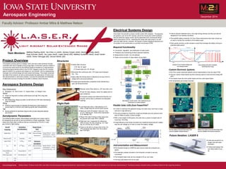
Electrical Systems Design
Required Functionality
Conversion, regulation, and distribution of solar power.
Protection and monitoring of lithium-polymer batteries.
Measurement of pitch, roll, and altitude.
Radio communication to base station during flight.
At its heart, this aircraft is a basic remote control (RC) airplane. The associat-
ed systems, such as an RC receiver, servos for moving the control-surfaces,
and the electronic speed control, will be assembled from commercial off-the-
shelf components (COTS). Extending the range with solar power in an effi-
cient and safe manner, however, will require a custom-designed electrical con-
trol system, to be constructed on a printed circuit board (PCB).
Project Overview
Aerospace Systems Design
Block diagram of entire system. Blue components are pur-
chased, green are custom designed.
The project’s primary goal is to design, build, and test a solar-powered remote-
controlled UAV that is capable of long range flight. A short-term goal for LASER is
to pursue the world record for the farthest distance travelled by a solar-powered
Unmanned Aerial Vehicle (UAV) in the F5-SOL Category under the FAI. Another
goal of LASER is to construct and design an “eco-friendly” UAV by implementing
hydrogen fuel cell technology and solar power technology. This project advances
the state-of-the-science, as well as demonstrates the applications of these scien-
tific advancements in real world contexts. It proves the practicality and feasibility
of alternative sources of energy for aircrafts to address varied missions.
Matthew Poetting (AerE), Yen-Chen Liu (AerE), Zachary Cooper (AerE), Alexander Chally (AerE),
Hugh Schuster (AerE), Jan Lopez (AerE), Logan Heinen (EE), Matthew Gustafson (AerE), Austin Gerber
(AerE), Parker Olthrogge (EE), Devesh Mohan (EE)
Team Members:
Key Dimensions
Wingspan: 14’; Root Chord: 13”; Aspect Ratio: 14; Weight: 6 lbs.
Airfoil
Great low Reynold’s number performance and high lift to drag ratio
Fuselage
Slim lifting body design provides a small amount of lift while decreasing
drag and weight.
Wing
Planform approximates an elliptical lift distribution while keeping in-
duced drag to a minimum and retaining gentle stall characteristics.
Tail
Sizing optimized to decrease drag but still provide adequate stability
and control.
Matthew Nelson, Professor Ambar Mitra, Iowa State University Aerospace Engineering Department. Special thanks to PowerFilm Solar for the donation of our solar array. Special thanks to The Boeing Company, Rockwell Collins, and Alliance Pipeline for their supporting donations.Acknowledgements:
Biaxial carbon fiber sleeve or .25” blue foam core.
Foam for easy shaping, carbon for rigidity and im-
pact resistance.
Computer analysis has determined that this con-
struction will be able to withstand all anticipated
loadings.
Local flight plan with a total distance of 37
miles. (Larger than the current world record)
Starts just north of Hubbard, Iowa and runs
on U.S. Highway 65. Ends at the intersection
of IA Highway 330.
Obeys FAA rules of being 5 miles away from
any airports and under 400 ft. altitude.
Flight plan has 3 waypoints for references
which include: the city of Zearing, U.S. High-
way 30, and the city of Collins.
Picture to the left is a screen shot of the U.S.
VFR sectional map taken from the aviation
app ForeFlight.
Carbon fiber structure
- 1/16” ribs 10” apart
-.5” forward spar and .25” aft spar
Monokote Skin reinforced with 1/16” balsa wood between
the ribs.
Spars slide into ferrule which is attached to the top of the fu-
selage with a structural adhesive.
Provides good aerodynamic properties while maintaining a
light, yet strong structure.
Aerodynamic Parameters
The following table encases critical design parameters and values used in
the designing the aircraft as well as predictions of flight capabilities. These
values are under ideal conditions that are constrained by FAI-SOL 5 cate-
gory limits for flight testing.
Aircraft
Properties
Calculations
and Estimations
Range Calcula-
tions
(400 ft. Altitude)
Weight (lbs.) 6 Lift (lbs.) 5.9986 Glide and Range
Expectations
Range/ Glide (ft.) - 16,417
Total Range (ft.) - 469,875
Total Duration (sec.) - 636
Wing Area (ft2
) 14 Drag (lbs.) .1279
Aspect Ratio 14 (L/D)max 46.90 Endurance
Calculations
CD0 .004 (L3/2
/D)max 32.74 Glide and Range
Expectations
Range/ Glide (ft.) - 14,210
Total Range (ft.) - 424,162
Total Duration (sec.) - 725
Oswald Efficiency
Factor
.8 Airspeed (ft./s) 31.23
Glide Angle (deg.) -1.41 Sink Rate (ft./s) .6658
CL .3752
CD .008
A test bed aircraft for hy-
drogen fuel cell imple-
mentation.
A flying boat design that
can refuel while on wa-
ter.
Flight Path
Lithium polymer batteries have a very high energy density, but they can also be
dangerous if not carefully monitored.
The bq2084 battery protection ICs from Texas Instruments have been chosen as
an way to monitor the conditions of the battery pack.
Solar panels provide a small constant current flow recharge the battery during an
extended glide period.
Flexible Solar Cells from PowerFilm®
In order to maximize the gathered energy, the solar array must have a large
area and a high efficiency.
The array donated by PowerFilm is light and flexible and can produce more
than 20 Watts of power in direct sunlight.
With a total weight of 200 grams, the cells have a power-to-weight ratio of
more than 100 W/kg.
A high-efficiency buck-boost converter from National Semiconductor reliably
step the cell voltage up or down to match the battery voltage.
Custom Electronic Systems
All of the custom electrical systems will be implemented on two four-layer PCB.
The two custom made boards are from previous years of work and are energy effi-
cient.
The boards have two inner power layers and two outer signal layers.
All components are surface mounted.
Constant-Current Constant-Voltage Com-
mon charging method
Pulse-charging alternative method for
maximizing solar energy
Instrumentation and Measurement
The Ardupilot brings to LASER its open source code and computer pro-
grams.
The telemetry already included in the Ardupilot is simple to use and
convenient.
The Ardupilot base code can be changed to fit our own need.
The Auto-pilot feature will not be used.
Top View: Battery Protection Board (top), Solar
Converter (Middle), Ardupilot (bottom)
Bottom View: Battery Protection Board (top), Solar
Converter (Middle), GPS attachment (bottom)
December 2014
Structures
Future Iteration: LASER 6