This document is a design report for an unmanned aerial vehicle (UAV) intended to help map glacial retreats in Greenland. It outlines the concept design process, including defining mission requirements, team member roles, and conducting a competitor survey. The preliminary and detailed design processes are then described, covering aircraft aerodynamics, structure, powertrain, materials, control systems, stability, weight, and performance. Testing procedures such as structural testing, aircraft scaling, stability testing, and flight simulation are also summarized. The report concludes with sections on aircraft costing, risks, and conclusions.

![Design Report
Absolute Zero
University of Swansea
Abstract
A detailed design report has been carried out for the purpose of creating an Unmanned Aerial Vehicle (UAV)
for scientific research in the mapping of glacial retreats in Greenland. A comprehensive look into how and why
the aircraft looks and performs the way it does along with costings to determine the viability of creating a UAV fit
for this purpose.
1. Introduction
Unmanned aerial vehicles (UAV) are becoming more
prominent due to their versatility and abilities to com-
plete tasks that man can not always accomplish. UAVs
are no longer only used for military applications but
are starting to become viable options for scientists and
hobbyists alike. UAVs or drones are divided into two
main categories, remote controlled or autonomous. For
the purpose of this design report an autonomous drone
was chosen due to the large range required.
Glacial retreats are slowly being recognised by the
general public as a problem due to what may happen
if glaciers start to disappear from around the world.
‘Glacier mass balance’ is the key to understanding glacial
retreats, this balance is the yearly addition of frozen
water to the yearly melted water determining whether
the glacier is healthy or in retreat.[1] If glaciers from
around the world were to disappear then it would leave
regions without fresh drinking water effecting animals,
wildlife and over a longer period of time sea levels.[2]
The aim of this project is to help develop a scientific
resource that allows glaciologists to map and keep record
of glacial retreats more easily and relatively quickly al-
lowing for preservation of these prehistoric glaciers.
2. Concept Design Process
2.1. Team Role Agreement
Based on individual’s strengths an agreement to
which roles each members would specialise in along with
a secondary role for support, Table 2 shows each member
and there specified subject area.
2.2. Mission requirements
As part of this design a guideline has been provided
with the minimum values required from the aircraft.
Certain values have been upgraded as it was felt the
benefits of producing an aircraft with certain capabilities
would be favourable to the mission.
Table 1: Mission requirements
Minimum desired
Take off distance 20m 20m
Range 60km 90km
Gust conditions 20 − 30km/h 30 − 40km/h
Cruise speed 50km/h 50km/h
Service ceiling 1000m 1000m
Payload 500g 1kg
cost £1000 under £1000
Reusability Yes Yes
Due to Greenland’s unforgiving weather and how
quickly weather fronts can form, were some of the key
factors in changing values in Table 1. Gusty conditions
are a major concern due to the mountainous regions
therefore the decision to design a more stable aircraft
was chosen. Range was increased incase areas of in-
terest arise during a mission along with an increase in
payload to lift better camera equipment or measuring
equipment. A challenge was set within the design to
create an aircraft under budget however this was not a
vital consideration in component costing.
2.3. Competitor Survey
To fully understand market needs and define a niche
in the market a competitor survey was conducted.
Table 2: Team Role Agreement
J.Jacob J.Johnson I.Milodowski D.Parish M.Rowland-jones M.Satha W.Shackley J.Tang
Specialisation Structure Materials & Propulsion Dynamics & Stability Aerodynamics Structural Weight & Performance Aerodynamics Control Systems
Secondary Role Dynamics & Stability Weight & Performance Structure Control Systems Aerodynamics Materials & Propulsion Structure Aerodynamics
4](https://image.slidesharecdn.com/7fd4de17-6249-4c85-8b38-20b9bbf3e1cd-160112142054/85/Final-year-Design-Report-4-320.jpg)
![Hirrus UAV [15]
Specifications Hirrus UAV
Weight 7kg
Max speed 130 km/h
Flight time 180 mins
Range 30km (auto pilot)
Payload 0.7kg
Service Ceiling 3 km
Aeromapper 300 [16]
Specifications Aeromapper 300
Wing span 3m
Fuselage length 1.23m
Material carbon fibre fuselage and fiberglass payload bay
Take off hand launch or launcher
Empty weight 3.6kg
Takeoff weight 5.2kg
Cruise speed 58km/h
Max speed 120km/h
Endurance 90mins
Cost £10, 200 all included](https://image.slidesharecdn.com/7fd4de17-6249-4c85-8b38-20b9bbf3e1cd-160112142054/85/Final-year-Design-Report-5-320.jpg)
![Mugin 2600 UAV [17]
Specifications Mugin 2600 UAV
Wingspan 2.6m
Weight (No Engine) 6.5kg
Max Take Off Weight 15kg
Payload 4kg
Cruise Speed 120 km/h
Flight Time ~2 Hours
Cost £700 airframe
DuraFly Zephyr V-70 [19]
Specifications Zephyr V-70
Wing span 1.53m
Fuselage length 1m
Material Expanded PolyOlefin
Take off Hand launch or
launcher
Motor EDF 500 watts
Takeoff weight 1.15kg
Specifications Skywalker X8
Wing span 2.12m
Material Expanded PolyOlefin
Take off Hand launch or launcher
Motor 400-800 watts
Takeoff weight 3.5kg
Cost £110 empty shell
Specifications UAV 3000
Wing span 3m
Fuselage length 1.5m
Material Glassfiber/ply fuselage
Take off Hand launch or launcher
Empty weight 5.2 kg
Takeoff weight Dependant on motor up to 2
kg
Cost £ 180 empty shell
UAV
3000
[20]
Skywalker X8 [18]](https://image.slidesharecdn.com/7fd4de17-6249-4c85-8b38-20b9bbf3e1cd-160112142054/85/Final-year-Design-Report-6-320.jpg)
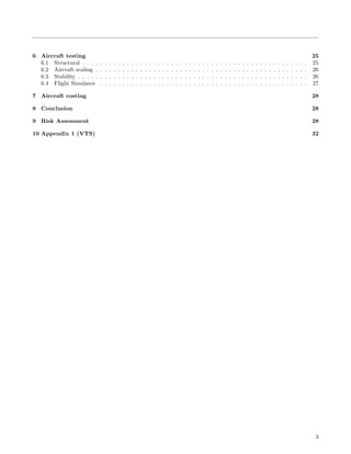
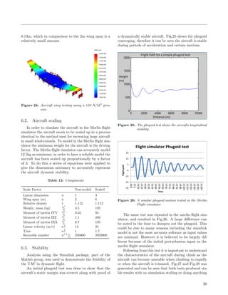
![Figure 1: Positioning map detailing niches in the market
where this design hopes to sit
After initial research into each area multiple drones
were picked for further consideration. A quick table
detailing each aircrafts properties along with a picture
of each aircraft can be found above. From here a po-
sitioning map was created using a marketing tool that
allows users to find niches in the market. Fig1 shows
where each UAV fits in the market and where the aircraft
detailed in this reports aims to fit in.
3. Regulations
It is important to understand the regulations that
may effect the design of the UAV. Although the aircraft
will be flown in Greenland where the UAV regulations
are much more relaxed, it was important the UAV is able
to conduct missions within the UK for testing purposes.
Under the Civil Aviation Authority two key concerns
dictate the need for a permission of flight:
• Is the aircraft flying on a commercial basis (i.e
conducting ‘aerial work’)
• Camera or surveillance equipment fitted to the
aircraft within congested areas.
Although the aircraft will not be working on the basis
of monetary gain it will still be conducting work for an
organisation therefore a certificate will be required to fly
the aircraft. The second key parameter will however not
apply to this aircraft due to the surveillance or camera
equipment not operating in congested areas.[3]
UAVs are classified into 3 types based on overall
weight. Class 1 under 20 kg, class 2 between 20-150kg
and class 3 anything above 150kg. A certificate of Air-
worthiness is required for any UAV over the weight of
150kg, for the purpose of this project it will not be
required due to a very low weight under 10 kg.[4]
4. Preliminary Design
From detailed calculations and research, each area of
the conceptual design was looked into and accessed for
viability and purpose ultimately determining the final
aircraft at the preliminary stage.
4.1. Aerodynamics
4.1.1 Aerofoil selection
Reynolds numbers are a vital step in choosing an
aerofoil. A low reynolds number (Re) is favourable
due to low Re values experience more laminar flow and
therefore the aircraft will produce more efficient wings
generating lift.
Re =
ρV c
µ
(1)
From Equation (1) a value of Re = 250000 was found
allowing for the comparison of multiple aerofoils.
Figure 2: Comparison of multiple Aerofoils over four key
areas at the given reynolds number
The generation of the graphs in Fig.2 were produced
by Xfoil,[5] a program and analysis tool available for
aerofoil selection. The program was developed at MIT
and is only applicable if certain criteria are not met
i.e Compressible flow, Viscous Flow, etc... Based on
the low reynolds number and the values calculated by
Xfoils, the NACA 2412 was chosen due to its low drag
properties and relatively high Clmax. Initial studies into
the NACA 2412 using both Tornedo[6] and XFLR[7]
which will be discussed later on, yielded low values of
lift. Two possible options are to increase surface areas,
mainly wing span, or change the aerofoil to a higher
camber therefore generating more lift. The decision to
change to a NACA 6412 was chosen due to changing the
wing span by the amount needed would have resulted in
a difficult aircraft to launch.
8](https://image.slidesharecdn.com/7fd4de17-6249-4c85-8b38-20b9bbf3e1cd-160112142054/85/Final-year-Design-Report-8-320.jpg)
![4.1.2 Aerodynamic characteristics
To determine the aerodynamic characteristics of the
wing geometry and performance, multiple methods were
used. The advantage of using multiple methods meant
that these calculations could be made more accurate.
The following is a brief explanation of how each theoret-
ical method works.
Prandtl Lifting Line theory assumes that there is
only one horseshoe vortex for each wing segment, thus
making the wing finite. The theory predicts the distribu-
tion of lift generated along the span of the wing through
its three dimensional geometry. The strength of this
vortex reduces along the span. To ease calculations the
theory does not take into account the following; Com-
pressible flow, Viscous Flow, Swept Wings, low aspect
ratio wings and unsteady flows. The use of this theory
revolved around using different aerofoils from an aerofoil
generating software online known as airfoiltools.[8] From
this website estimations of Coefficient of lift properties
were taken from graphs which showed the characteristics
of each aerofoil. This was then introduced into the ap-
propriate equations to calculate the Coefficients of drag
and lift.
CL =
2L
ρv2S
(2)
CD = Cd0 +
C2
l
πeAR
(3)
Results from equations (2) and (3) can also be used to
determine the optimum angle of attack to fly at a given
wing geometries through the greatest CL/CD ratio.
Vortex Lattice Methods models the lifting surfaces
of a wing by assuming that the wing is an infinitely thin
sheet made of small vortices, this is influenced mainly by
the thickness of the sheet. It is an extension of Prandtls
lifting line theory however instead of the theory assuming
that there is a single vortex per wing segment a lattice
of these vortices are generated. To simplify calculations
the software makes the following assumptions; the flow
is incompressible, inviscid and non-rotational.
The lifting surfaces are assumed to be thin and the
influence of the thickness is neglected. It is also assumed
that the angle of attack and the angle of sideslip are both
negligible. Two different types of software were used to
do these calculations both with different advantages over
the other. Tornado which allows ease of design of the
wings through coordinate systems, which creates three
dimensional lifting surfaces such as the wings, horizontal
and vertical tails. However this software lacked the abil-
ity to create a fuselage and simulate how the fuselage
would interact with the lift generating surfaces. The sec-
ond was a program called XFLR5 which uses the same
interaction system as Tornado however has the ability to
create a fuselage and shows the effect this will have on
the wings and also has some very basic computational
fluid dynamics entwined into the software to produce
graphical representations of flows.
Table 3: Aerodynamics characteristics based on multiple
methods
NACA 2412 NACA 6412
Wing Span 3 2.4
Mean Geometric Chord 0.3 0.25
Reynolds number 290000 220000
Wing inclination 4 3.7
Tornado
CL 0.54 0.75
CD 0.009 0.024
XFLR
CL 0.44 0.8
CD 0.01 0.024
Finite wing method
CL 0.55 0.692
CD 0.02 0.05
Table 3 shows the two key iterations and the differ-
ence between both theories.
4.1.3 Aircraft changes
First iteration: Originally a weight estimation of 6kg
meant that the coefficients of lift and drag were calcu-
lated to produce enough lift for the aircraft to fly at
straight and level un-accelerated flight where lift is equal
to weight. Using a constant chord is often used where
low cost is important because of their ease to build and
manufacture, but they are less efficient in the outer sec-
tions of the wing. Through structural analysis the wing
span overall was not needed and could be shortened to
reduce loading factors caused by the span of the wing
and amount of material used.
Second iteration: With the estimated mass of the
aircraft still at 6kg, it was determined that changing
the aerofoil to a NACA 6412 meant that more lift could
be generated because of the increase in camber of the
aerofoil. This also allowed for partitions of the wing to
be tapered so to increase the aspect ratio of the wings
making them more structurally and aerodynamically ef-
ficient by reducing wing tip vortex strength. It was also
slightly swept back so as to increase the aerodynamic
stability. The change in aerofoil also meant that there
was now a larger CLmax available, this means that the
distance required to take off would be shortened, along
with better stall characteristics.
9](https://image.slidesharecdn.com/7fd4de17-6249-4c85-8b38-20b9bbf3e1cd-160112142054/85/Final-year-Design-Report-9-320.jpg)
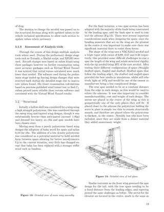
![4.2. Structural Design
The design of certain features were governed by the
research from the aerodynamics, such as the wing shape
and aerofoil, and this evolved as time went on. The
main difference from the original wing concept was the
introduction of a taper ratio of 0.5 and increasing the
sweep to 10 degrees.
One of the conceptual designs for the internal struc-
ture of the wing was to produce a hollow shell with a
spar. This was produced to try and reduce weight while
remaining as strong as possible, however when trying
to optimise weight and structural integrity it was found
reducing the wall thickness of the aerofoil to reach an
optimal weight was problematic for structural loads.
It follows that a more classic ribs and spar configu-
ration has been adopted and the material selection has
increased stiffness and reduced weight. The tail geom-
etry again changed with the larger single-vertical tail.
Identical to the front wing, these were originally designed
to be a plastic shell but are now ribs and spars from
the original concept, the fuselage design has changed
substantially: removing the joined front and tail wing
construction as it increased weight too much and chang-
ing the battery choice altered the front hub. With the
shortened hub the design became structurally weaker
due to the point at which the tail of the wing cut into
the fuselage was near where the hub ended creating a
thin section of material, so a new design was looked into
with an additional aim of being more aerodynamically
suited to the flight parameters.
A high lift generating (HLG) fuselage was then de-
signed by using Mathematical optimisation technique
which then favours with more lift and low drag char-
acteristics at lower angles of attack, short landing and
take-off capabilities.[9] The main challenge in the fuse-
lage design was the space requirements and to get a
technical structure which withstands the load factors.
The largest stresses act at the joints where the wings are
connected to the fuselage, thus this area was strength-
ened with a larger wall thickness. Fillets were applied
at the sharper edges which again gives a uniform flow
of the loadings. Hence, the internal structure resists the
tensile and compressive loadings.
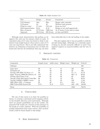
Fig 5 shows an overview of the aircraft design at
this stage along with placement of components. The
placement of each component was derived with the help
of control and stability to ensure a stable aircraft during
flight, see the section on stability.
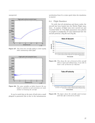
4.2.1 Structural Diagram
A vital part of producing an aircraft is evaluating the
limitations. A load factor, n, can be calculated based
on equations (4) and (5). This graph shows three key
areas, the first is the stall properties of the aircraft this
is important when flying slowly. The top horizontal line
shows the structural limitations in-terms of manoeuvres,
the last line is the the vertical line where a maximum
speed is applied before structural loads become too high.
n =
q
W
S
CD0
k
(4)
n =
qπAe
W
S
[(
T
W
)max −
qCD0
W
S
] (5)
This can be depicted as a ‘V-n’ diagram found in
Fig. 3.
Figure 3: Structural limitations of the aircraft
10](https://image.slidesharecdn.com/7fd4de17-6249-4c85-8b38-20b9bbf3e1cd-160112142054/85/Final-year-Design-Report-10-320.jpg)
![Figure 5: Aircraft cross section along with component placing based on CG calculations
4.3. Powertrain
4.3.1 Motor selection
There are many types of engines ranging from elec-
tric propeller driven , diesel propeller driven, electric
ducted fan (EDF) and jet engines. Initially both jet
engines and electric ducted fan were ruled out due to
there lack of efficiency. EDF systems are designed to
operate at large RPM and produce large amounts of
thrust however, they are predominantly used in the RC
world as motors installed in model jet fighters reaching
large speeds and relatively low flight times, this was
decided, for the purpose of this mission inadequate. Jet
engines become very inefficient when scaled down to
the size we need, they also generally have high specific
fuel consumption compared to a small diesel or petrol
propeller driven aircraft therefore this motor was also
ruled out.
When comparing an electric motor versus a diesel or
petrol engine the main differences are in efficiency and
weight. With recent advances in brushless technology
electric motors can reach anywhere from 75%-85% effi-
ciency much higher than internal combustion engines.[10]
The weight of a petrol or diesel engine is much higher
increasing the aircrafts overall weight, not a desirable
feature. Due to the small thrust requirements produced
by weight and performance along with aerodynamics
results the choice for a mid powered electric engine was
chosen producing roughly 200 watts of power.
4.3.2 Propeller selection
There are two main aspects to all propellers, the di-
ameter of the propeller and the pitch of the blades. The
diameter of the propeller is the distance from tip to tip,
the pitch or twist of the blade is defined as the distance
the propeller would move the airplane forward in one
rotation in a perfect world. However this is impractical
as perfect conditions will almost never arise due to the
fact that propellers are never 100% efficient and this is
also considering an incompressible flow.[11] Although at
the speeds the aircraft is flying it would typically not
encounter compressibility effects it may be encountered
at the tips of the propeller.
The effects of the diameter of the propeller in general
will result in a larger amount of thrust produced by the
engine, whereas the pitch will increase the speed of the
aircraft. For example a small diameter coupled with a
large pitch will move faster through the air however only
move small amounts of air meaning it will be perfect
for small aircraft looking to move fast. A large diame-
ter propeller with a shallow pitch angle will move large
amounts of air meaning large amounts of thrust but the
shallow pitch angle means it will move through the air
more slowly.[11]
Based on Fig.6 and the more desirable shallow pitch
and larger diameter it can determined that a propeller
size of 10 × 5 is more desirable for the Greenland appli-
cation. The choice of propeller size also means that an
increase in torque benefits Take-off and Landing proper-
ties of the aircraft.
12](https://image.slidesharecdn.com/7fd4de17-6249-4c85-8b38-20b9bbf3e1cd-160112142054/85/Final-year-Design-Report-12-320.jpg)
![Figure 6: Propeller sizing guild based on engine size[12]
4.4. Material selection
The material selection was based on work completed
by the structural group along with the help of the Edu-
pack software. The structural design allowed for a maxi-
mum of 1000kg/m3
for critical components and a min of
100kg/m3
. From these values a list of possible materials
were chosen based of manufacturing routes, structural
limitations and overall viability for the aircraft. During
the detailed design phase materials will be assessed and
simulated to verify functionality. A short list of possible
materials for key component will be carried forward are:
• Nylon 6 10
• High density polystyrene
• hard wood, Spar
• Balsa wood
4.4.1 Aircraft changes
The conceptual design brought forward featured two
engines mounted on the underside of the wings. The
two engine configuration has since been dropped to a
single engine due to two main reasons, the first of which
is weight. Due to the relative lightness of the proposed
aircraft, having two very small engines produce the same
amount of thrust as having one slightly larger engine
with next to no real benefits with regards to excess
weight. The second reason is due to the effect it will
have on the range of the aircraft. Most brushless engines
will have a 75-85% efficiency therefore losses associated
with having two engines is much higher than just one
single engine. Not only do the losses in efficiency reduce
the range of the aircraft but due to each engine drawing
separate currents, the amount of energy needed for both
engines will far exceed that needed for one single engine.
Towards the end of the preliminary phase a prob-
lem was found in the design and material choice for the
fuselage therefore a complete overhaul of structure and
material choice was done which will be discussed later
on.
4.5. Control Systems
Due to the difficult nature of the mission a detailed
look into the flight controls and telemetry for the aircraft
has been conducted. The Greenland project requires an
aircraft that is autonomous and able to capture images
of the landscape it is flying through.
Multiple autopilot systems have been studied and
the AMP 2.6 board with GPS is a viable option at this
current stage. It includes 3-axis gyro, accelerometer,
magnetometer, barometer and other high performance
recording instruments that can be streamed live to the
ground station while in range or recorded while out of
range. The system also features an open source autopi-
lot systems using Invensenses 6 DoF Accelerometer and
Gyro MPU-6000.
Camera equipment is one of the most important as-
pects of design. The mission requires scientists to analyse
pictures captured from the aircraft to help map glacial
retreats. The initial design was to have two cameras, the
first facing forward and the main camera facing down
mapping the landscape. However due to the aircraft
changing from 2 engines to 1 engine, there is no longer
room for two cameras therefore one main camera will be
pointing down mapping the landscape. A GoPro hero 4
will be used as a high resolution device is needed.
Research on battery quantity and quality has been
carried out and there are clear advantages using LiPo
battery packs. Calculations have been conducted:
Batterylife =
mAh
mA
× 0.7 (6)
Based on Equation 6, where an efficiency of 70%
was used for environmental factors, and values found
by the propulsions section it was determined that two
high capacity LiPo batteries will be required for the
given flight time however three will be used for extra
range allowing for a safety factor and redundancies. The
batteries under consideration at this time is the Zippy
Traxxas 7600mAh 2S 1P 30C.
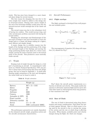
Table 14 shows the current selection of equipment
proposed for this mission along with dimensions and
weight of each component.
13](https://image.slidesharecdn.com/7fd4de17-6249-4c85-8b38-20b9bbf3e1cd-160112142054/85/Final-year-Design-Report-13-320.jpg)
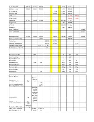
![Table 4: Control Systems
component Length (mm) width (mm) Height (mm) Weight (g)
Ardupilot 2.6 70 40 10 32
Turnigy MX-353S 17g Servo x 4 38 13 27 17 × 4
Zippy Traxxas 7600mAh Battery x3 157 25 45 367 × 3
Turnigy Dual Power Unit 100 50 20 89
Turnigy Plush 60A Speed Controller 80 31 14 60
Turnigy D3536/8 1000KV motor 52 35 35 102
3DR uBlox GPS + Compass 38 38 8.5 16.8
3DR Video/OSD System Kit N/A N/A N/A 100 − 150
Total 1594
4.5.1 Aircraft changes
Due to the amount of components to fit within the
fuselage it was required at an early stage to help re-
design the fuselage to accommodate all necessary flight
equipment. Although this can not be seen externally,
internally new compartments where created.
4.6. Stability
For an aircraft to be stable it must, after a period
of time, return to an equilibrium point in flight follow-
ing disruptive forces, such as a gust of wind or control
surface deflection. The first task with regards to the dy-
namic and static stability of the UAV was to determine
the static margin. The static margin is defined as the
distance between the centre of gravity and the neutral
point as a percentage of the mean chord. For an aircraft
to be statically stable, the centre of gravity must be
forward of the neutral point, therefore the static margin
must also be positive. Generally a margin greater than
5% [1] should provide sufficient stability.
An increase in angle of attack, α, should generate
a nose-down pitching moment, directing the aircraft
back towards equilibrium. In reverse too, a decrease
in α should generate a nose-up moment, directing the
aircraft once more towards stability.
dCM
dαα
< 0 (7)
At straight, level and steady flight the pitching moment
should be zero, as the aircraft should be in its equilib-
rium position. Therefore:
CMα(αα = 0) < 0 (8)
To calculate the static margin, this equation was used:
CMα = (h − hn)CLα (9)
From this equation, it can be seen that the centre
of gravity must be located in front of the neutral point
in order to achieve static stability. The static margin is
noted as: h − hn. To make the calculation of the static
margin easier, a MATLAB script was written, enabling
it to be calculated quickly during changes to the UAV
parameters.
Taking into account the configuration of the UAV
in the early design stages, the static margin was calcu-
lated to be 0.2359, 23.59%, demonstrating static sta-
bility. With the updated design, this was then revised
to 21.15%, matching also the values achieved from Tor-
nado. However, this value was deemed to be too high to
achieve sufficient manoeuvrability, and the target for a
static margin of around 15% was set, as UAV are usually
expected to have a static margin in the region of 5%
to 15%. To achieve this, the positions of the masses
within the airframe structure were shifted closer to the
neutral point. A static margin of 14.69% ended up being
calculated for the configuration detailed above. Table5
shows the change in CoG based on changes made to the
static margin.
Table 5: Centre of Gravity variation from leading ledge of
wings
Before After
X-CoG 30.7mm 108.46mm
Y-CoG 0 0
4.6.1 Aircraft Changes
The tail design for this aircraft will have a major
effect on stability of the aircraft during flight. Choosing
the correct configuration will make for a more stable
aircraft resulting in clearer pictures and therefore more
accurate aerial photography for the Greenland project.
The tail configuration carried forward from the con-
ceptual design was a twin tail plane, this design was
considered favourable at the time due to its larger surface
area and therefore increased stability during turbulent
14](https://image.slidesharecdn.com/7fd4de17-6249-4c85-8b38-20b9bbf3e1cd-160112142054/85/Final-year-Design-Report-14-320.jpg)
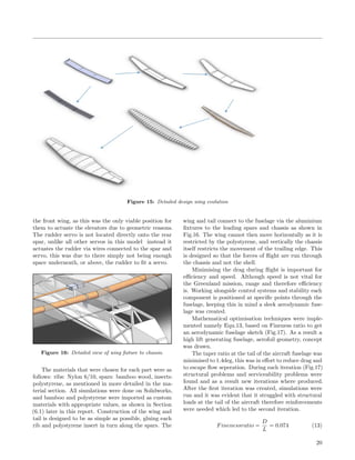
![5. Detailed Design Process
Moving out of the Preliminary design phase where
the aircraft’s overall characteristics have been decided
and early calculations have been conducted to ensure a
functional plane, the aircraft now moves into the detailed
design phase where parameters are refined to ensure ef-
ficiency and more desirable characteristics. During this
stage aircraft modelling followed by aircraft testing has
been accomplished to ensure an aircraft that not only
flies but handles correctly.
5.1. Aerodynamics
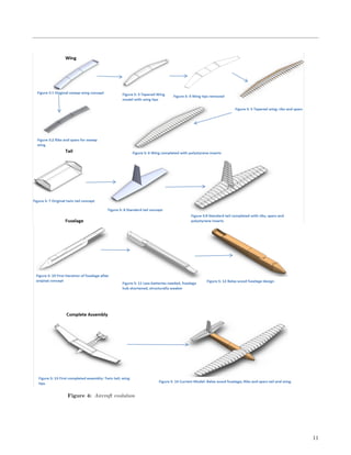
The aircraft wings underwent a large change in shape
for both aerodynamic and structural redundancy pur-
poses. This resulted in an overall aircraft weight reduc-
tion and more sleek aerodynamic geometry allowing for
reductions in drag, Fig.10 shows the evolution of the
aircraft wings from an aerodynamic point of view.
Figure 10: The first iteration is a simple wing, rectangular
in shape, this was then tapered at the ends in an
effort to reduce wing tip strength in the second
iteration. The last and final iteration has an
increased taper ratio along with a semi blended
wing, larger root cord, for structural reasons to
increase stiffness along with increase in lift and
aerodynamic properties.
During the detailed design stage of the project more
realistic software was adopted to verify lift and drag
properties. This was done to verify values that have
already been calculated and to fully understand the
aircraft.
5.1.1 Virtual Wind Tunnel
Virtual Wind Tunnel by Altair[13] is a Computa-
tional fluid dynamics software package designed for au-
tomotive vehicles. The key benefit of this software is
that it uses viscous flow, much more similar to the real
world. Gathering data from the virtual wind tunnel
allows for more accurate calculations for instance lift,
drag, pressure distribution and flow separation.
The Virtual Wind Tunnel works on the utilisation
of the Navier-Stoke equations. It is possible to calcu-
late the forces acting in the X, Y and Z co-ordinate
system, for the purpose of this study, lift, drag and cross
forces (usually negligible) respectively. The values found
are then normalised into values of CL and CD using
equations (2) and (3).
Generating a mesh is extremely important when
testing in the virtual wind tunnel, there are two basic
two-dimensional shapes that are used for meshing. The
benefits of using a triangle is that is it the simplest type
of mesh to create and has the ability to give a more
accurate concave or convex shapes. This is of great
importance when generating a mesh for the UAV as the
wings are in the shape of an aerofoil which is smooth,
any difficult to produce a smooth profile of the wing
which will greatly affect results.
Element size and the maximum deviation of elements
is important to create a fine mesh. The benefit of having
a finer mesh is that it will give more accurate results.
For this test the number of elements created is around
30,000. Which is more than enough for simple geometry
input, to achieve more accurate results a finer mesh
could be generated, however the finer the mesh the more
computationally heavy and time consuming it will be.
The mesh created for the virtual wind tunnel can be
found in Fig.11
Figure 11: Meshing of the aircraft for the Virtual Wind
Tunnel
17](https://image.slidesharecdn.com/7fd4de17-6249-4c85-8b38-20b9bbf3e1cd-160112142054/85/Final-year-Design-Report-17-320.jpg)
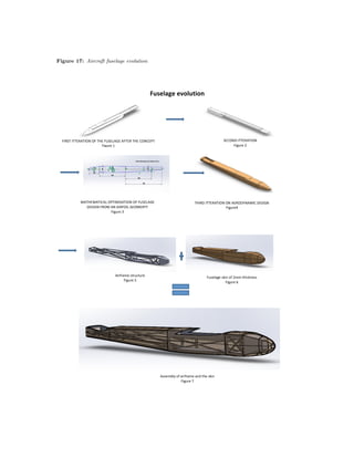
![Multiple techniques were used and as a result, the
third iteration gave a better aerodynamic fuselage, both
in terms of fineness ratio and the tail taper ratio. With
the overall geometry of the fuselage determined, a model
was created ready for testing using a monocoque struc-
ture. Working with the material section it was noticed
that this design made it difficult to service components
and build in conventional managers meaning more com-
plex materials would be required resulting in a heavier
and less stiff fuselage. The fourth iteration was created
using a complete airframe design, where a tray of in-
ternal components could be placed within the airframe
for quick access and ability to swap trays for immediate
relaunch capabilities. Each iteration can be found in
Fig.17.
5.3. Motor
The Power-train in the aircraft has evolved multiple
times over the course of the design. With changes to
aerodynamic performance along with criteria set out by
weight and performance it was crucial that the correct
motor was chosen.
Based on the current drag estimates under straight
and level flight where thrust must equal drag equation
(14) was used to determine power required.
PR = Tv (14)
The value of 56 Watts is required for straight and
level flight, however this value is assuming perfect condi-
tions therefore equation (15) was used to include motor
efficiency, shaft efficiency and propeller efficiency.
PR = Tvηshaftηmotorηpropeller (15)
Based on equations (14) and (15) a total power of
171.5 Watts is needed during straight and level flight.
A certain amount of redundancy is required for take
off, strong winds and any other eventualities that may
occur during a flight. Table 9 shows the characteristics
of the chosen motor.
Table 9: Motor selection
Voltage 7.414.8V
RPM 1000 Kv
Max Power 430 Watts
Weight 102g
Using the current motor and Equ.(6) it has been
found that the aircraft will be able to sustain flight for
up to 1.7 hours.
The propeller, and engine type proposed during the
preliminary design is still fit for purpose therefore a 10×5
will be used along with an electric brushless motor.
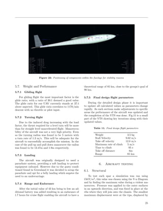
5.4. Material
Edupack[?] was continuously used to determine vi-
able materials based on two key areas, weight and stiff-
ness. The two parameters are vital for wing design and
given by equations (16) and (17)
m = ALρ (16)
S =
CEA2
12L3
(17)
Equations (16) and (17) are substituted into each
other to provide a material index which can then be
applied to the Edupack software.
m = L
12L3S
C
×
ρ
E
1
2
(18)
The information in equation (18) provides important
values to achieve the stiffest and lightest material fit for
purpose, the value of ρ
E0.5 must be as small as possible.
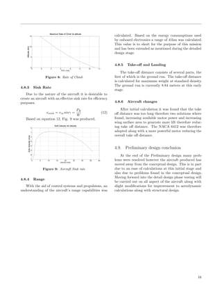
This was applied to Fig.18 and is depicted as the
line that traverses the graph. Everything above this line
is a suitable candidate for material choice however the
higher the Young’s modulus the better. A criteria was
added so that the overall weight of the aircraft did not
rise significantly and therefore a maximum density of
2000 kg/m3
was chosen eliminating metals.
From Fig.18 the decision to use bamboo was adopted
for the main spar. This is due to the high stiffness and
relatively low density.
A light plastic film will be applied to the aircraft
and act as the skin of the UAV. This was chosen due
to its waterproof properties and the heat shrinking that
allows for exact moulding. Low density polystyrene will
be placed in-between each rib to allow for support of the
skin and ensure a perfect aerodynamic shape is kept.
5.4.1 Aircraft changes
Although the material selection has not had a major
impact on aircraft size or shape it has been a major
driving force to completely change the internal structure
of the fuselage. During the second iteration it was no-
ticed that parts were not easily accessible for repairs and
servicing (Fig.15). A larger problem was caused when it
was noticed that the fuselage would have to be manufac-
tured in a very specific way using certain materials that
where not feasible for this mission. Therefore a complete
overhaul of the internal structure of the fuselage was
22](https://image.slidesharecdn.com/7fd4de17-6249-4c85-8b38-20b9bbf3e1cd-160112142054/85/Final-year-Design-Report-22-320.jpg)
![Figure 18: Edupack material selection softare[14]
done. Working along side the structure group a new
airframe system was implemented and allowed for more
material choice and manufacturing route.
The use of 3D printing is a large topic in the world of
manufacturing, the versatility of printing broken parts
along with upgrading components is endless. Therefore
incorporating this was felt as important especially if
scientists are in remote areas, all they would require is
a 3D printer to repair components. This move to 3D
ABS plastics was only possible due to the adoption of
an airframe instead of the heavier monocoque design.
Under testing the ABS plastic was able to withstand
the forces that would be expected from flight.
5.5. Control Systems
The process to determine the sizing of ailerons, rud-
ders and elevators was undertaken by using the Aerofoil
Flap Modeller script in Matlab. It takes the two dimen-
sional curves of the aerofoil used on the UAV, changing
some figures by percentage of the aerofoil chord length
to simulate a virtual control surface at a set range of
deflection angles, calculating the changes in lift coeffi-
cient and centre of pressure from the simulated control
surface.
Figure 19: CoP change during aileron deflection
The Aerofoil Flap Modeller script has been run twice
in order to size the ailerons, rudders and elevators. Fig.19
relate to the aileron sizing; in Fig.19, it indicates that
a smaller aileron with a 20% of the chord length, has
smaller changes in centre of pressure as it deflects, while
it is still generating sufficient lift coefficient changes to
roll the aircraft. The smaller change in centre of pres-
sure is desirable because it does not cause huge changes
in drag produced at the aileron, it will give the air-
craft a benefit in terms of power consumption during
manoeuvring.
23](https://image.slidesharecdn.com/7fd4de17-6249-4c85-8b38-20b9bbf3e1cd-160112142054/85/Final-year-Design-Report-23-320.jpg)
![The same method was used to calculate elevator size
and yielded 50% length should be used for both elevator
and rudder configuration.
Two methods were used to calculate aileron size
based on the aerofoil flap modeller and the second based
on hand calculated that take into account roll rates and
banking moments.
To complete the hand calculations the following val-
ues where used, Wing span = 2m, Take-off weight =
3.5kg, Wing area = 0.5725m2, Aspect Ratio = 6.99, Ta-
per Ratio = 2, Horizontal tail planform area = 0.0983m2,
Stall Speed = 8.67m/s, and Bank angle = 10 degrees
turning in 2 seconds.
ClδA =
2CLawτCr
Sb
[
y2
2
+
2
3
(
λ − 1
b
)y3
]yo
yi
(19)
Equation (19) was used to calculate the roll moment
required for the aircraft, from this the position of the
inboard and outboard aileron should be 60% and 95%
of the wing span respectively. This gave rise to a value
of yi = 0.61m and yo = 0.95m. The difference of these
values allow for the aileron length of 0.34m and the
depth of the aileron was found to be 0.057m, Fig.20 is a
diagram of the ailerons.
Figure 20: Aileron sizing
The calculations fit with the aerofoil flap modeller
therefore these values were deemed satisfactory and
proved sufficient during flight testing.
The sizing for both elevator and rudder were done
on the same bases and yielded the Fig.21 and Fig.22
Figure 21: Rudder sizing
Figure 22: Elevator sizing
5.6. Stability
The XFLR5 program, as mentioned in section 2.1,
allows users to determine where avionics and flight in-
struments should be placed within the aircraft. Using
the measurements of the length of the fuselage that
have been provided, a model of the UAV has been cre-
ated in this software, the user is able to move different
components of the aircraft, the wings and weighted in-
struments within the fuselage. A 3D model has been
produced within the program to determine positioning
of component to enable the structural group to build
compartments for housing all the electronics. This in
turn enabled for a more stable aircraft, Fig.23 depicts
where components should be placed for stability reasons.
Over the course of the design multiple iterations
have been created. Changes in weight, structure and
components all upset the balance of the aircraft. The
re-calculation of the static margin along with a small
shift in Cog was needed to maintain the desired 15%.
The resulting calculations produced Table 10.
Table 10: Centre of Gravity position and component posi-
tioning from nose of aircraft
Distance (m)
CoG 0.48
Battery and camera 0.34
24](https://image.slidesharecdn.com/7fd4de17-6249-4c85-8b38-20b9bbf3e1cd-160112142054/85/Final-year-Design-Report-24-320.jpg)

![References
[1] Nichols.edu. Alpine Glacier Mass
Balance [Internet]. Available from:
http://www.nichols.edu/departments/glacier/mb.htm
[2] Thomas Mlg. Worldwide glacier re-
treat. RealClimate. available at
www.realclimate.org/index.php?p=129
[3] Caa.co.uk. Do I need a Permission for an
Unmanned Aircraft (UAS) — Aircraft —
Operations and Safety [Internet]. Available
from: http://www.caa.co.uk/default.aspx?catid
=1995&pageid=16006
[4] Unmanned Aircraft System Operations In UK
Airspace Guidance, CAP 722. 6th ed. CAA, 2015.
Print.
[5] Web.mit.edu. [Internet]. 2013 Available from:
http://web.mit.edu/drela/Public/web/xfoil/
[6] Redhammer.se. Tornado, the Vortex lat-
tice method. [Internet]. Available from:
http://www.redhammer.se/tornado/
[7] Xflr5.com. XFLR5 [Internet]. 2015. Available from:
http://www.xflr5.com/xflr5.htm
[8] Airfoiltools.com. Airfoil Tools [Internet]. Available
from: http://www.airfoiltools.com/
[9] High lift generating fuselage concept http :
//www.ijetae.com/files/V olume2Issue5
[10] Quantum Devices INC. Brushless Mo-
tors vs Brush Motors, what’s the differ-
ence? [Internet]. 2010 Available from:
https://quantumdevices.wordpress.com/2010/08/27
/brushless-motors-vs-brush-motors-whats-the-
difference/
[11] Brown, M. (2014). Sizing RC Airplane Pro-
pellers. [online] Hooked on RC Airplanes. Available
at: http://www.hooked-on-rc-airplanes.com/sizing-
rc-airplane-propellers.html
[12] Carpenter. P. RC Airplane Propeller Size Guide
[Internet]. Rc-airplane-world.com. 2015. Available
from: http://www.rc-airplane-world.com/propeller-
size.html
[13] Altairhyperworks.com. HyperWorks: Open Archi-
tecture CAE solution [Internet]. 2015 Available
from: http://www.altairhyperworks.com/
[14] CES Edupack. (2014). United Kingdom: Granta.
[15] Hirrus mini UAV system [Internet]. 1st ed.
Bucharest: TeamNet International S.A;
2015 [cited 8 March 2015]. Available from:
http://www.aft.ro/bro.pdf
[16] Aeromao.com. Aeromao - Aeromapper 300 [Inter-
net]. 2015 [cited 2 March 2015]. Available from:
http : //www.aeromao.com/aeromapper300
[17] 3. Fpvflying.com. Mugin 2600 UAV FPV
platform - FPV flying [Internet]. 2015
[cited 18 March 2015]. Available from:
http://www.fpvflying.com/products/Mugin-
2600-UAV-FPV-platform.html
[18] HobbyKing Store. Skywalker X8 FPV / UAV Flying
Wing 2120mm [Internet]. 2015 [cited 12 May 2015].
Available from http://www.hobbyking.co.uk/
[19] HobbyKing Store. Durafly Zephyr V-70 High Per-
formance 70mm EDF V-Tail Glider 1533mm (PNF)
[Internet]. 2015 [cited 12 May 2015]. Available from
http://www.hobbyking.co.uk/
[20] HobbyKing Store. UAV-3000 Composite FPV/UAV
Aircraft 3000mm (ARF) (EU Warehouse) [Inter-
net]. 2015 [cited 12 March 2015]. Available from
http://www.hobbyking.co.uk/
10. Appendix 1 (VTS)
32](https://image.slidesharecdn.com/7fd4de17-6249-4c85-8b38-20b9bbf3e1cd-160112142054/85/Final-year-Design-Report-32-320.jpg)


![[Sapienza] Development of the Flight Dynamics Model of a Flying Wing Aircraft](https://cdn.slidesharecdn.com/ss_thumbnails/355a5afb-e186-4fcb-b8a5-c15a5650ca6a-160412194308-thumbnail.jpg?width=640&height=640&fit=bounds)


