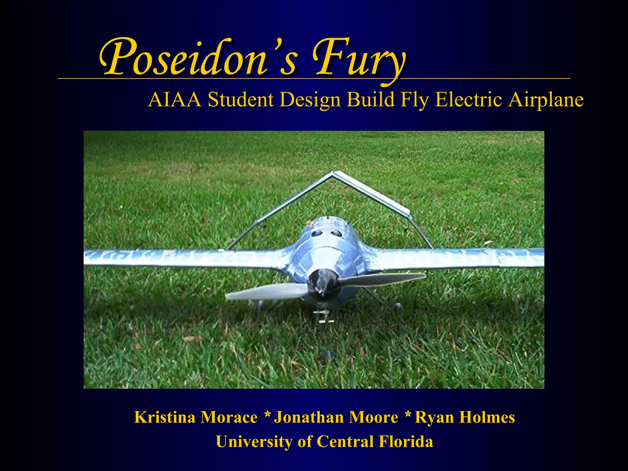
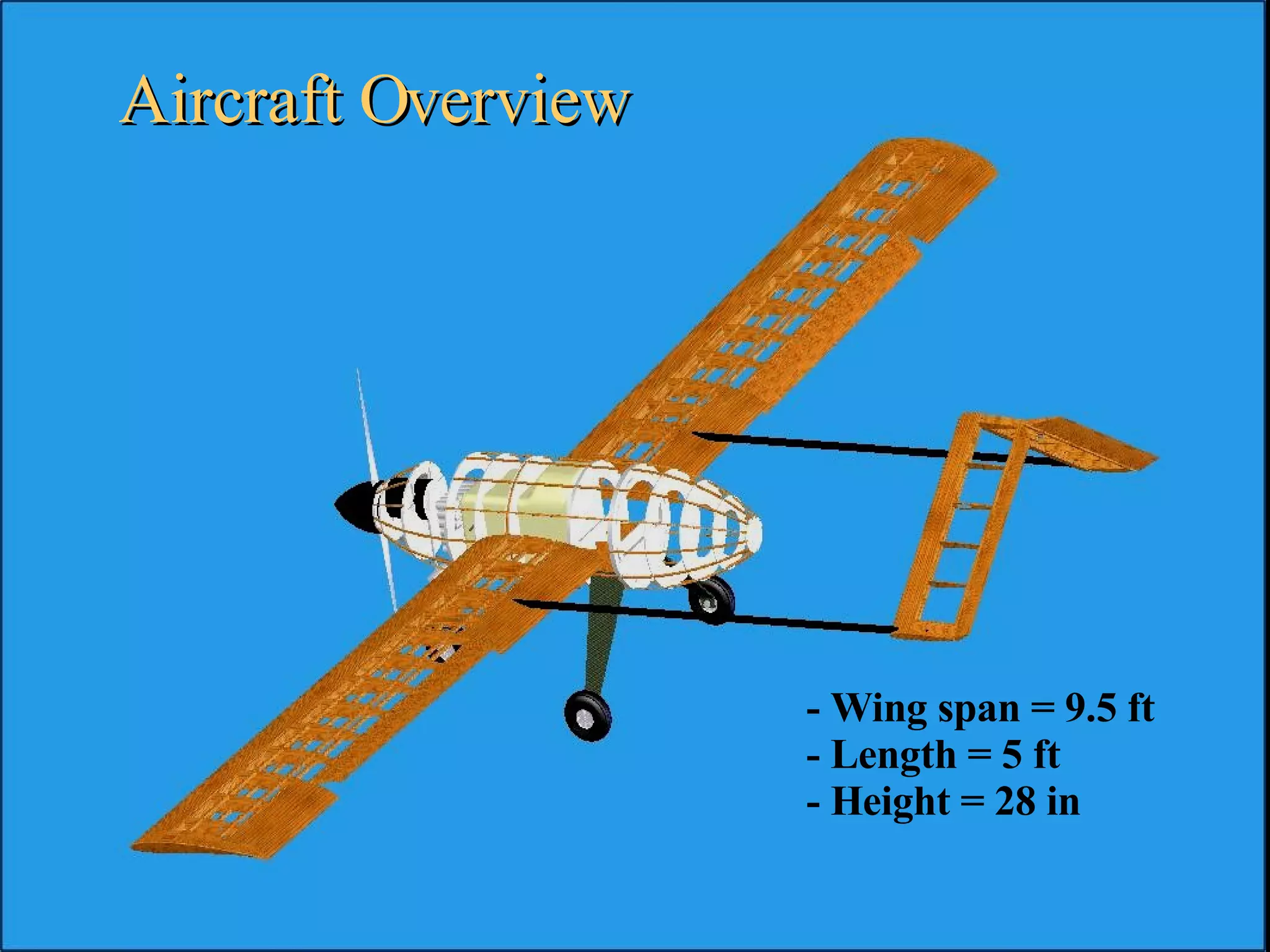
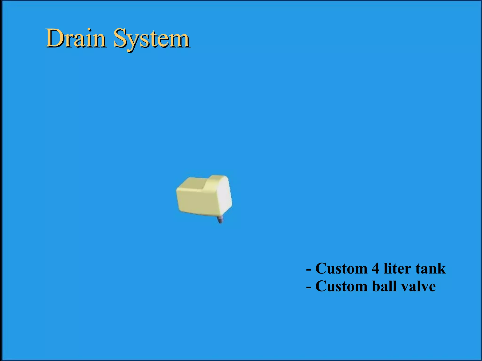
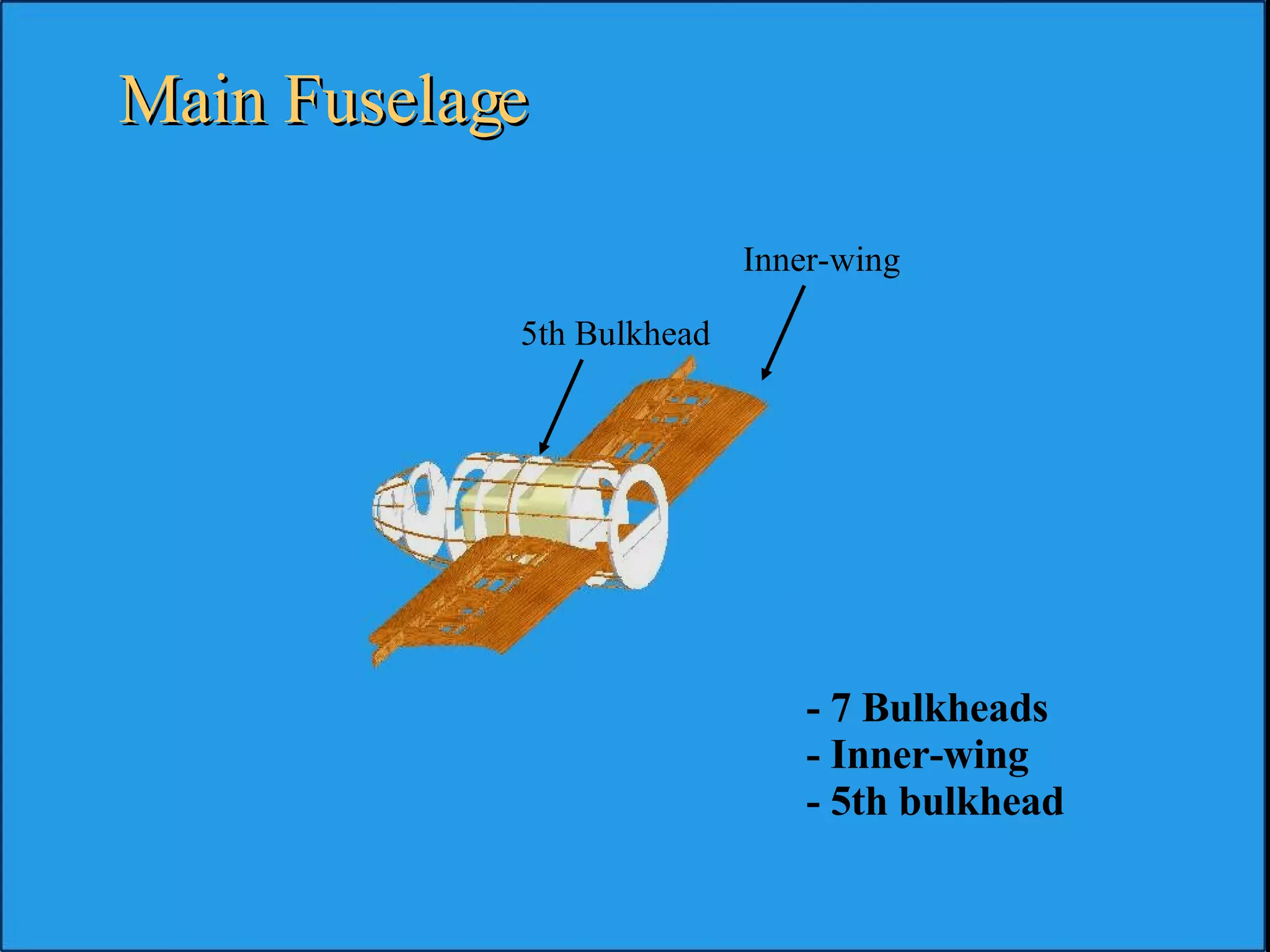
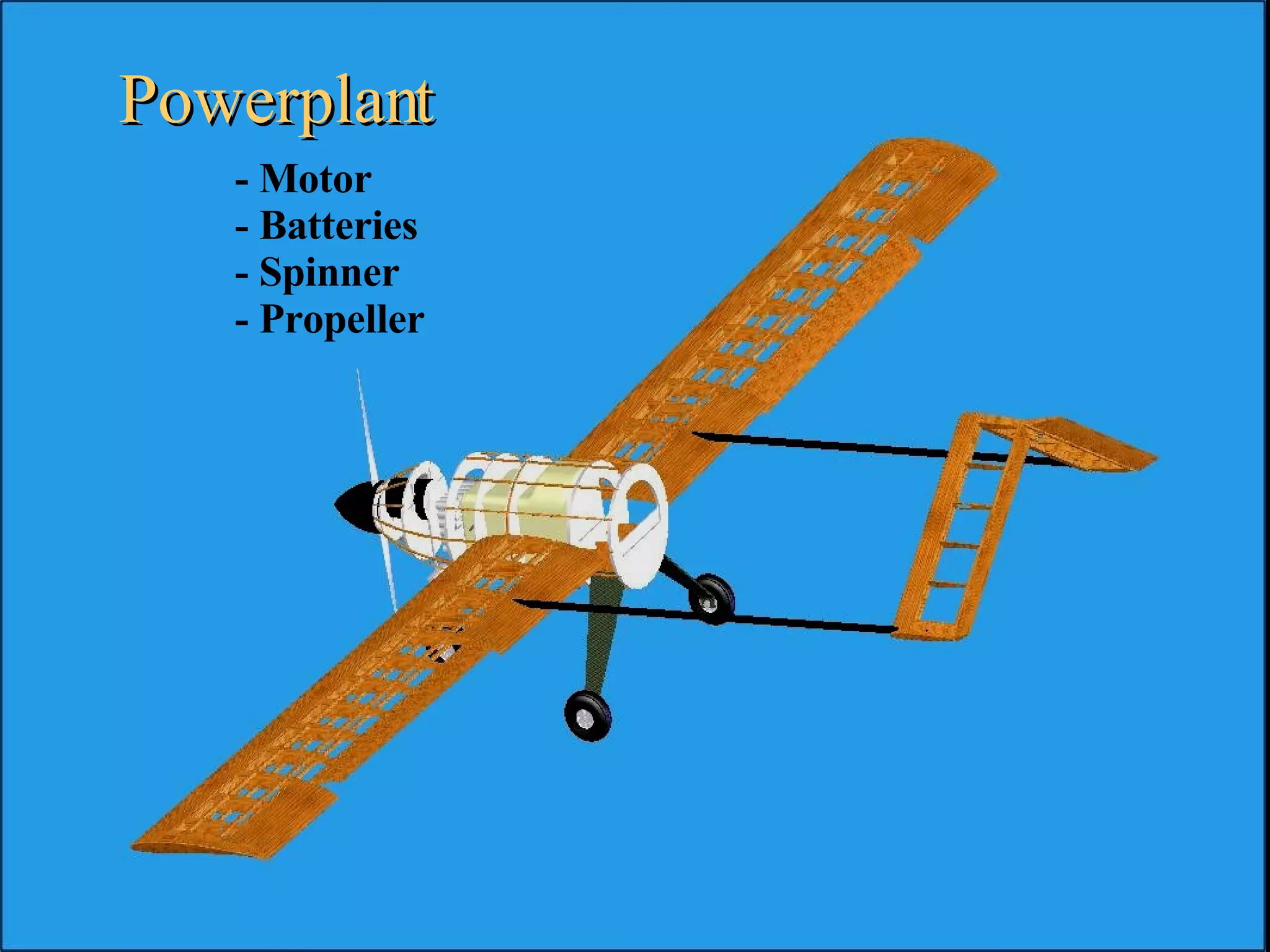
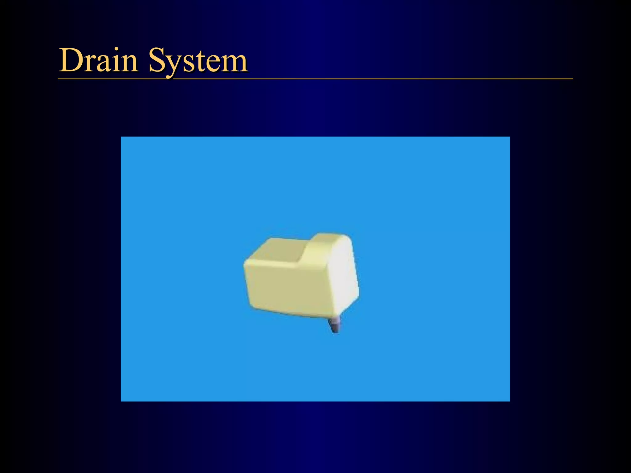
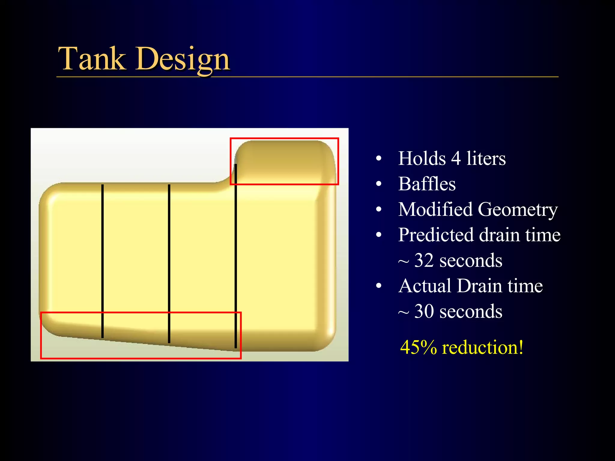
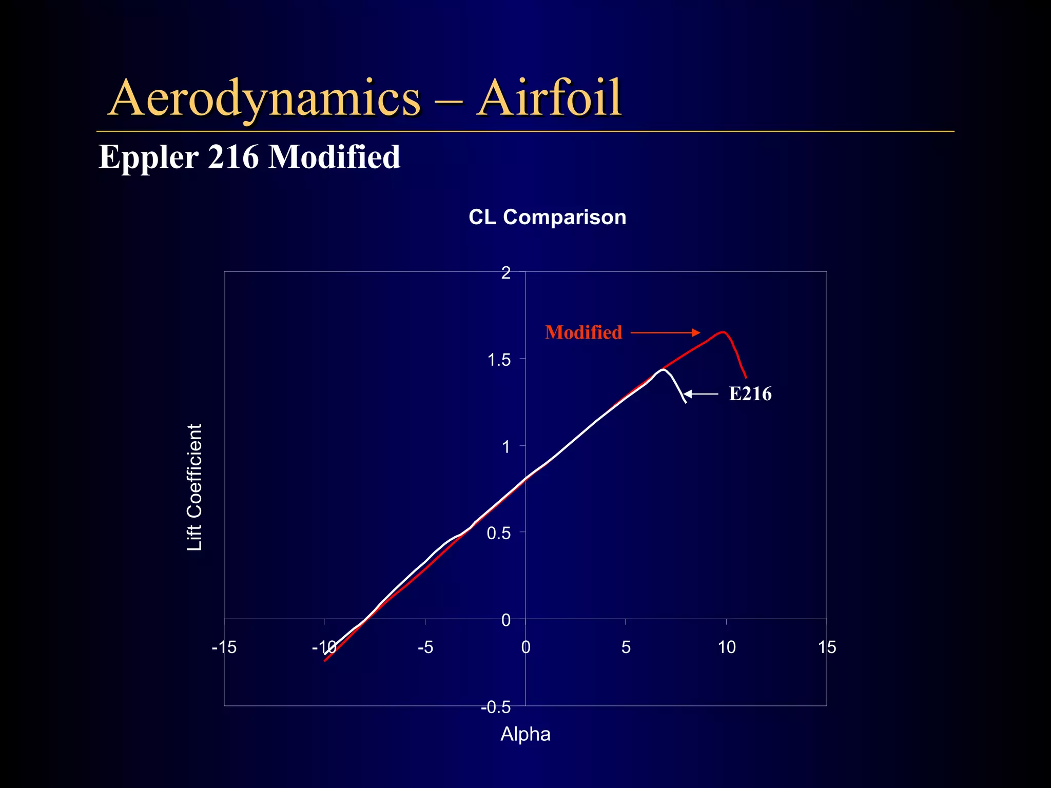
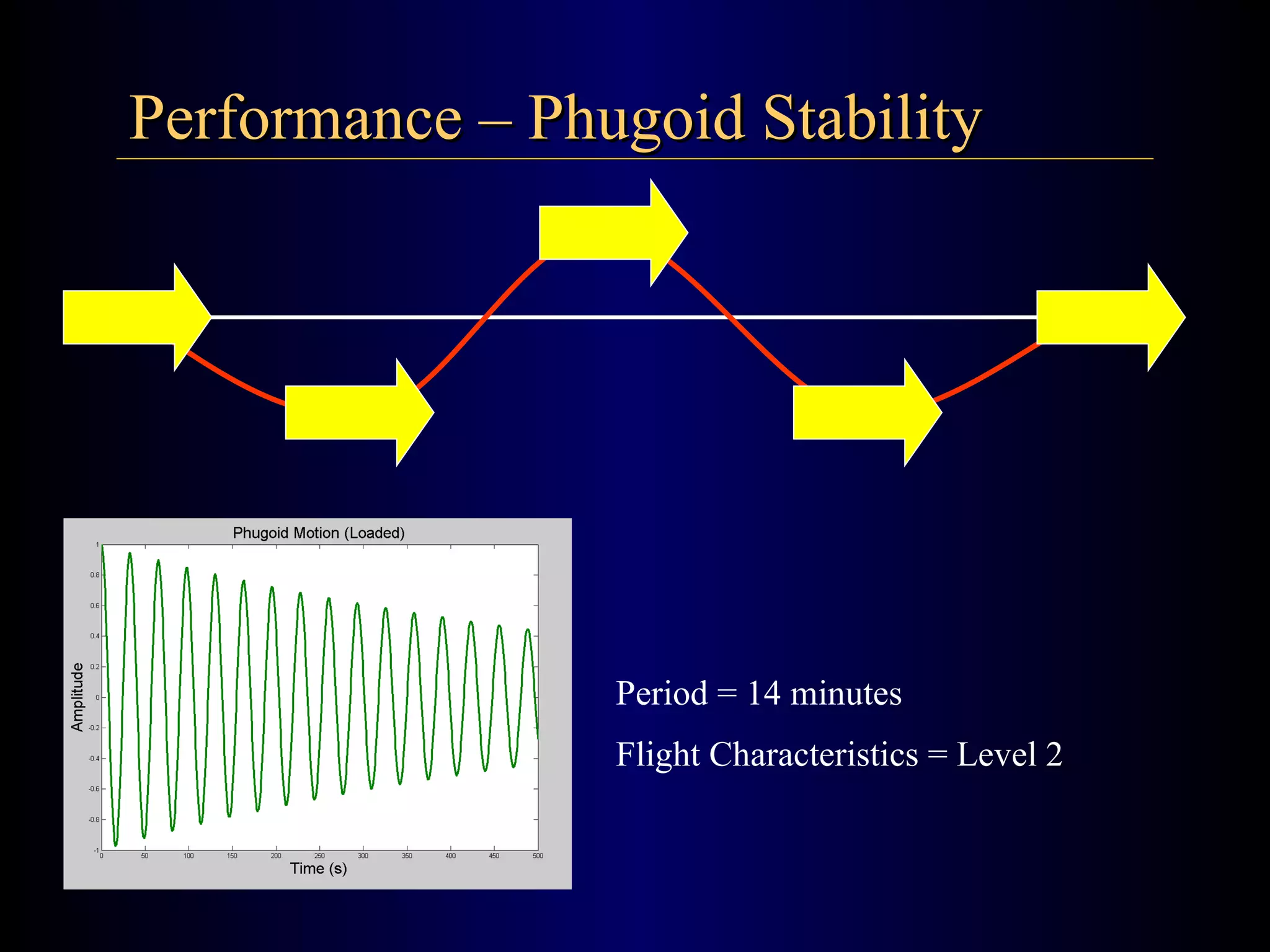
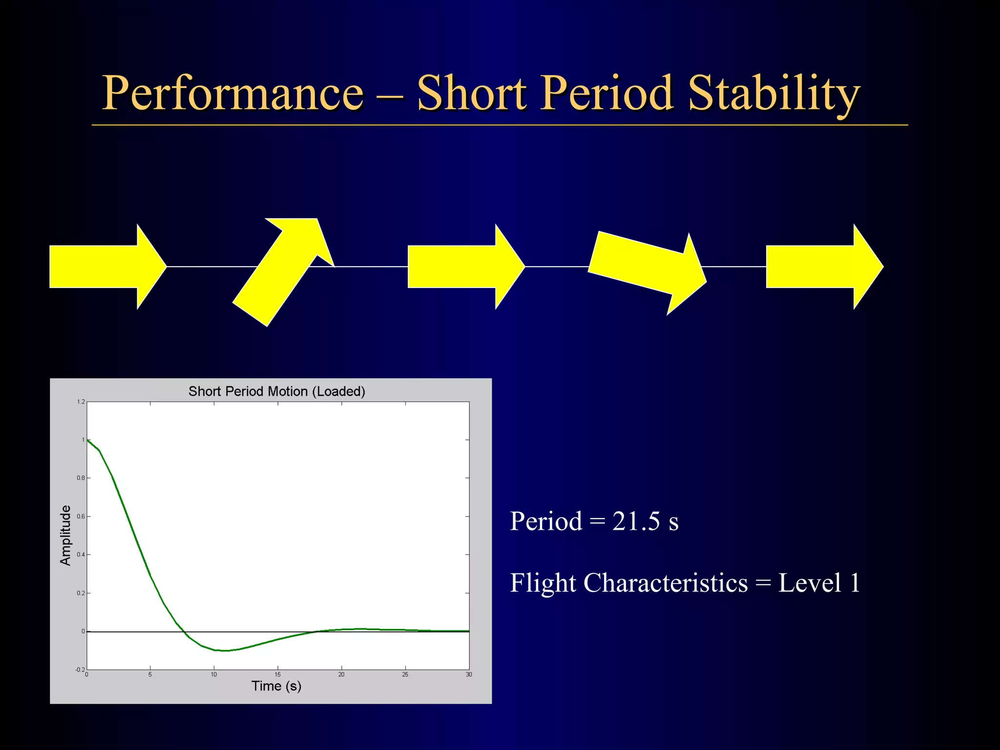
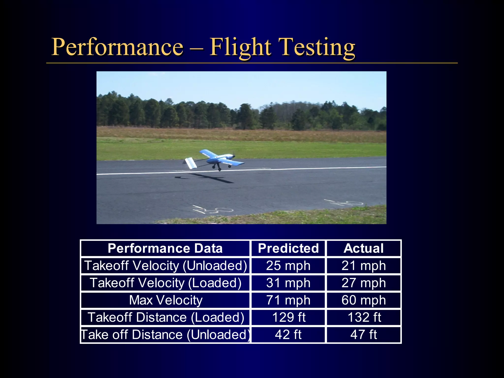
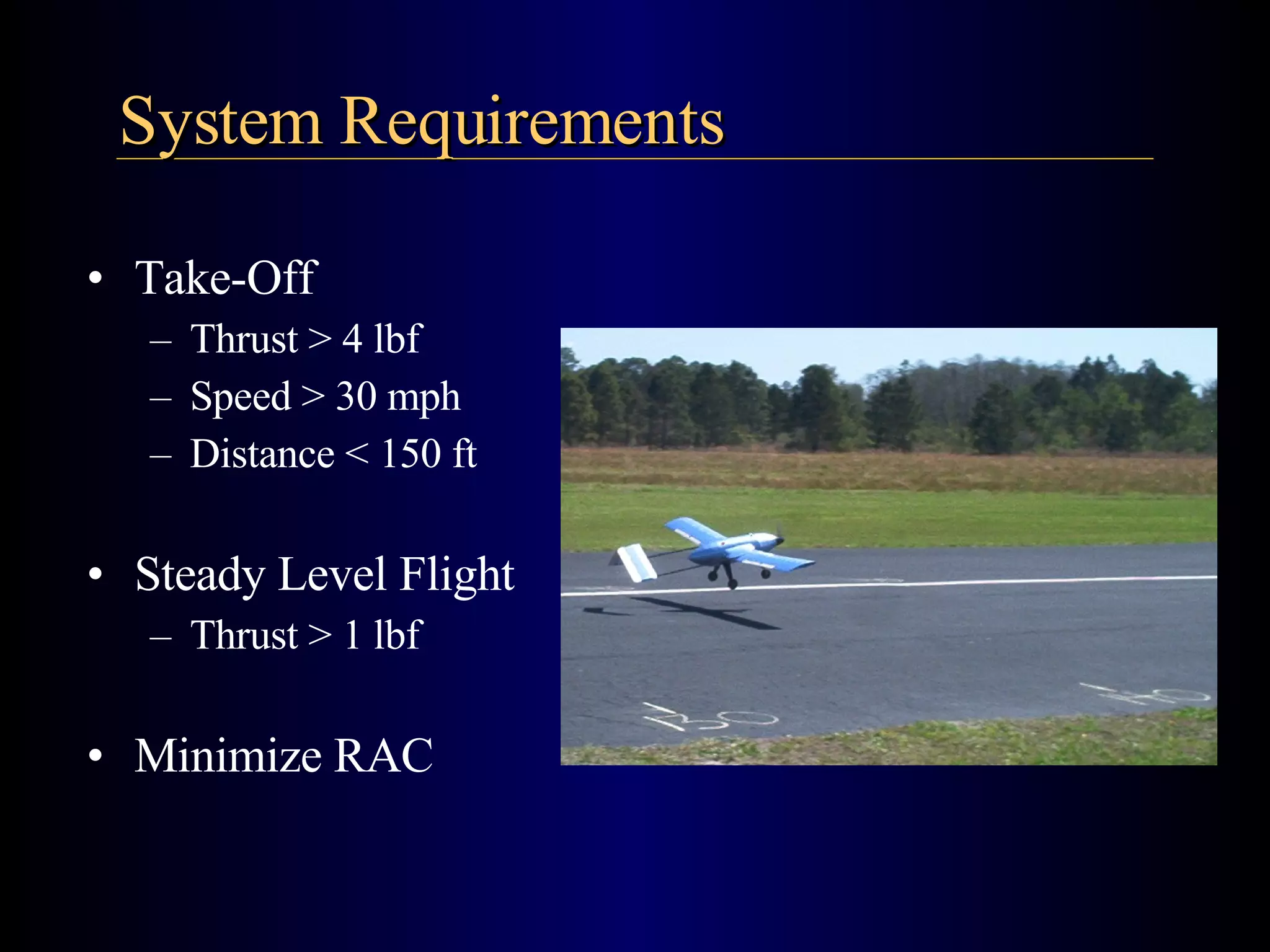
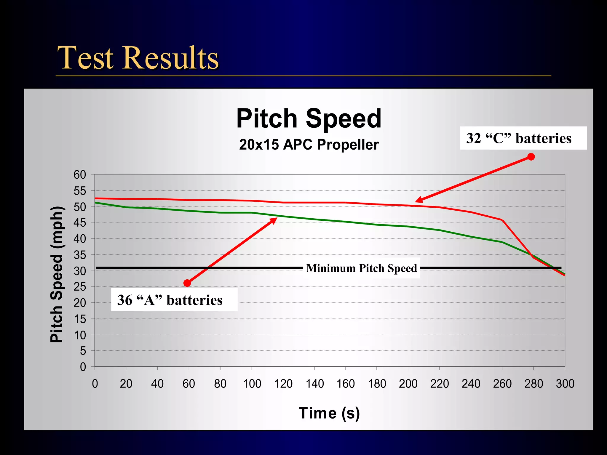
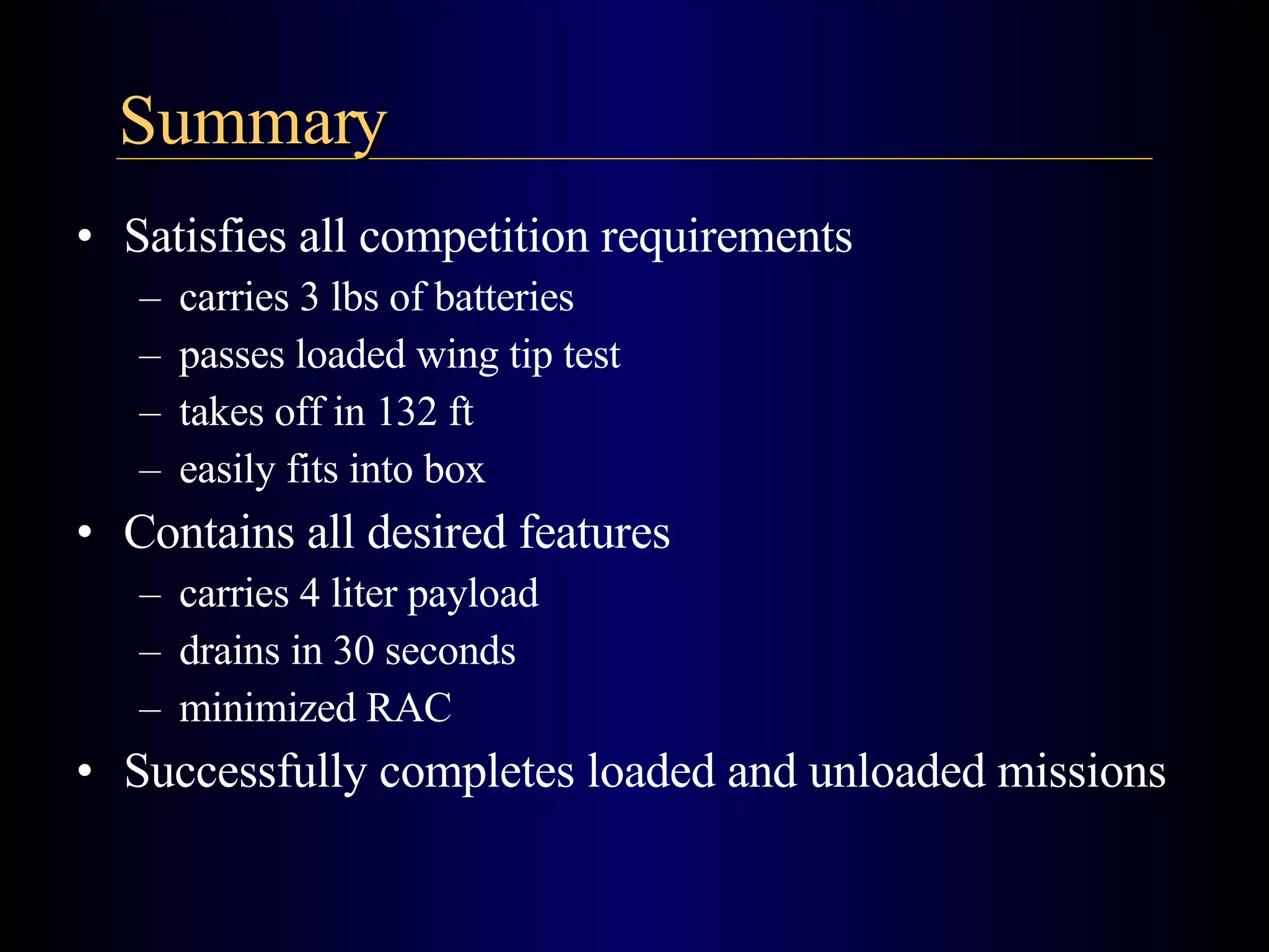
P oseidon’s  F ury Kristina Morace   *   Jonathan Moore   *   Ryan Holmes University of Central Florida AIAA Student Design Build Fly Electric Airplane
Outline 1. Required and Desired Features 2. General Design Overview 3. Drain and Structural Analysis 4. Aerodynamics and Flight Performance 5. Propulsion System  6. Summary
Aircraft Features Required R/C Electric powered 5 lbs max NiCad batteries 4 liters max payload 0.5" max drain orifice Complete 2 missions Pass wing tip tests 4' x 2' x 1' box Desired Carry 4 liters Drain Time ~ 30 sec Lift capacity ~ 25 lb Flight Stability Battery weight ~ 3 lb High pitch speed Low RAC
Rated Aircraft Cost RAC = (300*MEW + 1500*REP + 20*MFHR)/1000   where:  MEW = Empty Weight   REP = Battery Weight   MFHR = Component Summation Total Score =  Written Report * Flight Score   RAC
- Wing span = 9.5 ft - Length = 5 ft - Height = 28 in Aircraft Overview
Drain System - Custom 4 liter tank - Custom ball valve
Main Fuselage - 7 Bulkheads - Inner-wing - 5th bulkhead 5th Bulkhead Inner-wing
Landing Gear - Tricycle Configuration - Carbon Fiber - Detachable
Twin Booms - Carbon Fiber - Detachable
Wing Sections - Secure booms - Bolt to inner wing - Detachable
Inverted V-tail - Pins into booms - Detachable
Powerplant - Motor - Batteries - Spinner - Propeller
Aft Cone - Twists on/off - Access to electronics
 
Drain System
Valve Design Good seal Actuate in flight  True ½ inch orifice Manufactured using stereolithography Drain Coefficient Between 0.6 - 1.0 Actual ~ 0.8 Drain time = 55 sec
Holds 4 liters Baffles Modified Geometry Predicted drain time  ~ 32 seconds Actual Drain time ~ 30 seconds 45% reduction! Tank Design
Wing Spar 5th Bulkhead
Laminate ply 2 layers of carbon fiber 4 attach points Built to support full load ~ 20 lbs Wing Spar
Wing Tip Test   Symmetric 10 lb load at tip Max stress = 27.9 ksi Spar Analysis Max Stress = 27.9 ksi
Landing Gear Analysis Aluminum Gear (661-T6) 3g load Max Von Mises 20.6 ksi FOS = 1.9 Weighs 0.75 lbs Carbon Fiber Gear 3g load Max Tensile Stress 22.2 ksi FOS = 2.0 Weighs 0.43 lbs
Aerodynamics and  Flight Performance
Aerodynamics – Goals  Low Reynolds Number (10 5 ) Lift Coefficient > 1.2 Lift to Drag Ratio > 5 Low Camber Low RAC
Aerodynamics –Test Verification Predicted Test
Aerodynamics – Airfoil Exceeds Needs  C L,max = 1.4 ( L / D ) max  = 22 Problem Thickness to Chord Ratio Too Small Design: 10.4% Need: 12.5% Eppler 216
Aerodynamics – Airfoil Eppler 216 Modified Modified E216
Aerodynamics – Airfoil Eppler 216 Modified
Aerodynamics – Wing 9.5 ’ 10.5 ” AC = 25% of Chord CG = 25% of Chord
Aerodynamics – Empennage Inverted “V” Configuration Pro-verse Yaw Characteristics Aircraft Score Rewards Actual Path Ideal Turn
Aerodynamics – Empennage  Twin Boom Configuration No Ground Strike Robust and Modular Inverted “V” Configuration Pro-verse Yaw Characteristics Aircraft Score Rewards
Aerodynamics – Empennage 28” 7.5” Angle Between Panels = 110 deg.
Flight Performance The Difference:  Longitudinal Stability
Performance – Phugoid Stability Period = 14 minutes Flight Characteristics = Level 2
Performance – Short Period Stability Period = 21.5 s Flight Characteristics = Level 1
Performance – Stability  1 st  Flight resulted in a “5” Poor Roll control from Adverse Yaw Aileron Differential Added Poor Ground Handling Corrected Steering Control Pilot Rating (Cooper-Harper Scale) Remaining Flights are a “1”
Performance – Flight Testing
Propulsion System
Nomenclature System Requirements Predicting Outputs Testing System Integration Safety Features Propulsion System
Energy Density Nomenclature Sanyo 1700 mA-hr “ A” size Ni-Cad battery Sanyo 2400 mA-hr “ C” size Ni-Cad battery Rated Aircraft Cost (RAC) Rated Engine Power (REP) Manufacturer's Empty Weight (MEW) 3 lb 36 cells 5 lb 32 cells
Take-Off Thrust > 4 lbf Speed > 30 mph Distance < 150 ft Steady Level Flight Thrust > 1 lbf Minimize RAC System Requirements
ThrustHP Calculator Software Inputs Propeller Diameter Pitch RPM Outputs Pitch Speed Static Thrust Predicting Outputs Diameter Pitch RPM Pitch Speed Static Thrust
Testing Schematic Multimeter (Voltage) Multimeter (Current) External Power Source Radio Transmitter Spring Scale Current Divider Speed Controller Stroboscope Battery Pack Cobalt 60 Motor (Geared)
Testing Thrust Sled Spring Scale Drawer Glides Motor Mount
Test Results Minimum Thrust 32 “C” batteries 36 “A” batteries
Test Results 32 “C” batteries Minimum Pitch Speed 36 “A” batteries
33% reduction in MEW and REP First 3 minutes 6 lbf Static Thrust 47 mph Pitch Speed Propulsion Results Summary Meets Design Requirements
Propulsion Integration
Kill Switches 40 Amp Fuse PCM Receiver Air Scoops Propulsion Safety Features Forward Scoops Nose Compartment Air Flow Motor Battery Pack Bulkheads Aft
Satisfies all competition requirements carries 3 lbs of batteries passes loaded wing tip test takes off in 132 ft easily fits into box Contains all desired features carries 4 liter payload drains in 30 seconds minimized RAC Successfully completes loaded and unloaded missions Summary
Team Members Michael Denton Craig Daniels Underclassmen Advisor Dr. Eric Petersen Acknowledgements
Questions?

Aiaa Student Design Build Fly Electric Airplane

  • 1.
    P oseidon’s F ury Kristina Morace * Jonathan Moore * Ryan Holmes University of Central Florida AIAA Student Design Build Fly Electric Airplane
  • 2.
    Outline 1. Requiredand Desired Features 2. General Design Overview 3. Drain and Structural Analysis 4. Aerodynamics and Flight Performance 5. Propulsion System 6. Summary
  • 3.
    Aircraft Features RequiredR/C Electric powered 5 lbs max NiCad batteries 4 liters max payload 0.5&quot; max drain orifice Complete 2 missions Pass wing tip tests 4' x 2' x 1' box Desired Carry 4 liters Drain Time ~ 30 sec Lift capacity ~ 25 lb Flight Stability Battery weight ~ 3 lb High pitch speed Low RAC
  • 4.
    Rated Aircraft CostRAC = (300*MEW + 1500*REP + 20*MFHR)/1000 where: MEW = Empty Weight REP = Battery Weight MFHR = Component Summation Total Score = Written Report * Flight Score RAC
  • 5.
    - Wing span= 9.5 ft - Length = 5 ft - Height = 28 in Aircraft Overview
  • 6.
    Drain System -Custom 4 liter tank - Custom ball valve
  • 7.
    Main Fuselage -7 Bulkheads - Inner-wing - 5th bulkhead 5th Bulkhead Inner-wing
  • 8.
    Landing Gear -Tricycle Configuration - Carbon Fiber - Detachable
  • 9.
    Twin Booms -Carbon Fiber - Detachable
  • 10.
    Wing Sections -Secure booms - Bolt to inner wing - Detachable
  • 11.
    Inverted V-tail -Pins into booms - Detachable
  • 12.
    Powerplant - Motor- Batteries - Spinner - Propeller
  • 13.
    Aft Cone -Twists on/off - Access to electronics
  • 14.
  • 15.
  • 16.
    Valve Design Goodseal Actuate in flight True ½ inch orifice Manufactured using stereolithography Drain Coefficient Between 0.6 - 1.0 Actual ~ 0.8 Drain time = 55 sec
  • 17.
    Holds 4 litersBaffles Modified Geometry Predicted drain time ~ 32 seconds Actual Drain time ~ 30 seconds 45% reduction! Tank Design
  • 18.
    Wing Spar 5thBulkhead
  • 19.
    Laminate ply 2layers of carbon fiber 4 attach points Built to support full load ~ 20 lbs Wing Spar
  • 20.
    Wing Tip Test Symmetric 10 lb load at tip Max stress = 27.9 ksi Spar Analysis Max Stress = 27.9 ksi
  • 21.
    Landing Gear AnalysisAluminum Gear (661-T6) 3g load Max Von Mises 20.6 ksi FOS = 1.9 Weighs 0.75 lbs Carbon Fiber Gear 3g load Max Tensile Stress 22.2 ksi FOS = 2.0 Weighs 0.43 lbs
  • 22.
    Aerodynamics and Flight Performance
  • 23.
    Aerodynamics – Goals Low Reynolds Number (10 5 ) Lift Coefficient > 1.2 Lift to Drag Ratio > 5 Low Camber Low RAC
  • 24.
  • 25.
    Aerodynamics – AirfoilExceeds Needs C L,max = 1.4 ( L / D ) max = 22 Problem Thickness to Chord Ratio Too Small Design: 10.4% Need: 12.5% Eppler 216
  • 26.
    Aerodynamics – AirfoilEppler 216 Modified Modified E216
  • 27.
    Aerodynamics – AirfoilEppler 216 Modified
  • 28.
    Aerodynamics – Wing9.5 ’ 10.5 ” AC = 25% of Chord CG = 25% of Chord
  • 29.
    Aerodynamics – EmpennageInverted “V” Configuration Pro-verse Yaw Characteristics Aircraft Score Rewards Actual Path Ideal Turn
  • 30.
    Aerodynamics – Empennage Twin Boom Configuration No Ground Strike Robust and Modular Inverted “V” Configuration Pro-verse Yaw Characteristics Aircraft Score Rewards
  • 31.
    Aerodynamics – Empennage28” 7.5” Angle Between Panels = 110 deg.
  • 32.
    Flight Performance TheDifference: Longitudinal Stability
  • 33.
    Performance – PhugoidStability Period = 14 minutes Flight Characteristics = Level 2
  • 34.
    Performance – ShortPeriod Stability Period = 21.5 s Flight Characteristics = Level 1
  • 35.
    Performance – Stability 1 st Flight resulted in a “5” Poor Roll control from Adverse Yaw Aileron Differential Added Poor Ground Handling Corrected Steering Control Pilot Rating (Cooper-Harper Scale) Remaining Flights are a “1”
  • 36.
  • 37.
  • 38.
  • 39.
  • 40.
    Nomenclature System RequirementsPredicting Outputs Testing System Integration Safety Features Propulsion System
  • 41.
    Energy Density NomenclatureSanyo 1700 mA-hr “ A” size Ni-Cad battery Sanyo 2400 mA-hr “ C” size Ni-Cad battery Rated Aircraft Cost (RAC) Rated Engine Power (REP) Manufacturer's Empty Weight (MEW) 3 lb 36 cells 5 lb 32 cells
  • 42.
    Take-Off Thrust >4 lbf Speed > 30 mph Distance < 150 ft Steady Level Flight Thrust > 1 lbf Minimize RAC System Requirements
  • 43.
    ThrustHP Calculator SoftwareInputs Propeller Diameter Pitch RPM Outputs Pitch Speed Static Thrust Predicting Outputs Diameter Pitch RPM Pitch Speed Static Thrust
  • 44.
    Testing Schematic Multimeter(Voltage) Multimeter (Current) External Power Source Radio Transmitter Spring Scale Current Divider Speed Controller Stroboscope Battery Pack Cobalt 60 Motor (Geared)
  • 45.
    Testing Thrust SledSpring Scale Drawer Glides Motor Mount
  • 46.
    Test Results MinimumThrust 32 “C” batteries 36 “A” batteries
  • 47.
    Test Results 32“C” batteries Minimum Pitch Speed 36 “A” batteries
  • 48.
    33% reduction inMEW and REP First 3 minutes 6 lbf Static Thrust 47 mph Pitch Speed Propulsion Results Summary Meets Design Requirements
  • 49.
  • 50.
    Kill Switches 40Amp Fuse PCM Receiver Air Scoops Propulsion Safety Features Forward Scoops Nose Compartment Air Flow Motor Battery Pack Bulkheads Aft
  • 51.
    Satisfies all competitionrequirements carries 3 lbs of batteries passes loaded wing tip test takes off in 132 ft easily fits into box Contains all desired features carries 4 liter payload drains in 30 seconds minimized RAC Successfully completes loaded and unloaded missions Summary
  • 52.
    Team Members MichaelDenton Craig Daniels Underclassmen Advisor Dr. Eric Petersen Acknowledgements
  • 53.