Downloaded 21 times

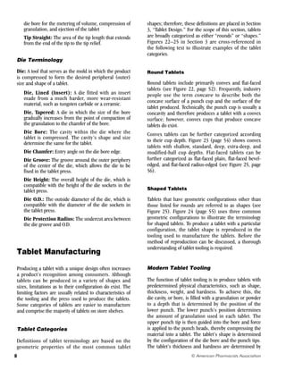
![9
© American Pharmacists Association
the amount of compression force applied to the punch
heads, whereas its weight is determined by the amount
of granulation loaded into the die before compression.
The basic design of tablet punches and dies used in
rotary tablet presses has changed very little since
these presses were first marketed in the late 1800s.
Only minor changes, such as refinements to the head
and tip radius, tighter tolerances, and higher surface
finishes, have been made. In the U.S. tablet industry,
three types of punches and three types of dies are used
predominantly in production presses to produce large
quantities of tablets for market distribution.
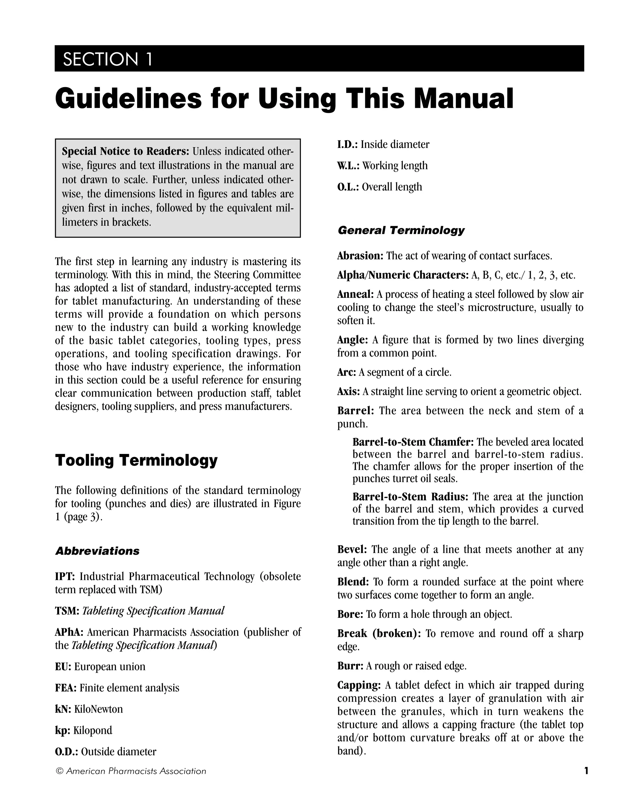
Punches
Punches are classified according to their overall length,
barrel diameter, and the O.D. of the punch head. These
dimensions, as well as the other specifications for tablet
tooling, are nominal: that is, each dimension has a
specified measurement, but its actual measurement
after the tool is produced may vary from its specification.
The allowable variance from a nominal dimension,
called its tolerance range, is discussed later in this
section under “Tooling Specifications.”
The punches most commonly used in production
presses are the B-type and D-type punches (see Figure
2, page 6). B2-type punches are used predominantly in
a few older models of presses that are no longer being
manufactured. During the research stage of a new tablet
design, F-type punches and dies (not pictured) and a
single-station laboratory press are used to determine
the approximate amount of compression force and
granulation needed to produce a tablet with the desired
physical characteristics.
B-Type Punches have a reference overall length of
5.250 inches [133.35 millimeters] and a head O.D. of
1 inch [25.40 millimeters]. These dimensions are the
same for the upper and lower punches. Although the
barrel diameter of a B-type punch is often said to be 3/4
inch [19.05 millimeters], the specified barrel diameter
for the upper—and now the lower—punch is 0.7480
inch [19.00 millimeters].
B2-Type Punches usually have a barrel diameter of 3/4
inch [19.05 millimeters]. Table 8 (pages 44–49) lists
barrel diameters of B2-type punches for specific press
models). This punch has a head O.D. of 1 inch [25.40
millimeters]; however, the overall lengths of the upper
and lower punches differ. The upper punch is 5.250
inches [133.35 millimeters] long, whereas the lower
punch is 3.562 inches [90.475 millimeters] long.
D-Type Punches have the same reference overall
length as B-type punches (5.250 inches [133.35
millimeters]), but the head O.D. of D-type punches
is 1.250 inches [31.75 millimeters]. Again, D-type
punches are often said to have a barrel diameter of 1
inch [25.40 millimeters]; however, the specified barrel
diameter for the upper—and now the lower—punch is
0.9980 inch [25.35 millimeters].
Dies
Dies are classified according to their outside diameters
(see Figure 2, page 6).
The 0.945 Die, as the name indicates, has an O.D. of
0.945 inch [24.00 millimeters]. This size die can be
used with B- and B2-type punches. The die is commonly
referred to as a “BB die.”
The 1.1875 Die, sometimes referred to as the “1 3/16
die,” has an O.D. of 1.1875 inches [30.16 millimeters]
and also can be used with B- and B2-type punches. This
die is commonly referred to as a “B die.”
The “D” Die, which has an O.D. of 1.500 inches [38.10
millimeters], is used with D-type punches.
Comparison of Shaped and Round Tooling
Not surprisingly, punches and dies used to manufacture
round tablets are often called “round tooling,” and
punches and dies used to manufacture shaped tablets
are called “shaped tooling.” After the geometric
configuration of a tablet has been determined by the
designer, the desired configuration is reproduced in the
punch tips and die bores.
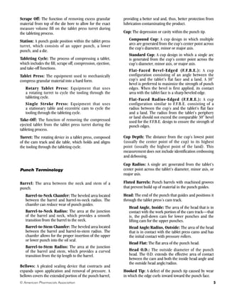
The upper punch for a shaped tablet has a device
called a key that is inserted into a slot in the barrel and
projects above the barrel’s surface (see Figure 1, page
3). The key prevents the punch from rotating as it is
lifted vertically from the die bore so that the punch can
re-enter the die bore at the proper alignment. Because
round configurations are usually unaffected by rotation
of the upper punches, round punches seldom require
a key. However, if a round lower punch is embossed,
a key is sometimes used to prevent punch rotation
and possible distortion of the embossing during tablet
ejection.
Regardless of the tablet shape and the type of tooling
used, the basic press operations are the same.](https://image.slidesharecdn.com/tabletingspecificationsmanua-220127183126/85/Tableting-specifications-manual-9-320.jpg)
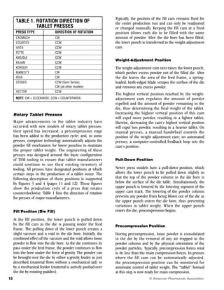
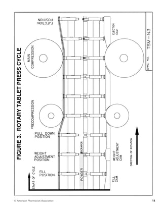
![Main Compression Position
The main compression step gives a tablet its final
characteristics. The final tablet thickness is determined
by the distance between the punch rollers, which
determines the distance between the punch tips. Again,
in some presses, the main compression position can be
monitored for automatic weight control.
Tablet Ejection and Take-Off Position
Before reaching the full ejection position, the upper
punch is lifted out of the die bore while the lower punch
is being pushed up by the ejection cam, thereby pushing
the tablet out of the die. At the full ejection position, a
tablet take-off bar located above the die table guides the
tablet off the table.
The successful completion of each stage of tablet
production depends on how well the tablet tools
work with each other and within the tablet press.
Making sure that tooling and presses conform to TSM
specifications can eliminate many production problems.
Understanding specification drawings is critical in
determining if a tool conforms to TSM specifications.
Tooling Specifications
A tool that conforms to specifications has been
machined to meet specific dimensions within a
designated range called a tolerance range. Dimensions
have been specified for all components of the punches
and dies shown in Figure 1 (page 3). The specifications
drawings for standard punches and dies (Figures 8–11
and 14–16; pages 25–28, 31–33) list these dimensions
first in inches, followed by the equivalent millimeters
placed in brackets. For specifications of radii, an “R”
follows the measurement. If the specification is a
reference dimension, the abbreviation “REF.” follows the
measurement. An explanation of reference dimensions
follows the discussions of tolerances and clearances—
two other dimensional specifications that affect the
proper manufacturing and operation of tablet tooling.
Clearances
If tablet tools are to work properly, there must
be enough space between interacting parts to allow
them to function without making forced contact. This
working space is called clearance. For example, punch
tips must be allowed to enter and leave the die bore
without making forced contact with the die bore wall.
The amount of clearance between interacting parts is
affected by the tolerance range of tooling dimensions.
Tolerances
Producing tooling that match specifications exactly
would be accomplished only at great expense to tooling
manufacturers and ultimately to the companies that
purchase the tooling. For that reason, tolerances, or
allowable deviations, have been established for tooling
specifications. These permissible deviations from
specified dimensions, established in cooperation with
leading tooling and press manufacturers, ensure that
tools can be purchased at a reasonable price and that
they will operate properly in the press to produce good-
quality tablets.
Specifically, a tolerance is given as a range with an upper
limit that determines how much a dimension can be
exceeded and a lower limit that determines how much
a dimension can be reduced. For example, a tooling
dimension that has the specification 1 1/32 [26.19
millimeters] inches ±1/32 inch [0.794 millimeter]
can vary from a high value of 1 1/16 inches [26.99
millimeters] to a low value of 1 inch [25.40 millimeters]
and still be considered to meet specifications.
The tolerance range for a particular specification
immediately follows the dimensional value. The range is
given either as a number preceded by a plus and minus
sign (±) or a set of numbers, one of which is preceded
by a plus sign, the other by a minus sign. If a tolerance
range is not listed next to the dimensional value, the
appropriate tolerances can be found in the block located
in the lower right corner of each specification drawing.
For dimensions given as a fraction, the appropriate
tolerance range is the value labeled as “fractional.” The
same rule applies to dimensions given as decimals and
angles.
The tolerance block also lists the acceptable tolerances
for concentricity of die bores, punch tips, and punch
heads. Concentricity refers to the placement of one
tooling element in the center of another larger element
(i.e., the two tooling elements share the same axis).
The tolerance is given as a T.I.R., or total indicator
reading. Indicator readings measure the form or
location of one surface with respect to another. The
surface relationships of concern here are the die bore to
the O.D.; the punch head to the barrel; and the punch
tip to the barrel. The instrument used to measure
concentricity, called a comparator, has a readout
dial that indicates any deviations in concentricity as
measured by a pointer attached to the dial. The T.I.R. is
the difference between the highest and lowest readings
13
© American Pharmacists Association](https://image.slidesharecdn.com/tabletingspecificationsmanua-220127183126/85/Tableting-specifications-manual-13-320.jpg)
![recorded during one complete rotation of a punch or
die.
Reference Dimension
A reference dimension is derived from, or is the result
of, other toleranced dimensions that are machined
first. For example, the die groove diameter for a 0.945-
inch [24.00 millimeters] die is given as a reference
value of 27/32 inch [21.43 millimeters] ±.015 inch
[.381 millimeter] (see Figure 14, page 31). When
making this die, the die groove width (1/4 inch [6.35
millimeters] ±.015 inch [.381 millimeter]) and the
protection radius (3/16 inch [4.76 millimeters] ±.015
inch [.381 millimeter]) are machined, or “worked to,”
first. When these dimensions have been achieved within
their specified tolerance ranges, the resultant die groove
diameter should fall near its reference dimension.
Comparison of U.S. and International
Tooling Specifications
Presently, there are two major “standards” of tooling
on the international market: the U.S. TSM and the
EuroStandard. Figure 21, (page 50) shows the TSM flat-
head (angled) punch and the EU19, which has a domed
punch head. Besides the illustrated head configurations,
the most significant differences in punch specifications
are those for overall punch length and inner head angle.
Also shown for the two standards of B-type tools are the
correlating differences in die specifications.
As noted on Figures 8–11 (pages 25-28), domed heads
are preferred for new TSM punches. A large number
of flat-head TSM punches currently are being used
for existing products; these punches will continue
to be available. Figures 6 and 7 (pages 23 and 24)
give detailed illustrations of the dimensional and
configurational differences of flat-head and domed
punch heads. Flat-head punches have an outside head
angle, whereas domed heads have a radius. Domed
heads, which were developed by European tooling
manufacturers, increase the dwell time during the tablet
compression stage.
Standardization—Its Purpose
and Advantages
Since the first edition of the Tableting Specification
Manual was published almost a quarter of a century
ago, many U.S. tablet press manufacturers have
voluntarily redesigned their presses to conform with
the specifications. International press manufacturers
also are realizing the economic advantages of making
their presses compatible with TSM tooling. Tablet
manufacturers, especially those with international
production facilities, have compelling reasons for
preferring presses that meet TSM standards.
Advantages of Standardized Tooling
Standardizing tablet tooling offers the following
economic and procedural advantages:
• A uniform quality of tooling can be achieved.
• Tooling suppliers can produce tooling more economi-
cally by standardizing their fabrication equipment and
manufacturing procedures, and by producing batch
quantities of frequently ordered tooling.
• Tooling suppliers can fulfill orders faster by carrying
an inventory of standard sizes of round tooling.
• Procedures for purchasing tooling can be simplified.
• Tablet manufacturers can use tooling interchangeably
in presses purchased from different manufacturers.
• Tablet manufacturers can reduce their tooling inven-
tory.
• Tablet manufacturers can use standard inspection
equipment and validation procedures.
• Multinational pharmaceutical companies can inter-
change tools and discuss tooling technicalities on the
same level.
• Press manufacturers can be sure that their machines
will perform well with standard TSM tooling.
Problems of Nonconformance to
Specifications
Using tools that do not conform to dimensional
specifications can affect tablet quality, press
performance, and tablet production rate. Non-
conformance of tooling to specifications also can (1)
reduce the life of punches, (2) impair the efficient
operation of machinery, and (3) cause severe damage to
tools and presses.
The remaining sections of this manual provide the
necessary information to determine whether a new tool
conforms to TSM specifications. The reader also will find
detailed guidelines on tablet design, standard operating
procedures for procuring and inspecting tooling, and
step-by-step instructions for maintaining tools—an
important function in protecting tooling and presses.
© American Pharmacists Association
14](https://image.slidesharecdn.com/tabletingspecificationsmanua-220127183126/85/Tableting-specifications-manual-14-320.jpg)

This document provides definitions for standard terminology used in tablet manufacturing. It summarizes terminology related to tooling (punches and dies), tablet presses, and specific components of punches. It is intended to establish a common language for clear communication between all parties involved in tablet production. Key terms defined include cup, land, barrel, stem, tip, working length, overall length, neck, head, key, oil seals, clearance, and more. Understanding this terminology provides a foundation of knowledge about basic tablet categories, tooling, press operations, and tooling specifications.


