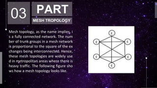
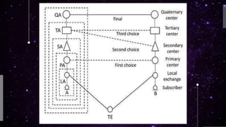
Public switched telephone network (PSTN) or the plain old telephone system (POTS) is perhaps the most stupendous telecommunication network in existence today. There are over 400 million telephone connections over 60,000 telephone exchanges the world over. The length of telephone wire-pairs buried underground exceeds a billion kilometers. A un feature of the telephone network is that every picce of equipment, technique or procedure which has evolved in the last 100 years from a number of different giant corporations, is capable of working with each other. Compa this with the fact that it is almost impossible to interface the first IBM computer with its own latest system. The coormous complexity of the telephone network is managed by using a hierarchical structure, worldwide standardisation, and decentralisation of administration, operation and maintenance.
2. 01 PART
ABSTRACT
Public switched telephone network (PSTN) or the plain old telephone system
(POTS) is perhaps the most stupendous telecommunication network in existe
nce today. There are over 400 million telephone connections over 60,000 tele
phone exchanges the world over. The length of telephone wire-pairs buried u
nderground exceeds a billion kilometers. A un feature of the telephone netwo
rk is that every picce of equipment, technique or procedure which has evolve
d in the last 100 years from a number of different giant corporations, is capabl
e of working with each other. Compa this with the fact that it is almost impossi
ble to interface the first IBM computer with its own latest system. The coormo
us complexity of the telephone network is managed by using a hierarchical st
ructure, worldwide standardisation, and decentralisation of administration, op
eration and maintenance.
3. 02 PART
INTRODUCTION
Telephone networks require some form of interconnection of switching excha
nge to route traffic effectively and economically. Exchanges are Interconnect
ed by groups of trunk lines, usually known as trunk groups that Traffic in one
direction. The interconnectivity of calls between different areas having differe
nt exchanges is done with the help of Trunk lines between the exchanges. T
he group of trunk lines that are used to interconnect different exchanges are
called the Trunk Groups. Two trunk groups are required between any two ex
change. In the process of interconnecting exchanges, there are three basic to
pologies, such as :
1. Mesh Topology
2. Star Topology
3. Hierarchical
4. 03 PART
MESH TROPOLOGY
Mesh topology, as the name implies, i
s a fully connected network. The num
ber of trunk groups in a mesh network
is proportional to the square of the ex
changes being interconnected. Hence,
these mesh topologies are widely use
d in metropolitan areas where there is
heavy traffic. The following figure sho
ws how a mesh topology looks like.
5. 04 PART
STAR TROPOLOGY
Star topology is connected in the sha
pe of a star, which utilizes an interme
diate exchange called a tandem exch
ange through which all other exchang
es communicate. The figure given bel
ow shows the model of a star network
. The star network is used when traffic
levels are comparatively low. Many st
ar networks can be used by interconn
ecting through additional tandem exch
ange, leading to a two-level star netw
ork as shown in the following figure.
6. 05 PART
HIERARCHICAL
The hierarchical topology is used to handle heavy traffic with minimal number of tru
nk groups. The traffic flows through the Final route which is the highest level of hier
archy. If the traffic intensity between any pair of exchanges is high, direct trunk rout
es may be established between them as indicated by dashed lines in the figure given
below. These direct trunk routes are High Usage routes. Wherever these high usage
routes exist, the traffic flows through them. Here, the overflown traffic is routed alo
ng the hierarchical path. No overflow traffic is permitted from the final route. . A 5-L
evel switching hierarchy is recommended by CCITT as shown in Figure. In a strictly hi
erarchical network, traffic from subscriber A to subscriber B and vice versa flows thr
ough the highest level of hierarchy. In Figure, the first choice routing for traffic betw
een subscribers A and B is via the high usage route across the primary centres. The s
econd and the third choice routes and the final route are also indicated in Figure. A
hierarchical system of routing leads to simplified switch design.
7.
8. To decide the routing on a particular connection
, the following three methods are used −
1. Right-through routing
2. Own-exchange routing
3. Computer-controlled routing
In right through routing the originating exchange determines the complete route
from source to destination. No routing decisions are taken at the intermediate ro
uters. In the absence of a computer, only a predetermined route can be chosen
by the originating exchange. However, there may be more than one predetermin
ed route and the originating node may select one out of these, based on certain
criteria like time of the day, even distribution traffic etc.
Own-exchange routing distributed routing allows alternative routes to chosen at
the intermediate nodes. Thus the strategy is capable of responding to changes in
traffic loads and network configurations. Another advantage of distributed routi
ng is that when new changes are added, modifications required in the switch are
minimal.
9. Computers are used in networks with common channel signalling (C
CS) features. la CCS, there is a separate computer-controlled signalli
ng network. puters in position, a number of sophisticated route sele
ction is data networks. A an be implemented. Computer based routi
ng is a standard feature poor Fault networks.
A strictly hierarchical network suffers from one serious drawback, is i
ts fault tolerance feature. A good network design should maintain co
mmunication, though may be with reduced capability and increased
blockage, even in the event of a failure of one or several links due to
causes as fire, explosion, sabotage and natural disaster.Total breakd
own of the network should never occur unless under calamity. In a h
ierarchical network, as we go higher in the hierarchy, the nodes of e
ach rank become fewer and fewer. A failure of a node or communica
tion links at higher levels might seriously jeopardise communications
.
10. 06 PART
ROUTING POLICIES
This dense connectivity simplifies routing. The routing algorithm is as fol
lows:
i.If a call's source and destination are within a central office, directly con
nect them.
ii. If the call is between central offices within a local exchange carrier, us
e a one-hop path between central offices.
iii. Otherwise send the call to (one of the core(s).
The only major decision is at a toll switch, which chooses either a one-h
op or a two-hop path to a destination switching system.
11. 07 PART
CONCLUTIONS
Thus Switching hierarchy helps in an effective switching exchan
ge. In a hierarchical network, as we go higher in the hierarchy,
the nodes of each rank become fewer and fewer. Alternative r
outing paths and redundant nodes have to be provided for in h
igher levels. The current tendency is to reduce the number of l
evels in the hierarchy, and fully interconnect the high level nod
es to provide a large number of alternative routes. It is expecte
d that the future national networks may be built with only thre
e levels of hierarchy.
12. 08 PART
REFERANCES
1. Switching Systems and Networks by Thiagarajan Viswanathan
2. www.tutorialspoint.com
3. www.wikipedia.org
4. Telecommuication Switching Systems and Networks by Thiagarajan
Viswanathan
5. www.tutorialspoint.com
6. www.wikipedia.org