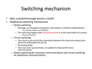
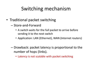
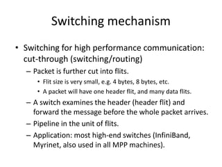
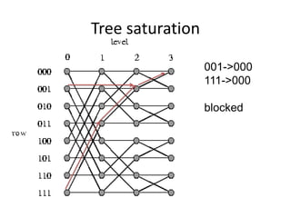
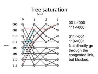
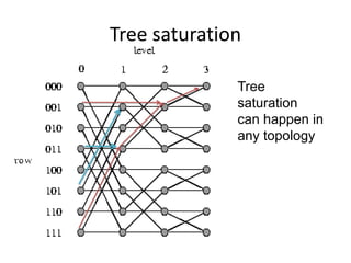
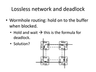
Switching, routing, and flow
control in interconnection
networks
Switching mechanism
• How a packet/message passes a switch
• Traditional switching mechanisms
– Packet switching
• Messages are chopped into packets, each packet is switched independently.
– E.g. Ethernet packet: 64-1500 bytes.
• The switching happens after the whole packet is in the input buffer of a switch.
– Store-and-forward
– Circuit switching
• The circuit is set up first (the connection between the input and output ports
alone the whole path are set up).
• No routing delay
• Too much start-up overheads, no suitable for high performance
communication.
– Packet switching for computer communications and circuit switching
for telephone communications.
Switching mechanism
• Traditional packet switching
– Store-and-Forward
• A switch waits for the full packet to arrive before
sending it to the next switch
• Application: LAN (Ethernet), WAN (Internet routers)
– Drawback: packet latency is proportional to the
number of hops (links).
• Latency is not scalable with packet switching
Switching mechanism
• Switching for high performance communication:
cut-through (switching/routing)
– Packet is further cut into flits.
• Flit size is very small, e.g. 4 bytes, 8 bytes, etc.
• A packet will have one header flit, and many data flits.
– A switch examines the header (header flit) and
forward the message before the whole packet arrives.
– Pipeline in the unit of flits.
– Application: most high-end switches (InfiniBand,
Myrinet, also used in all MPP machines).
Store-and-forward vs. cut-through
• Time = h (n/b + D) Time = n/b + D h
• D is the overhead for preparing to send one flit. The
latency is almost independent of h with cut-through
switching
– Crucial for latency scalability.
Cut-through routing variation
• Cut through routing: when the header of a message is blocked, the whole message
will continue until it is buffered in the blocked router.
– Need to be able to buffer multiple packets
– High buffer requirement in routers
– Eventually, when all buffers are full, the sender will stop sending.
• Wormhole routing
– Cut through routing with buffer for only one flit for each channel
– Minimum buffer requirement
– Each channel has the flow control mechanism.
– when the header is blocked, the message stop moving (the message is buffed in a distributed
manner, occupying buffers in multiple routers).
Contention and link level flow
control
• Two messages try to use the same outgoing link
– One needs to either buffered or droped.
• Wormhole networks try to block in place: link-level flow control.
– A message may occupy multiple links.
– Cut through routing has the same effect when more data are in the
network.
• This kind of networks are also call lossless networks.
– No packet is ever dropped by the network.
– Is the Internet lossless? Which one is better, lossy or lossless network?
Lossless network and tree
saturation
• Lossless networks have very different congestion
behavior from lossy networks such as the
Internet
– In a lossy networks, congestion is limited to a small
region.
– In a lossless network with cut-through or wormhole
routing, congestion will spread to the whole network.
• Messages that do not use the congested link may also be
blocked.
• This is known as tree saturation.
• The congested link is the root of the tree.
Tree saturation
001->000
111->000
blocked
Tree saturation
001->000
111->000
011->001
110->001
Not directly go
through the
congested link,
but blocked.
Tree saturation
Tree
saturation
can happen in
any topology
Lossless network and deadlock
• Wormhole routing: hold on to the buffer
when blocked.
• Hold and wait  this is the formula for
deadlock.
• Solution?
Virtual channels
• A logical channel can be realized with one
buffer and the related flow control
mechanism.
– At one time, one message use the link.
• We can allow multiple messages to share the
link by having multiple virtual channels:
– Each virtual channel has one buffer with the
related flow control mechanism.
– The switch can use some scheduling
algorithm to select flits in different buffer for
forwarding.
– With virtual channel, the train slows down,
but not stops when there is network
contention.
• Virtual channels increase resource sharing
and alleviate to the deadlock problem.
Routing
• Routing algorithms: determine the path from the
source to the desintation
• Properties of routing algorithm:
– Deterministic: routes are determined by source and
destination pair, but other states (e.g. traffic)
– Adaptive: routes are influenced by traffic along the
way.
– Minimal: only selects shortest path.
– Deadlock free: no traffic pattern can lead to a
deadlock situation.
Routing mechanism
• Source routing: message include a list of
intermediate nodes (or ports) toward the
destination. Intermediate routers just lookup and
forward.
• Destination based routing: message only includes
the destination address. Intermediate routers use
the address to compute the output port (e.g. dest
addr as an index to the forwarding table).
– Deterministic: always follow the same path
– Adaptive: pick different paths to avoid congestion
– Randomized: pick between several good paths.
Routing algorithms
• Regular topology
– Dimension order routing with k-ary n-cube
• Ring, mesh, torus, hypercube
• Resolve the address differences in each dimension one
after another
– Tree routing (no routing issue)
– Fat-tree?
• Irregular topology
– Shortest path (like the Internet)
Routing on regular topology
examples
Irregular topology
• Mostly shortest path based.
– How to make sure there is no deadlock?
Deadlock free routing
• Make sure that the loop can never occur
– Put constraints on how paths can be used to route traffic.
– Use infinite virtual channels.
• Deadlock free routing example:
– Up/down routing
• Select a root node and build a spanning tree
• Links are classified as up links or down links
– Up links: from lower level to upper level
– Down links: from upper level to lower level
– Link between nodes in the same level: up/down based on node number
• Path: all up link, all down link, a sequence of up links followed by a
sequence of down links
– No up link can follow a down link.
– Why deadlock free?
– Can we have disconnected nodes?
Deadlock free routing
• Is X-Y routing on mesh deadlock free?
• How about adaptive routing on mesh
that always use the shortest paths?
Network interface design issue
• The network requirement for a typical high performance
computing user
– In-order message delivery
– Reliable delivery
• Error control
• Flow control
– Deadlock free
• Typical network hardware features
– Arbitrary delivery order (adaptive/multipath routing)
– Finite buffering
– Limited fault handling
• Where should the user level functions be realized?
– Network hardware? Network systems? Or a
hardware/systems/software approach?
• Where should these functions be realized?
– How does the Internet realize these functions?
• No deadlock issue
• Reliability/flow control/in-order delivery are done at the TCP
layer?
• The network layer (IP) provides best effort service.
– IP is done in the software as well.
– Drawbacks:
• Too many layers of software
• Users need to go through the OS to access the communication
hardware (system calls can cause context switching).
• Where should these functions be realized?
– High performance networking
• Most functionality below the network layer are done by
the hardware (or almost hardware)
– This provide the APIs for network transactions
• If there is mis-match between what the network
provides and what users want, a software messaging
layer is created to bridge the gaps.
Messaging Layer
• Bridge between the hardware functionality and the
user communication requirement
– Typical network hardware features
• Arbitrary delivery order (adaptive/multipath routing)
• Finite buffering
• Limited fault handling
– Typical user communication requirement
• In-order delivery
• End-to-end flow control
• Reliable transmission
Messaging Layer
Communication cost
• Communication cost = hardware cost + software
cost
– Hardware message time: msize/bandwidth
– Software time:
• Buffer management
• End-to-end flow control
• Running protocols
– Which one is dominating?
• Depends on how much the software has to do.
Network software/hardware
interaction -- a case study
• A case study on the communication
performance issues on CM5
– V. Karamcheti and A. A. Chien, “Software
Overhead in Messaging layers: Where does the
time go?” ACM ASPLOS-VI, 1994.
What do we see in the study?
• The mis-match between the user requirement
and network functionality can introduce
significant software overheads (50%-70%).
• Implication?
– Should we focus on hardware or software or
software/hardware co-design?
– Improving routing performance may increase software
cost
• Adaptive routing introduces out of order packets
– Providing low level network feature to applications is
problematic.
Summary
• In the design of the communication system,
holistic understanding must be achieved:
– Focusing on network hardware may not be
sufficient. Software overhead is much larger than
routing time.
• It would be ideal for the network to directly
provide high level services.

lect10_interconnect.ppt

  • 1.
    Switching, routing, andflow control in interconnection networks
  • 2.
    Switching mechanism • Howa packet/message passes a switch • Traditional switching mechanisms – Packet switching • Messages are chopped into packets, each packet is switched independently. – E.g. Ethernet packet: 64-1500 bytes. • The switching happens after the whole packet is in the input buffer of a switch. – Store-and-forward – Circuit switching • The circuit is set up first (the connection between the input and output ports alone the whole path are set up). • No routing delay • Too much start-up overheads, no suitable for high performance communication. – Packet switching for computer communications and circuit switching for telephone communications.
  • 3.
    Switching mechanism • Traditionalpacket switching – Store-and-Forward • A switch waits for the full packet to arrive before sending it to the next switch • Application: LAN (Ethernet), WAN (Internet routers) – Drawback: packet latency is proportional to the number of hops (links). • Latency is not scalable with packet switching
  • 4.
    Switching mechanism • Switchingfor high performance communication: cut-through (switching/routing) – Packet is further cut into flits. • Flit size is very small, e.g. 4 bytes, 8 bytes, etc. • A packet will have one header flit, and many data flits. – A switch examines the header (header flit) and forward the message before the whole packet arrives. – Pipeline in the unit of flits. – Application: most high-end switches (InfiniBand, Myrinet, also used in all MPP machines).
  • 5.
    Store-and-forward vs. cut-through •Time = h (n/b + D) Time = n/b + D h • D is the overhead for preparing to send one flit. The latency is almost independent of h with cut-through switching – Crucial for latency scalability.
  • 6.
    Cut-through routing variation •Cut through routing: when the header of a message is blocked, the whole message will continue until it is buffered in the blocked router. – Need to be able to buffer multiple packets – High buffer requirement in routers – Eventually, when all buffers are full, the sender will stop sending. • Wormhole routing – Cut through routing with buffer for only one flit for each channel – Minimum buffer requirement – Each channel has the flow control mechanism. – when the header is blocked, the message stop moving (the message is buffed in a distributed manner, occupying buffers in multiple routers).
  • 7.
    Contention and linklevel flow control • Two messages try to use the same outgoing link – One needs to either buffered or droped. • Wormhole networks try to block in place: link-level flow control. – A message may occupy multiple links. – Cut through routing has the same effect when more data are in the network. • This kind of networks are also call lossless networks. – No packet is ever dropped by the network. – Is the Internet lossless? Which one is better, lossy or lossless network?
  • 8.
    Lossless network andtree saturation • Lossless networks have very different congestion behavior from lossy networks such as the Internet – In a lossy networks, congestion is limited to a small region. – In a lossless network with cut-through or wormhole routing, congestion will spread to the whole network. • Messages that do not use the congested link may also be blocked. • This is known as tree saturation. • The congested link is the root of the tree.
  • 9.
  • 10.
    Tree saturation 001->000 111->000 011->001 110->001 Not directlygo through the congested link, but blocked.
  • 11.
  • 12.
    Lossless network anddeadlock • Wormhole routing: hold on to the buffer when blocked. • Hold and wait  this is the formula for deadlock. • Solution?
  • 13.
    Virtual channels • Alogical channel can be realized with one buffer and the related flow control mechanism. – At one time, one message use the link. • We can allow multiple messages to share the link by having multiple virtual channels: – Each virtual channel has one buffer with the related flow control mechanism. – The switch can use some scheduling algorithm to select flits in different buffer for forwarding. – With virtual channel, the train slows down, but not stops when there is network contention. • Virtual channels increase resource sharing and alleviate to the deadlock problem.
  • 14.
    Routing • Routing algorithms:determine the path from the source to the desintation • Properties of routing algorithm: – Deterministic: routes are determined by source and destination pair, but other states (e.g. traffic) – Adaptive: routes are influenced by traffic along the way. – Minimal: only selects shortest path. – Deadlock free: no traffic pattern can lead to a deadlock situation.
  • 15.
    Routing mechanism • Sourcerouting: message include a list of intermediate nodes (or ports) toward the destination. Intermediate routers just lookup and forward. • Destination based routing: message only includes the destination address. Intermediate routers use the address to compute the output port (e.g. dest addr as an index to the forwarding table). – Deterministic: always follow the same path – Adaptive: pick different paths to avoid congestion – Randomized: pick between several good paths.
  • 16.
    Routing algorithms • Regulartopology – Dimension order routing with k-ary n-cube • Ring, mesh, torus, hypercube • Resolve the address differences in each dimension one after another – Tree routing (no routing issue) – Fat-tree? • Irregular topology – Shortest path (like the Internet)
  • 17.
    Routing on regulartopology examples
  • 18.
    Irregular topology • Mostlyshortest path based. – How to make sure there is no deadlock?
  • 19.
    Deadlock free routing •Make sure that the loop can never occur – Put constraints on how paths can be used to route traffic. – Use infinite virtual channels. • Deadlock free routing example: – Up/down routing • Select a root node and build a spanning tree • Links are classified as up links or down links – Up links: from lower level to upper level – Down links: from upper level to lower level – Link between nodes in the same level: up/down based on node number • Path: all up link, all down link, a sequence of up links followed by a sequence of down links – No up link can follow a down link. – Why deadlock free? – Can we have disconnected nodes?
  • 20.
    Deadlock free routing •Is X-Y routing on mesh deadlock free? • How about adaptive routing on mesh that always use the shortest paths?
  • 21.
    Network interface designissue • The network requirement for a typical high performance computing user – In-order message delivery – Reliable delivery • Error control • Flow control – Deadlock free • Typical network hardware features – Arbitrary delivery order (adaptive/multipath routing) – Finite buffering – Limited fault handling • Where should the user level functions be realized? – Network hardware? Network systems? Or a hardware/systems/software approach?
  • 22.
    • Where shouldthese functions be realized? – How does the Internet realize these functions? • No deadlock issue • Reliability/flow control/in-order delivery are done at the TCP layer? • The network layer (IP) provides best effort service. – IP is done in the software as well. – Drawbacks: • Too many layers of software • Users need to go through the OS to access the communication hardware (system calls can cause context switching).
  • 23.
    • Where shouldthese functions be realized? – High performance networking • Most functionality below the network layer are done by the hardware (or almost hardware) – This provide the APIs for network transactions • If there is mis-match between what the network provides and what users want, a software messaging layer is created to bridge the gaps.
  • 24.
    Messaging Layer • Bridgebetween the hardware functionality and the user communication requirement – Typical network hardware features • Arbitrary delivery order (adaptive/multipath routing) • Finite buffering • Limited fault handling – Typical user communication requirement • In-order delivery • End-to-end flow control • Reliable transmission
  • 25.
  • 26.
    Communication cost • Communicationcost = hardware cost + software cost – Hardware message time: msize/bandwidth – Software time: • Buffer management • End-to-end flow control • Running protocols – Which one is dominating? • Depends on how much the software has to do.
  • 27.
    Network software/hardware interaction --a case study • A case study on the communication performance issues on CM5 – V. Karamcheti and A. A. Chien, “Software Overhead in Messaging layers: Where does the time go?” ACM ASPLOS-VI, 1994.
  • 28.
    What do wesee in the study? • The mis-match between the user requirement and network functionality can introduce significant software overheads (50%-70%). • Implication? – Should we focus on hardware or software or software/hardware co-design? – Improving routing performance may increase software cost • Adaptive routing introduces out of order packets – Providing low level network feature to applications is problematic.
  • 29.
    Summary • In thedesign of the communication system, holistic understanding must be achieved: – Focusing on network hardware may not be sufficient. Software overhead is much larger than routing time. • It would be ideal for the network to directly provide high level services.