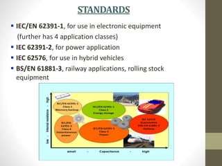
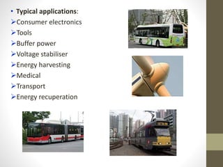
SUPERCAPACITORS
Submitted by:
SACHIN BANSAL
2K13/EL/075
 Introduction
 Evolution
 Principles
 Types
 Construction
 Modelling
 Electrical parameters
 Standards
 Applications
 Market Opportunity
 Conclusion
CONTENTS
INTRODUCTION
Supercapacitor is the generic term for a family of
electrochemical capacitors.
They are electrical energy storage devices with relatively high
energy storage density simultaneously with a high power
density. A specific power of 5,000 W/kg can be reached.
They exhibit very high degree of reversibility in repetitive
charge-discharge cycling. Cycle life over 5,00,000 cycles has
been demonstrated.
They support a broad spectrum of applications (low current for
memory backup, short-term energy storage, burst-mode
power delivery, regenerative braking, etc.)
They have many trade/series names: BestCap, BoostCap,
PseudoCap, EVerCAP, Faradcap, GreenCapUltracapacitor, PAS
Capacitor, EneCapTen, etc.
EVOLUTION
 1957: H. Becker at General Electric develops first patent,
using porous carbon electrodes.
 1966: SOHIO develops another version.
 1970: Donald Boos prepares disc-shaped electrolytic
capacitor.
 1971: SOHIO licenses technology to NEC, who finally
produce first commercially successful double-layer
capacitors, marketing them as ‘supercapacitors.’
 1975-1980: Brian Conway explains the working principles
through extensive research.
 1978: Panasonic markets ‘Goldcaps’.
 1987: ELNA introduces ‘Dynacaps’.
 1982: First low resistance supercapacitor developed by
PRI as “PRI Ultracapacitor”.
 1992: US Department of Energy initiates development
program at Maxwell Laboratories.
 1994: David Evans develops first hybrid supercapacitor.
 2007: FDK pioneers lithium-ion capacitors.
 Current manufacturers:
NEC and Panasonic in Japan
Epcos, Cooper and AVX in USA
Cap-XX in Australia
Tavrima in Canada
ESMA in Russia
Ness Capacitor Co. in Korea
Kold Ban is international marketer
PRINCIPLES
 There are 2 electrodes, separated by a separator,
connected by an electrolyte
 Capacitance value is determined by two storage
principles.
I. Double-layer capacitance: electrostatic storage
achieved by charge separation in a Helmholtz double
layer at the electrode-electrolyte interface.
II. Pseudocapacitance: Faradaic electrochemical storage with
electron charge transfer achieved by surface redox
reactions
 Both principles contribute to the total capacitance, their
ratio depends upon the electrode design & the electrolyte
composition
 The 2 electrodes form a series circuit of two individual capacitors
C1 and C2, so, total capacitance is given by .
 For symmetric capacitors, C1 = C2 = C, so, Ctotal = (0.5) C
 For asymmetric capacitors, C1 << C2, so, Ctotal ≈ C1
TYPES
 Different types of supercapacitors, based on the type of
electrode are as follows.
I. Electrochemical double-layer capacitors (EDLCs):
 Have activated carbon electrodes or derivatives
 No charge-transfer, non Faradaic
 Advantages:
 Higher energy density than conventional capacitors,
comparable power densities, greater cyclability
 Disadvantage:
 Cannot match energy density of mid-level batteries
II. Pseudocapacitors:
 Have metal oxide or conducting polymer electrodes
 Ions diffuse into pores, undergo fast, reversible surface
reactions
 Advantage:
Higher energy density & capacitance than EDLCs
 Disadvantages:
Lower power density than EDLCs, limited life cycle,
expensive electrode material
III. Hybrid Capacitors:
 combine the advantages & mitigate the disadvantages of
the first 2 types
 3 types of electrodes: composite, asymmetric, battery-
type
 Advantages:
Most flexible performance, high energy and power
density without sacrifices in cycling stability
 Disadvantages:
Relatively new and unproven, more research required
CONSTRUCTION
• A supercapacitor cell consists of 2 electrodes, a separator,
and an electrolyte
I. Electrodes:
 Made of metallic collector and, of an active material
 Applied as a paste or powder on metal foils
 Smaller pore size increases capacitance and energy
density but also increases ESR and decreases power
density
II. Electrolytes:
 Provide electrical connection between electrodes
 Should be chemically inert, non-corrosive, less viscous
 Determine operating temperature range, voltage, ESR,
capacitance
 Organic electrolytes give higher energy density, but lower
power density
 Aqueous electrolytes have higher power density, conductivity
III. Separators:
 Ion-permeable membrane, allowing charge transfer but
forbidding electronic contact between the electrodes
 Should be porous to ions, chemically inert
 Examples: PAN films, woven glass fibres
• The construction is rolled/folded to cylindrical/rectangular
shape, stacked in Al can, impregnated with electrolyte that
enters electrode pores
• The housing is hermetically sealed to ensure stable bahaviour
C
1
C
2
C
3
C
4
C
5
+
--
Ultracapacitor stack:
MODELLING
• A first order approximation of EDLC behaviour is a circuit
consisting of ESR and EPR or Rleakage
• A more accurate model presents a circuit with cascaded RC
elements, containing immediate, delayed and long-term
branches, and Rlea
• A treatment of the capacitance in porous electrodes results in
each pore being modelled as a transmission line.
• The transmission line models a distributed double-layer
capacitance and a distributed electrolyte resistance that extends
into the depth of the pore.
ELECTRICALPARAMETERS
I. Capacitance:
 DC capacitance is measured using the formula:
 AC capacitance varies greatly with frequency and is
measured using the formula:
 Discharge current is calculated using the standards given
for different application conditions.
II. Operating voltage:
 Vrated- max. DC voltage within specified temp. range,
includes safety margin for electrolyte breakdown voltage
Applications require values more than Vrated, so, series
connection is required, for which balancing is also needed
III. Internal resistance:
 DC resistance is calculated using the formula:
 This is not same as ESR(rated value).
 It is time-dependent & affects charge/discharge currents
and times.
IV. Current load and cycle stability:
 Much higher than for rechargeable batteries
 Internal heat generated:
 Lower current load increases life, number of cycles
 For “peak-power current”, robust design is required
V. Energy density and power density:
 Energy,
 Effective realized energy,
 Maximum theoretical power,
 Realistic effective power,
 In these terms, supercapacitors bridge the gap b/w
batteries & classical capacitors.
 Ragone chart shows relation b/w energy density & power
density, used to compare performance
VI. Lifetime:
 Depends on capacitor temperature & voltage applied
 Higher temp. causes faster evaporation of electrolyte
 Acc. to standards, capacitance reduction of 30% &
resistance increase of 4 times is a “wear-out failure”
 Manufacturers specify it as “tested time(hrs)/max. temp.”,
using endurance test
 For every 10 ̊C rise in temp., estimated life doubles.
 Development of gas depends on the voltage.
 No general formula relates voltage to lifetime.
VII. Self-discharge:
 Caused because of surface irregularities in electrodes
 Known as leakage current
 Depends on capacitance, voltage, temperature &
chemical stability of electrode/electrolyte combination
 It is low at room temp.,specified in hours, days or weeks
VIII.Polarity:
 In theory, supercapacitors have no polarity, but
recommended practice is to maintain the prod. polarity
 Polarities differ for capacitors and batteries.
 A –ve bar in the insulating sleeve identifies the cathode.
STANDARDS
 IEC/EN 62391-1, for use in electronic equipment
(further has 4 application classes)
 IEC 62391-2, for power application
 IEC 62576, for use in hybrid vehicles
 BS/EN 61881-3, railway applications, rolling stock
equipment
APPLICATIONS
• Time t a supercapacitor can deliver constant current is
given as
• For constant power P, this time is given by
• Potential applications: pulse power systems (defibrillators,
detonators, lasers), load levelling, UPS, quick charge
applications (wireless power tools), high cycle and long life
systems (sensors, metro buses), all-weather applications
• In general, there are 2 domains of application.
I. High power applications, where short time power peaks
are required. Examples: HEVs, starters
II. Low power applications, where batteries have
insufficient lifetime performance. Examples: UPS,
security systems
• Typical applications:
Consumer electronics
Tools
Buffer power
Voltage stabiliser
Energy harvesting
Medical
Transport
Energy recuperation
MARKETOPPORTUNITY
Obstacles to
grow
• Relatively high cost
• Competition with batteries well established on
the market
• Consumer conservatism
Factors to growth
• New market opportunities like HEVs, Smart Grid,
Alternative/Renewable Energy
• Growing ecology restrictions for competitors
• Operation in a wide temperature range
• Good prospects or a combined power supply
$560 mln.
Fig. 5. Annual Sales divided by segments
(Ultracapacitors - A Global Industry and Market
Analysis, Innovative Research and Products , Inc. 2006)
70.8
144.8
111.4
161.489.6
254.4
0
100
200
300
400
500
600
2006 2011
Electronics UPS and power tools Transportation
$272 mln.
World Supercapacitors Market, $ mln.
CONCLUSION
• Supercapacitors may be used wherever high power delivery
or electrical energy storage is required. Hence, numerous
applications are possible.
• Their use allows a complementation of normal batteries. In
combination with batteries, they can improve maximum
instantaneous output power and battery lifetime.
• Major areas of R&D in supercapacitors (future of
supercaps):
Reduction of material impurities (that cause self-discharge)
Improvement in fabrication & packaging methods
Reduction in the ESR to increase power
Optimization of electrolytes & electrodes
Further exploration of hybrid capacitors- the most
promising, but least developed supercap technology
THANK YOU

Supercaps

  • 1.
  • 2.
     Introduction  Evolution Principles  Types  Construction  Modelling  Electrical parameters  Standards  Applications  Market Opportunity  Conclusion CONTENTS
  • 3.
    INTRODUCTION Supercapacitor is thegeneric term for a family of electrochemical capacitors. They are electrical energy storage devices with relatively high energy storage density simultaneously with a high power density. A specific power of 5,000 W/kg can be reached. They exhibit very high degree of reversibility in repetitive charge-discharge cycling. Cycle life over 5,00,000 cycles has been demonstrated. They support a broad spectrum of applications (low current for memory backup, short-term energy storage, burst-mode power delivery, regenerative braking, etc.) They have many trade/series names: BestCap, BoostCap, PseudoCap, EVerCAP, Faradcap, GreenCapUltracapacitor, PAS Capacitor, EneCapTen, etc.
  • 4.
    EVOLUTION  1957: H.Becker at General Electric develops first patent, using porous carbon electrodes.  1966: SOHIO develops another version.  1970: Donald Boos prepares disc-shaped electrolytic capacitor.  1971: SOHIO licenses technology to NEC, who finally produce first commercially successful double-layer capacitors, marketing them as ‘supercapacitors.’  1975-1980: Brian Conway explains the working principles through extensive research.  1978: Panasonic markets ‘Goldcaps’.  1987: ELNA introduces ‘Dynacaps’.
  • 5.
     1982: Firstlow resistance supercapacitor developed by PRI as “PRI Ultracapacitor”.  1992: US Department of Energy initiates development program at Maxwell Laboratories.  1994: David Evans develops first hybrid supercapacitor.  2007: FDK pioneers lithium-ion capacitors.  Current manufacturers: NEC and Panasonic in Japan Epcos, Cooper and AVX in USA Cap-XX in Australia Tavrima in Canada ESMA in Russia Ness Capacitor Co. in Korea Kold Ban is international marketer
  • 6.
    PRINCIPLES  There are2 electrodes, separated by a separator, connected by an electrolyte  Capacitance value is determined by two storage principles. I. Double-layer capacitance: electrostatic storage achieved by charge separation in a Helmholtz double layer at the electrode-electrolyte interface.
  • 7.
    II. Pseudocapacitance: Faradaicelectrochemical storage with electron charge transfer achieved by surface redox reactions  Both principles contribute to the total capacitance, their ratio depends upon the electrode design & the electrolyte composition
  • 8.
     The 2electrodes form a series circuit of two individual capacitors C1 and C2, so, total capacitance is given by .  For symmetric capacitors, C1 = C2 = C, so, Ctotal = (0.5) C  For asymmetric capacitors, C1 << C2, so, Ctotal ≈ C1
  • 9.
    TYPES  Different typesof supercapacitors, based on the type of electrode are as follows. I. Electrochemical double-layer capacitors (EDLCs):  Have activated carbon electrodes or derivatives  No charge-transfer, non Faradaic  Advantages:  Higher energy density than conventional capacitors, comparable power densities, greater cyclability  Disadvantage:  Cannot match energy density of mid-level batteries II. Pseudocapacitors:  Have metal oxide or conducting polymer electrodes  Ions diffuse into pores, undergo fast, reversible surface reactions
  • 10.
     Advantage: Higher energydensity & capacitance than EDLCs  Disadvantages: Lower power density than EDLCs, limited life cycle, expensive electrode material III. Hybrid Capacitors:  combine the advantages & mitigate the disadvantages of the first 2 types  3 types of electrodes: composite, asymmetric, battery- type  Advantages: Most flexible performance, high energy and power density without sacrifices in cycling stability  Disadvantages: Relatively new and unproven, more research required
  • 11.
    CONSTRUCTION • A supercapacitorcell consists of 2 electrodes, a separator, and an electrolyte I. Electrodes:  Made of metallic collector and, of an active material  Applied as a paste or powder on metal foils  Smaller pore size increases capacitance and energy density but also increases ESR and decreases power density II. Electrolytes:  Provide electrical connection between electrodes  Should be chemically inert, non-corrosive, less viscous  Determine operating temperature range, voltage, ESR, capacitance  Organic electrolytes give higher energy density, but lower power density
  • 12.
     Aqueous electrolyteshave higher power density, conductivity III. Separators:  Ion-permeable membrane, allowing charge transfer but forbidding electronic contact between the electrodes  Should be porous to ions, chemically inert  Examples: PAN films, woven glass fibres • The construction is rolled/folded to cylindrical/rectangular shape, stacked in Al can, impregnated with electrolyte that enters electrode pores • The housing is hermetically sealed to ensure stable bahaviour C 1 C 2 C 3 C 4 C 5 + -- Ultracapacitor stack:
  • 13.
    MODELLING • A firstorder approximation of EDLC behaviour is a circuit consisting of ESR and EPR or Rleakage • A more accurate model presents a circuit with cascaded RC elements, containing immediate, delayed and long-term branches, and Rlea
  • 14.
    • A treatmentof the capacitance in porous electrodes results in each pore being modelled as a transmission line. • The transmission line models a distributed double-layer capacitance and a distributed electrolyte resistance that extends into the depth of the pore.
  • 15.
    ELECTRICALPARAMETERS I. Capacitance:  DCcapacitance is measured using the formula:  AC capacitance varies greatly with frequency and is measured using the formula:  Discharge current is calculated using the standards given for different application conditions. II. Operating voltage:  Vrated- max. DC voltage within specified temp. range, includes safety margin for electrolyte breakdown voltage
  • 16.
    Applications require valuesmore than Vrated, so, series connection is required, for which balancing is also needed III. Internal resistance:  DC resistance is calculated using the formula:  This is not same as ESR(rated value).  It is time-dependent & affects charge/discharge currents and times. IV. Current load and cycle stability:  Much higher than for rechargeable batteries  Internal heat generated:  Lower current load increases life, number of cycles  For “peak-power current”, robust design is required
  • 17.
    V. Energy densityand power density:  Energy,  Effective realized energy,  Maximum theoretical power,  Realistic effective power,  In these terms, supercapacitors bridge the gap b/w batteries & classical capacitors.  Ragone chart shows relation b/w energy density & power density, used to compare performance
  • 18.
    VI. Lifetime:  Dependson capacitor temperature & voltage applied  Higher temp. causes faster evaporation of electrolyte  Acc. to standards, capacitance reduction of 30% & resistance increase of 4 times is a “wear-out failure”  Manufacturers specify it as “tested time(hrs)/max. temp.”, using endurance test  For every 10 ̊C rise in temp., estimated life doubles.  Development of gas depends on the voltage.  No general formula relates voltage to lifetime.
  • 19.
    VII. Self-discharge:  Causedbecause of surface irregularities in electrodes  Known as leakage current  Depends on capacitance, voltage, temperature & chemical stability of electrode/electrolyte combination  It is low at room temp.,specified in hours, days or weeks VIII.Polarity:  In theory, supercapacitors have no polarity, but recommended practice is to maintain the prod. polarity  Polarities differ for capacitors and batteries.  A –ve bar in the insulating sleeve identifies the cathode.
  • 20.
    STANDARDS  IEC/EN 62391-1,for use in electronic equipment (further has 4 application classes)  IEC 62391-2, for power application  IEC 62576, for use in hybrid vehicles  BS/EN 61881-3, railway applications, rolling stock equipment
  • 21.
    APPLICATIONS • Time ta supercapacitor can deliver constant current is given as • For constant power P, this time is given by • Potential applications: pulse power systems (defibrillators, detonators, lasers), load levelling, UPS, quick charge applications (wireless power tools), high cycle and long life systems (sensors, metro buses), all-weather applications • In general, there are 2 domains of application. I. High power applications, where short time power peaks are required. Examples: HEVs, starters II. Low power applications, where batteries have insufficient lifetime performance. Examples: UPS, security systems
  • 22.
    • Typical applications: Consumerelectronics Tools Buffer power Voltage stabiliser Energy harvesting Medical Transport Energy recuperation
  • 23.
    MARKETOPPORTUNITY Obstacles to grow • Relativelyhigh cost • Competition with batteries well established on the market • Consumer conservatism Factors to growth • New market opportunities like HEVs, Smart Grid, Alternative/Renewable Energy • Growing ecology restrictions for competitors • Operation in a wide temperature range • Good prospects or a combined power supply $560 mln. Fig. 5. Annual Sales divided by segments (Ultracapacitors - A Global Industry and Market Analysis, Innovative Research and Products , Inc. 2006) 70.8 144.8 111.4 161.489.6 254.4 0 100 200 300 400 500 600 2006 2011 Electronics UPS and power tools Transportation $272 mln. World Supercapacitors Market, $ mln.
  • 24.
    CONCLUSION • Supercapacitors maybe used wherever high power delivery or electrical energy storage is required. Hence, numerous applications are possible. • Their use allows a complementation of normal batteries. In combination with batteries, they can improve maximum instantaneous output power and battery lifetime. • Major areas of R&D in supercapacitors (future of supercaps): Reduction of material impurities (that cause self-discharge) Improvement in fabrication & packaging methods Reduction in the ESR to increase power Optimization of electrolytes & electrodes Further exploration of hybrid capacitors- the most promising, but least developed supercap technology
  • 25.