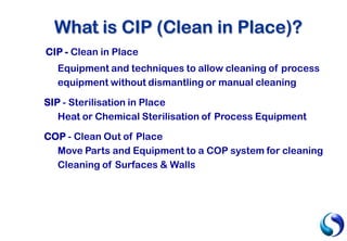
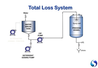
Design for CIP
By
Nicholas Jeffery and Elliott Sutton
Suncombe Ltd
1. What is CIP?
2. Why CIP?
3. Advantages of CIP
4. Cleaning in Place Detail
5. Types of CIP Systems
6. Sterilisation in Place
7. Monitoring
8. Design Consideration
9. Summary
Topics to be Covered
CIP - Clean in Place
Equipment and techniques to allow cleaning of process
equipment without dismantling or manual cleaning
SIP - Sterilisation in Place
Heat or Chemical Sterilisation of Process Equipment
COP - Clean Out of Place
Move Parts and Equipment to a COP system for cleaning
Cleaning of Surfaces & Walls
What is CIP (Clean in Place)?
Reproducible, Repeatable and Controllable Results
Reduction of Cleaning Time
Automatic cycles ensure every item is cleaned every
time
Increased productivity through reduction of down
time
Chemical Handling Reduction
Simple Operation
Why CIP?
Cost and Utility Savings including chemicals, water and
effluent, labour time etc.
Health and Safety
Batch Traceability and Records
Stronger Chemicals and higher temperatures can be
used
More complex processing systems can be used
Environmental Issues and Legislation
Advantages of CIP
1) CIP is superior to any cleaning method
Automated, with parameter monitoring & control
Repeatability  reliability
Human errors eliminated
Eliminate contaminated products
2) Lower operating costs
Reduced labour costs
Cleaning turnaround time reduced
Water / solvents / detergents usage significantly reduced
3) Safety Improvement
Reduced exposure of product to personnel
No equipment dismantling / vessel entry
Eliminates hazardous activities, eg HP water blasting
Why Use CIP
Temperature
Time
Chemical
Mechanical
CIP Variables
Effect on cleaning operation:
Soil Effect
Proteins medium
Fats good
Sugars good
Salts good
Note : Generally a 10°C temperature increase will improve
cleaning efficiency by 50% (above 30°C)
Temperature
Effect on cleaning operation:
1) Turbulence in Piping
Laminar flow Re < 2,300
Transition flow 2,300 < Re < 3,000
Turbulent flow Re > 3,000
Reynolds number, Re = D v r D is pipe internal diameter
µ v is fluid velocity
r is fluid density
µ is fluid viscosity
Note : Normally take velocity to be >2 m/s
 1½” tube at 2 m/s  Re = 78,000TURBULENT FLOW
LAMINAR FLOW
Mechanical
Effect on cleaning operation :
a) Automatic Tank Wash devices
• Fixed Spray Devices
• Self-powered Rotating
• Self-powered Turbine
2) Action in Equipment
PROCESS
VESSEL
Mechanical (continued…)
Effect on cleaning operation:
Soil Water Alkali Acid
Proteins poor good medium
Fats poor good medium
Sugars good -- --
Salts medium medium good
Note : required concentrations depend on soil level,
processes used, working time, temperture, ….
Chemical (Detergent)
Rinsing. In general, the final rinse used for equipment should
use the same quality water as used in the final stage of
manufacture.
Quality of Water used for aqueous cleaning is
critical for performance:
• Chemical properties (pH, hardness, etc.)
• Biological properties (bioburden, endotoxins)
Washing. Most critical is water hardness – effects efficiency
of cleaning of aqueous surfactant solutions.
Pre-Rinsing. Solely for flushing out of residue prior to washing
step. Usually based on practicality of what water is available.
Water Used for Cleaning Process
The duration of each CIP cycle step is to be
optimised according to the main following
parameters :
Type of Process Equipment
Type of Process Carried Out
Duration of Process Run
Cleaning solution temperature
Chemical concentration
Time (Duration)
Step Operation Cleaning
Agent
Temp.
(ºC)
Time
(Min.)
Usage
1 Pre-Rinse Water 20 – 30 2 – 5 To drain
2 Alkali Clean 2% Caustic 70 – 90 5 – 30 Re-circulated
3 Inter-rinse Water 20 – 30 1 – 5 To drain
4 Acid clean 1% Phosphoric 50 – 70 3 – 15 Re-circulated
5 Inter-rinse Water 20 – 30 4 – 10 To drain
6 Sterilant Peracetic Acid 20 – 30 3 – 15 Re-circulated
7 Final Rinse Water 20 – 30 4 – 10 To drain
Typical CIP Programme
Boil Out (Fill / Flood) System
Total Loss
Single Use Recirculation
Re - Use (Recovery)
Multi Channel
Fixed & Mobile Systems
WIP and COP
Types of CIP Systems
Detergent
Water
(Solvent)
Drain
PROCESS
VESSEL
Heat
Advantages
No / Small Capital Investment
Very Small Vessels
Cleans Complicated Mixer Systems
No additional Equipment Need
Solvent based
Disadvantages
High Detergent & Water Usage
Extended Cleaning Times
Health & Safety Considerations
Difficult to Monitor /Validate
Boil Out System (Fill/Flood)
Water
DETERGENT
DOSING PUMP
CIP
PUMP
PROCESS
VESSEL
Spray ball
WATER
BREAK
TANK
DRAIN
ALTERNATIVE
DOSING POSITION
Total Loss System
Advantages
Improved Health & Safety
Simple Installation
Water
DETERGENT
DOSING PUMP
CIP
PUMP
WATER
BREAK
TANK
To
Process
Vessel
Disadvantages
High Detergent & Water Usage
Extended Cleaning Time
Difficult to Monitor / Validate
Total Loss System
Advantages
Flexible System
Lower Cost Installation (than Re-
Use)
Good Economy for Local
System
Small Floor Space
LOW CROSS CONTAMINATION
RISK
Water
DETERGENT
DOSING
PUMP
CIP PUMP
CIP RETURN
PUMP
DRAIN
WATER
BREAK
TANK
Disadvantages
Not Suitable for Large
Centralised Systems
Single Use Recirculation System
Fresh
Water
Detergent
Dosing Pump
CIP
PUMP
CIP RETURN
PUMP
DETERGENT
TANK Drain
Advantages
Good Water / Detergent Usage
Centralised Systems & Controls
Disadvantages
Inflexibility
Higher Equipment & Installation
Costs
CROSS CONTAMINATION RISK FOR
DIS-SIMILAR PRODUCTS OR
RAW/COOKED CONDITION
Re-Use System
Fresh
Water
Detergent
Dosing Pump
CIP PUMP
PROCESS
VESSEL
Spray ball
CIP
RETURN
PUMP
RECOVERED
WATER TANK
DETERGENT
TANK Drain
Re-Use System with Recovered Water Tank
FRESH
WATER
CAUSTIC
SOLUTION
ACID
SOLUTION
REUSED
WATER
ASEPTIC
SOLUTION
1 2 3 4 5
1
2
3
4
1
2
3
4
Multi-Channel Re-Use System
SOLUTION
Vessel
A
Vessel
B
cross-contamination
Multi-Channel System
Re-Use Single Use
Solution Tanks 2 to 5 1 or none
Soln. Temperatures Fixed Adjustable
Soln. Concentrations Fixed Adjustable
Simultaneous
operations
1 to 4
(Multi-channel)
1 only
Flexibility Poor High
Cross contamination High Risk Small Risk
Investment cost Higher Lower
Running Cost Lower Higher
MAIN CRITERIA CLEANING COST CLEANING QUALITY
System Comparisons
Example: 3000 L Storage Vessel, with 100 Lpm Sprayball
1.5% Detergent. 5 min Rinses. 20 min Detergent
SYSTEM WATER DETERGENT
Boil Out System 6500 L 45 L
Total Loss 3000 L 30 L
Single Use 1200 L 3 L
Partial Re-Use 1100 L 2 L
Full Re-Use 600 L 2 L
System Comparisons (continued…)
Re-use System
Typical Pharmacuetical CIP Unit
Reduces Pipework Installation
Limits to size of unit & Capacity
Service Requirements
Heating problems
Ideal for small cleaning duties
Mobile CIP Units
There is no legislative distinction
between Clean In Place (CIP) and
Wash In Place (WIP), however the
general industry view on the
terminology is that CIP means a
totally automatic cleaning
sequence with no manual
involvement, whereas as WIP
includes some manual intervention.
In practical terms CIP requires high
levels of validation, against WIP
which requires less stringent
validation.
Courtesy of Matcon
WIP or CIP?
The introduction of the ATEX
directive to include all components
that are ATEX certified, mechanical
as well as electrical
The problems with component
selection associated with systems
that reside continually in an ATEX
area
Can use aqueous or solvent cleaning
media
ATEX rated spraydevices
Inert atmospheres for spray cleaning
ATEX CIP Considerations
Answer: When it is a COP
Application.
COP or Cleaning Out of Place
is when the equipment is
moved to the cleaning
equipment prior to a CIP
clean
When is a CIP Application not
a CIP Application?
Sterilization is not to be considered as part of
the cleaning process.
Purpose of Sterilization is to destroy any form
of micro-organism.
Chemical Sterilization
- Chlorine, hypochlorite, hydrogen peroxide, ozone,
peracetic acid
Thermal Sterilization
- dry heat, steam, superheated water
SIP (Sterilisation in Place)
Conductivity To Monitor Strength
To Separate Phases
Temperature In Feed Line to Control
In Return Line to Monitor
Flow In Feed & Return to Confirm Rate
Pressure In Feed Line for Spray Device
In Return for Integrity Testing
Time From the Control System
Turbidity In Return Line to Monitor
Monitoring Systems
„Cleanability‟ of components & fittings
used for process installations
Safety breaks & circuit separation
Circuit balancing of CIP circuit
Prevention of „dead legs‟ in process circuits
Surface finish of tanks and piping
Welding techniques
CIP/Process Design
Made of corrosion-resistant and cleanable materials
Must confine the cleaning solution
Must be drainable, with no pockets or ledges
Any corners should be rounded
Gaskets & seals – crevice-free, non-absorbent, non-
reactive, non-porous (FDA-approved elastomers)
Minimum interconnecting fittings in piping
All valves & instruments should be cleanable
Use of hoses should be minimised
Equipment/System to be cleaned…
C IP IN PU T
C IP OU TPU T
C IP IN PU T
C IP IN PU T
C IP IN PU T
C IP OU TPU T
C IP OU TPU T
C IP OU TPU T
Routing Plate
Routing Plate
Circuit
Separation
10 m3/h
15 m3/h
20 m3/h
15 m3/h
CIP INPUT
CIP INPUT
CIP OUTPUT
CIP OUTPUT
Always have a higher output
flow than input flow for CIP
Circuit Balance
CIP INPUT
CIP INPUT
CIP INPUT
CIP INPUT
Always have safe separation
between process and cleaning
Double block
and bleed
Routing Plate
Safety Break
System
CIP INPUT
CIP INPUT
PROCESS
PROCESS
Beware of Dead-legs
in the process and
cleaning circuits
Preventation of
Deadlegs
uncleanable
limit of
cleanability
OK
OK
Best
L = 1 D
L = 3 D
L = 5 D
L = 0 D
Zero dead-leg
valve
Dead-legs
Laminar Flow
(Low Velocity)
Re 2300
Re 3000
- Mechanical Action
Turbulent Flow
(High Velocity)
Ensure sufficient fluid
flow velocities in the
process and cleaning
circuits
Pipework Velocity
Disadvantages
Higher Water Usage
Less Mechanical Action
Less Bounce Back
Longer cleaning times
Advantages
No maintenance
Special Spray Patterns
Easier to Monitor
Less Pump Power
Spray Devices – Fixed
Low Pressure – High Flow
Disadvantages
Higher Pump Power
More Difficult to Monitor
Generally Higher Cost
More Difficult to “Aim” Spray
Higher Maintenance
Advantages
Lower Water Usage
Greater Mechanical Action
Greater Bounce Back
Greater Throw Distances
Slotted
‘Turbodisk’
Jets
Spray Device – Rotating
High Pressure – Low Flow
0 3
0
100
%
roughness
(µm)
0 3
0 (µm)
30
minutes
roughness
TIME TO DESTROY 99,9%
OF MICRO-ORGANISMS
(relative values)
REDUCTION % OF MICRO-ORGANISMS
AFTER A STANDARD CIP CYCLE
(relative values)
Surface Finish
Poor Hand Weld
• Difficult to clean
• Drainage problems
• Corrosion
Orbital Weld
Welding Techniques
Evaluation of Cleaning Risk
CIP Unit Selection (Skid Packages)
Flexibility allowing Customisation
CIP / SIP / Process Interface from start
Incorporate Hygienic Design
Monitoring to Ensure Repeatability
Summary of CIP/SIP
Thank You For
Your Attention
For More Information Contact Suncombe
Tel: +44 (0)20 8443 3454
www.suncombe.com

Suncombe cip overview presentation

  • 1.
    Design for CIP By NicholasJeffery and Elliott Sutton Suncombe Ltd
  • 2.
    1. What isCIP? 2. Why CIP? 3. Advantages of CIP 4. Cleaning in Place Detail 5. Types of CIP Systems 6. Sterilisation in Place 7. Monitoring 8. Design Consideration 9. Summary Topics to be Covered
  • 3.
    CIP - Cleanin Place Equipment and techniques to allow cleaning of process equipment without dismantling or manual cleaning SIP - Sterilisation in Place Heat or Chemical Sterilisation of Process Equipment COP - Clean Out of Place Move Parts and Equipment to a COP system for cleaning Cleaning of Surfaces & Walls What is CIP (Clean in Place)?
  • 4.
    Reproducible, Repeatable andControllable Results Reduction of Cleaning Time Automatic cycles ensure every item is cleaned every time Increased productivity through reduction of down time Chemical Handling Reduction Simple Operation Why CIP?
  • 5.
    Cost and UtilitySavings including chemicals, water and effluent, labour time etc. Health and Safety Batch Traceability and Records Stronger Chemicals and higher temperatures can be used More complex processing systems can be used Environmental Issues and Legislation Advantages of CIP
  • 6.
    1) CIP issuperior to any cleaning method Automated, with parameter monitoring & control Repeatability  reliability Human errors eliminated Eliminate contaminated products 2) Lower operating costs Reduced labour costs Cleaning turnaround time reduced Water / solvents / detergents usage significantly reduced 3) Safety Improvement Reduced exposure of product to personnel No equipment dismantling / vessel entry Eliminates hazardous activities, eg HP water blasting Why Use CIP
  • 7.
  • 8.
    Effect on cleaningoperation: Soil Effect Proteins medium Fats good Sugars good Salts good Note : Generally a 10°C temperature increase will improve cleaning efficiency by 50% (above 30°C) Temperature
  • 9.
    Effect on cleaningoperation: 1) Turbulence in Piping Laminar flow Re < 2,300 Transition flow 2,300 < Re < 3,000 Turbulent flow Re > 3,000 Reynolds number, Re = D v r D is pipe internal diameter µ v is fluid velocity r is fluid density µ is fluid viscosity Note : Normally take velocity to be >2 m/s  1½” tube at 2 m/s  Re = 78,000TURBULENT FLOW LAMINAR FLOW Mechanical
  • 10.
    Effect on cleaningoperation : a) Automatic Tank Wash devices • Fixed Spray Devices • Self-powered Rotating • Self-powered Turbine 2) Action in Equipment PROCESS VESSEL Mechanical (continued…)
  • 11.
    Effect on cleaningoperation: Soil Water Alkali Acid Proteins poor good medium Fats poor good medium Sugars good -- -- Salts medium medium good Note : required concentrations depend on soil level, processes used, working time, temperture, …. Chemical (Detergent)
  • 12.
    Rinsing. In general,the final rinse used for equipment should use the same quality water as used in the final stage of manufacture. Quality of Water used for aqueous cleaning is critical for performance: • Chemical properties (pH, hardness, etc.) • Biological properties (bioburden, endotoxins) Washing. Most critical is water hardness – effects efficiency of cleaning of aqueous surfactant solutions. Pre-Rinsing. Solely for flushing out of residue prior to washing step. Usually based on practicality of what water is available. Water Used for Cleaning Process
  • 13.
    The duration ofeach CIP cycle step is to be optimised according to the main following parameters : Type of Process Equipment Type of Process Carried Out Duration of Process Run Cleaning solution temperature Chemical concentration Time (Duration)
  • 14.
    Step Operation Cleaning Agent Temp. (ºC) Time (Min.) Usage 1Pre-Rinse Water 20 – 30 2 – 5 To drain 2 Alkali Clean 2% Caustic 70 – 90 5 – 30 Re-circulated 3 Inter-rinse Water 20 – 30 1 – 5 To drain 4 Acid clean 1% Phosphoric 50 – 70 3 – 15 Re-circulated 5 Inter-rinse Water 20 – 30 4 – 10 To drain 6 Sterilant Peracetic Acid 20 – 30 3 – 15 Re-circulated 7 Final Rinse Water 20 – 30 4 – 10 To drain Typical CIP Programme
  • 15.
    Boil Out (Fill/ Flood) System Total Loss Single Use Recirculation Re - Use (Recovery) Multi Channel Fixed & Mobile Systems WIP and COP Types of CIP Systems
  • 16.
    Detergent Water (Solvent) Drain PROCESS VESSEL Heat Advantages No / SmallCapital Investment Very Small Vessels Cleans Complicated Mixer Systems No additional Equipment Need Solvent based Disadvantages High Detergent & Water Usage Extended Cleaning Times Health & Safety Considerations Difficult to Monitor /Validate Boil Out System (Fill/Flood)
  • 17.
  • 18.
    Advantages Improved Health &Safety Simple Installation Water DETERGENT DOSING PUMP CIP PUMP WATER BREAK TANK To Process Vessel Disadvantages High Detergent & Water Usage Extended Cleaning Time Difficult to Monitor / Validate Total Loss System
  • 19.
    Advantages Flexible System Lower CostInstallation (than Re- Use) Good Economy for Local System Small Floor Space LOW CROSS CONTAMINATION RISK Water DETERGENT DOSING PUMP CIP PUMP CIP RETURN PUMP DRAIN WATER BREAK TANK Disadvantages Not Suitable for Large Centralised Systems Single Use Recirculation System
  • 20.
    Fresh Water Detergent Dosing Pump CIP PUMP CIP RETURN PUMP DETERGENT TANKDrain Advantages Good Water / Detergent Usage Centralised Systems & Controls Disadvantages Inflexibility Higher Equipment & Installation Costs CROSS CONTAMINATION RISK FOR DIS-SIMILAR PRODUCTS OR RAW/COOKED CONDITION Re-Use System
  • 21.
    Fresh Water Detergent Dosing Pump CIP PUMP PROCESS VESSEL Sprayball CIP RETURN PUMP RECOVERED WATER TANK DETERGENT TANK Drain Re-Use System with Recovered Water Tank
  • 22.
  • 23.
  • 24.
    Re-Use Single Use SolutionTanks 2 to 5 1 or none Soln. Temperatures Fixed Adjustable Soln. Concentrations Fixed Adjustable Simultaneous operations 1 to 4 (Multi-channel) 1 only Flexibility Poor High Cross contamination High Risk Small Risk Investment cost Higher Lower Running Cost Lower Higher MAIN CRITERIA CLEANING COST CLEANING QUALITY System Comparisons
  • 25.
    Example: 3000 LStorage Vessel, with 100 Lpm Sprayball 1.5% Detergent. 5 min Rinses. 20 min Detergent SYSTEM WATER DETERGENT Boil Out System 6500 L 45 L Total Loss 3000 L 30 L Single Use 1200 L 3 L Partial Re-Use 1100 L 2 L Full Re-Use 600 L 2 L System Comparisons (continued…)
  • 26.
  • 27.
    Reduces Pipework Installation Limitsto size of unit & Capacity Service Requirements Heating problems Ideal for small cleaning duties Mobile CIP Units
  • 28.
    There is nolegislative distinction between Clean In Place (CIP) and Wash In Place (WIP), however the general industry view on the terminology is that CIP means a totally automatic cleaning sequence with no manual involvement, whereas as WIP includes some manual intervention. In practical terms CIP requires high levels of validation, against WIP which requires less stringent validation. Courtesy of Matcon WIP or CIP?
  • 29.
    The introduction ofthe ATEX directive to include all components that are ATEX certified, mechanical as well as electrical The problems with component selection associated with systems that reside continually in an ATEX area Can use aqueous or solvent cleaning media ATEX rated spraydevices Inert atmospheres for spray cleaning ATEX CIP Considerations
  • 30.
    Answer: When itis a COP Application. COP or Cleaning Out of Place is when the equipment is moved to the cleaning equipment prior to a CIP clean When is a CIP Application not a CIP Application?
  • 31.
    Sterilization is notto be considered as part of the cleaning process. Purpose of Sterilization is to destroy any form of micro-organism. Chemical Sterilization - Chlorine, hypochlorite, hydrogen peroxide, ozone, peracetic acid Thermal Sterilization - dry heat, steam, superheated water SIP (Sterilisation in Place)
  • 32.
    Conductivity To MonitorStrength To Separate Phases Temperature In Feed Line to Control In Return Line to Monitor Flow In Feed & Return to Confirm Rate Pressure In Feed Line for Spray Device In Return for Integrity Testing Time From the Control System Turbidity In Return Line to Monitor Monitoring Systems
  • 33.
    „Cleanability‟ of components& fittings used for process installations Safety breaks & circuit separation Circuit balancing of CIP circuit Prevention of „dead legs‟ in process circuits Surface finish of tanks and piping Welding techniques CIP/Process Design
  • 34.
    Made of corrosion-resistantand cleanable materials Must confine the cleaning solution Must be drainable, with no pockets or ledges Any corners should be rounded Gaskets & seals – crevice-free, non-absorbent, non- reactive, non-porous (FDA-approved elastomers) Minimum interconnecting fittings in piping All valves & instruments should be cleanable Use of hoses should be minimised Equipment/System to be cleaned…
  • 35.
    C IP INPU T C IP OU TPU T C IP IN PU T C IP IN PU T C IP IN PU T C IP OU TPU T C IP OU TPU T C IP OU TPU T Routing Plate Routing Plate Circuit Separation
  • 36.
    10 m3/h 15 m3/h 20m3/h 15 m3/h CIP INPUT CIP INPUT CIP OUTPUT CIP OUTPUT Always have a higher output flow than input flow for CIP Circuit Balance
  • 37.
    CIP INPUT CIP INPUT CIPINPUT CIP INPUT Always have safe separation between process and cleaning Double block and bleed Routing Plate Safety Break System
  • 38.
    CIP INPUT CIP INPUT PROCESS PROCESS Bewareof Dead-legs in the process and cleaning circuits Preventation of Deadlegs
  • 39.
    uncleanable limit of cleanability OK OK Best L =1 D L = 3 D L = 5 D L = 0 D Zero dead-leg valve Dead-legs
  • 40.
    Laminar Flow (Low Velocity) Re2300 Re 3000 - Mechanical Action Turbulent Flow (High Velocity) Ensure sufficient fluid flow velocities in the process and cleaning circuits Pipework Velocity
  • 41.
    Disadvantages Higher Water Usage LessMechanical Action Less Bounce Back Longer cleaning times Advantages No maintenance Special Spray Patterns Easier to Monitor Less Pump Power Spray Devices – Fixed Low Pressure – High Flow
  • 42.
    Disadvantages Higher Pump Power MoreDifficult to Monitor Generally Higher Cost More Difficult to “Aim” Spray Higher Maintenance Advantages Lower Water Usage Greater Mechanical Action Greater Bounce Back Greater Throw Distances Slotted ‘Turbodisk’ Jets Spray Device – Rotating High Pressure – Low Flow
  • 43.
    0 3 0 100 % roughness (µm) 0 3 0(µm) 30 minutes roughness TIME TO DESTROY 99,9% OF MICRO-ORGANISMS (relative values) REDUCTION % OF MICRO-ORGANISMS AFTER A STANDARD CIP CYCLE (relative values) Surface Finish
  • 44.
    Poor Hand Weld •Difficult to clean • Drainage problems • Corrosion Orbital Weld Welding Techniques
  • 45.
    Evaluation of CleaningRisk CIP Unit Selection (Skid Packages) Flexibility allowing Customisation CIP / SIP / Process Interface from start Incorporate Hygienic Design Monitoring to Ensure Repeatability Summary of CIP/SIP
  • 46.
    Thank You For YourAttention For More Information Contact Suncombe Tel: +44 (0)20 8443 3454 www.suncombe.com