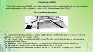
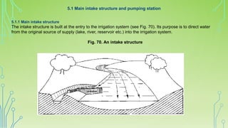
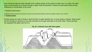
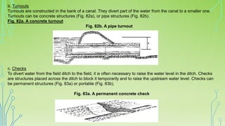
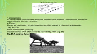
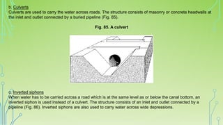
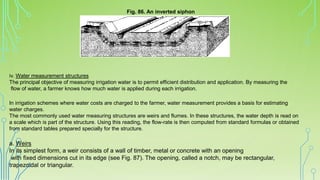
The irrigation system consists of several interconnected components that work together to transport water from its source to agricultural fields. The main intake structure or pumping station directs water into the irrigation system from sources like reservoirs or rivers. The conveyance system then transports water through canals to the distribution system of field ditches. These ditches carry water to individual fields for application using various field irrigation methods. The drainage system removes excess water from the fields. Canal structures like drops, turnouts, checks, and weirs are used to control water flow and distribution throughout the system.
CSR_Module5_Green Earth Initiative, Tree Planting Day
ย
MATERIAL #2 IRRIGATION PDF.pdf
1. IRRIGATION SYSTEM
The irrigation system consists of a (main) intake structure or (main) pumping station, a conveyance system,
a distribution system, a field application system, and a drainage system (see Fig. 69).
The (main) intake structure, or (main) pumping station, directs water from the source of supply, such as a
reservoir or a river, into the irrigation system.
The conveyance system assures the transport of water from the main intake structure or main pumping
station up to the field ditches.
The distribution system assures the transport of water through field ditches to the irrigated fields.
The field application system assures the transport of water within the fields.
The drainage system removes the excess water (caused by rainfall and/or irrigation) from the fields.
Fig. 69. An irrigation system
2. 5.1 Main intake structure and pumping station
5.1.1 Main intake structure
The intake structure is built at the entry to the irrigation system (see Fig. 70). Its purpose is to direct water
from the original source of supply (lake, river, reservoir etc.) into the irrigation system.
Fig. 70. An intake structure
3. 5.1.2 Pumping station
In some cases, the irrigation water source lies below the level of the irrigated fields. Then a pump must be
used to supply water to the irrigation system (see Fig. 71).
Fig. 71. A pumping station
4. There are several types of pumps, but the most commonly used in irrigation is the centrifugal pump.
The centrifugal pump (see Fig. 72a) consists of a case in which an element, called an impeller, rotates driven by
a motor (see Fig. 72b). Water enters the case at the center, through the suction pipe. The water is immediately
caught by the rapidly rotating impeller and expelled through the discharge pipe.
Fig. 72a. Diagram of a centrifugal pump
5. Fig. 72b. Centrifugal pump and motor
The centrifugal pump will only operate when the case is completely filled with water.
5.2 Conveyance and distribution system
The conveyance and distribution systems consist of canals transporting the water through the whole
irrigation system. Canal structures are required for the control and measurement of the water flow.
6. 5.2.1 Open canals
An open canal, channel, or ditch, is an open waterway whose purpose is to carry water from one place to
another.
Channels and canals refer to main waterways
supplying water to one or more farms. Field ditches have smaller dimensions and convey water from the farm
entrance to the irrigated fields.
i. Canal characteristics
According to the shape of their cross-section, canals are called rectangular
(a), triangular (b), trapezoidal (c), circular (d), parabolic (e), and irregular or natural (f) (see Fig. 73).
Some examples of canal cross-sections
The most commonly used canal cross-section in irrigation and drainage,
is the trapezoidal cross-section. For the purposes of this publication, only this type of canal will be considered.
The typical cross-section of a trapezoidal canal is shown in Figure 74.
7. Fig. 74. A trapezoidal canal cross-section
The freeboard of the canal is the height of the bank above the highest water level anticipated. It is required
to guard against overtopping by waves or unexpected rises in the water level.
8. The side slope of the canal is expressed as ratio, namely the vertical distance or height to the horizontal
distance or width. For example, if the side slope of the canal has a ratio of 1:2 (one to two), this means that
the horizontal distance (w) is two times the vertical distance (h) (see Fig. 75).
Fig. 75. A side slope of 1:2 (one to two)
The bottom slope of the canal does not appear on the drawing of the cross-section but on the longitudinal
section (see Fig. 76). It is commonly expressed in percent or per mil.
10. ii. Earthen Canals
Earthen canals are simply dug in the ground and the bank is made up from the removed
earth, as
illustrated in Figure 77a.
Figure 77a. Construction of an earthen canal
The disadvantages of earthen canals are the risk of
the side slopes collapsing and the water loss due to
seepage. They also require continuous maintenance
(Fig. 77b) in order to control weed growth and to
repair damage done by livestock and rodents.
Fig. 77b. Maintenance of an earthen canal
11. iii. Lined Canals
Earthen canals can be lined with impermeable materials to prevent excessive
seepage and growth of weeds (Fig. 78).
Fig. 78. Construction of a canal lined with bricks
Lining canals is also an effective way to control canal bottom and bank erosion. The materials mostly used for
canal lining are concrete (in precast slabs or cast in place), brick or rock masonry and asphaltic concrete (a
mixture of sand, gravel and asphalt).
The construction cost is much higher than for earthen canals. Maintenance is reduced for lined canals, but
skilled lab our is required.
12. 5.2.2 Canal structures
The flow of irrigation water in the canals must always be under control. For this purpose, canal structures are required.
They help regulate the flow and deliver the correct amount of water to the different branches of the system and onward to
the irrigated fields.
There are four main types of structures: erosion control structures, distribution control structures, crossing structures and water measurement
structures.
i. Erosion control structures
a. Canal erosion
Canal bottom slope and water velocity are closely related, as the following example will show.
A cardboard sheet is lifted on one side 2 cm from the ground (see Fig. 79a).
A small ball is placed at the edge of the lifted side of the sheet. It starts rolling downward, following the slope direction.
The sheet edge is now lifted 5 cm from the ground (see Fig. 79b), creating a steeper slope. The same ball placed on the
top edge of the sheet rolls downward, but this time much faster. The steeper the slope, the higher the velocity of the ball.
Fig. 79. The relationship between slope and velocity
13. Water poured on the top edge of the sheet reacts exactly the same as the ball. It flows downward and the
steeper the slope, the higher the velocity of the flow.
Water flowing in steep canals can reach very high velocities. Soil particles along the bottom and banks of an
earthen canal are then lifted, carried away by the water flow, and deposited downstream where they may block
the canal and silt up structures. The canal is said to be under erosion; the banks might eventually collapse.
b. Drop structures and chutes
Drop structures or chutes are required to reduce the bottom slope of canals lying on steeply sloping land in
order to avoid high velocity of the flow and risk of erosion. These structures permit the canal to be constructed
as a series of relatively flat sections, each at a different elevation (see Fig. 80).
Fig. 80. Longitudinal section of a series of drop structures
14. Drop structures take the water abruptly from a higher section of the canal to a lower one. In a chute, the water
does not drop freely but is carried through a steep, lined canal section. Chutes are used where there are big
differences in the elevation of the canal.
ii. Distribution control structures
Distribution control structures are required for easy and accurate water distribution within the irrigation system and on the farm.
a. Division boxes
Division boxes are used to divide or direct the flow of water between two or more canals or ditches. Water enters
the box through an opening on one side and flows out through openings on the other sides. These openings
are equipped with gates (see Fig. 81).
Fig. 81. A division box with three gates
15. b. Turnouts
Turnouts are constructed in the bank of a canal. They divert part of the water from the canal to a smaller one.
Turnouts can be concrete structures (Fig. 82a), or pipe structures (Fig. 82b).
Fig. 82a. A concrete turnout
Fig. 82b. A pipe turnout
c. Checks
To divert water from the field ditch to the field, it is often necessary to raise the water level in the ditch. Checks
are structures placed across the ditch to block it temporarily and to raise the upstream water level. Checks can
be permanent structures (Fig. 83a) or portable (Fig. 83b).
Fig. 83a. A permanent concrete check
16. Fig. 83b. A portable metal check
iii. Crossing structures
It is often necessary to carry irrigation water across roads, hillsides and natural depressions. Crossing structures, such as flumes,
culverts and inverted siphons, are then required.
a. Flumes
Flumes are used to carry irrigation water across gullies, ravines or other natural depressions.
They are open
canals made of wood (bamboo),
metal or concrete which often need to be supported by pillars (Fig. 84).
Fig. 84. A concrete flume
17. b. Culverts
Culverts are used to carry the water across roads. The structure consists of masonry or concrete headwalls at
the inlet and outlet connected by a buried pipeline (Fig. 85).
Fig. 85. A culvert
c. Inverted siphons
When water has to be carried across a road which is at the same level as or below the canal bottom, an
inverted siphon is used instead of a culvert. The structure consists of an inlet and outlet connected by a
pipeline (Fig. 86). Inverted siphons are also used to carry water across wide depressions.
18. Fig. 86. An inverted siphon
iv. Water measurement structures
The principal objective of measuring irrigation water is to permit efficient distribution and application. By measuring the
flow of water, a farmer knows how much water is applied during each irrigation.
In irrigation schemes where water costs are charged to the farmer, water measurement provides a basis for estimating
water charges.
The most commonly used water measuring structures are weirs and flumes. In these structures, the water depth is read on
a scale which is part of the structure. Using this reading, the flow-rate is then computed from standard formulas or obtained
from standard tables prepared specially for the structure.
a. Weirs
In its simplest form, a weir consists of a wall of timber, metal or concrete with an opening
with fixed dimensions cut in its edge (see Fig. 87). The opening, called a notch, may be rectangular,
trapezoidal or triangular.
19. Fig. 87. Some examples of weirs
A RECTANGULAR WEIR
A TRIANGULAR WEIR