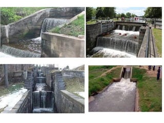
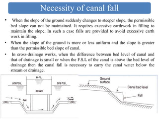
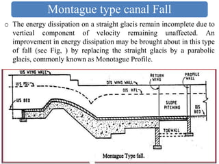
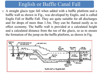
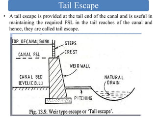
2. 1. Introduction
2. Methods of Irrigation
3. Water Requirement of Crops
4. Hydrological Cycle Catchment Area and Run-off
5. Canals
6. Canal Head Works
7. Regulatory and Cross Drainage works
8. Dams
9. Definitions of Hydraulic Structures with Sketches
10.Water logging and Drainage
11.Tube well Irrigation
12.River Training Works
Syllabus
5. Canal fall
• Whenever the available natural ground slope is steep than the
designed bed slope of the channel, the difference is adjusted by
constructing vertical ‘falls’ or ‘drops’ in the canal bed at suitable
intervals, as shown in figure below. Such a drop in a natural canal
bed will not be stable and, therefore, in order to retain this drop, a
masonry structure is constructed. Such a structure is called a Canal
Fall or a Canal drop.
6. • Irrigation canals are designed for a prescribed bed slope so that
velocity becomes non silting or non scouring. But if the ground
topography is such that in order to maintain the canal designed
slope, indefinite filling from falling ground level is to be made.
This indefinite filling is avoided by constructing a hydraulic
structure in the place of sudden bed level. This hydraulic structure
is called canal fall or drop. Beyond the canal fall, canal again
maintains its designed slope.
• Thus, a canal fall or drop is an irrigation structure constructed
across a canal to lower down its bed level to maintain the designed
slope when there is a change of ground level to maintain the
designed slope when there is change of ground level. This falling
water at the fall has some surplus energy. The fall is constructed in
such a way that it can destroy this surplus energy.
Canal fall
7. Necessity of canal fall
• When the slope of the ground suddenly changes to steeper slope, the permissible
bed slope can not be maintained. It requires excessive earthwork in filling to
maintain the slope. In such a case falls are provided to avoid excessive earth
work in filling.
• When the slope of the ground is more or less uniform and the slope is greater
than the permissible bed slope of canal.
• In cross-drainage works, when the difference between bed level of canal and
that of drainage is small or when the F.S.L of the canal is above the bed level of
drainage then the canal fall is necessary to carry the canal water below the
stream or drainage.
8. Location of canal fall
Location of canal fall depends upon the following factors:
1) Topography of canal
2) Economy of excavation or filling
• The above two will decide the location of canal fall across canal. By
understanding topographic condition we can provide the required
type of fall which will give good results. At the same time, the
provided falls is economical and more useful. So, economical
calculation is also important. Unbalanced earth work on upstream
and downstream result the project more uneconomical.
• The location of falls may also be influenced by the possibility of
combining it with a bridge., regulator or other works, since such
combinations often result in economy and better regulation. When a
fall is combined with a regulator and a bridge, it is called a fall
regulator with a road bridge.
9. Types of fall
• The important types of falls which were used in olden days and
those which are being used in modern days are described below:
1) Ogee falls
2) Rapids falls
3) Stepped falls
4) Trapezoidal notch falls
5) Well type falls
6) Simple vertical drop falls
7) Straight glacis falls
8) Montague type falls
9) English falls or baffle falls
10. Ogee Falls
• The ogee fall was constructed by Sir Proby Cautley on the Ganga
Canal. This type of fall has gradual convex and concave surfaces i.e.
in the ogee form. The gradual convex and concave surface is
provided with an aim to provide smooth transition and to reduce
disturbance and impact. A hydraulic jump is formed which dissipates
a part of kinetic energy. Upstream and downstream of the fall is
provided by Stone Pitching.
11. Rapid canal Fall
• The rapid fall is suitable when the slope of the natural ground
surface is even and long. It consists of a long sloping glacis with
longitudinal slope which varies from 1 in 10 to 1 in 20. For this, a
bed of rubble masonry is provided and it is finished with cement
mortar of 1:3 ratio. To maintain the slope of bed curtain walls are
provided at both upstream and downstream. Rapid falls are high
priced constructions.
12. Stepped Canal Fall
• It consists of a series of vertical drops in the form of steps. This steps
is suitable in places where sloping ground is very long and require a
long glacis to connect the higher bed level u/s with lower bed level
d/s. it is practically a modification of rapid fall. The sloping glacis is
divided into a number drops to bring down the canal bed step by step
to protect the canal bed and sides from damage by erosion. Brick
walls are provided at each drop. The bed of the canal within the fall
is protected by rubble masonry with surface finishing by rich cement
mortar.
13. Trapezoidal Notch Canal Fall
• It was designed by Reid in 1894. In this type a body or foundation
wall across the channel consisting of several trapezoidal notches
between side pier and intermediate pier is constructed. The sill of the
notches are kept at upstream bed level of the canal. The body wall is
made of concrete. An impervious floor is provided to resist the
scouring effect of falling water. Upstream and downstream side of
the fall is protected by stone pitching finished with cement grouting.
14. Well type Canal Fall
o In this type, water of canal from higher level is thrown in a well or a
cylinder from where it escapes from bottom. Energy is dissipated in
the well in turbulence. They are suitable for low discharges and are
economical also.
15. o Simple vertical drop fall or Sarda fall consists, single vertical drop which allows
the upstream water to fall with sudden impact on downstream. The downstream
acts like cushion for the upstream water and dissipate extra energy. canal u/s bed is
on the level of upstream curtain wall, canal u/s bed level is below the crest of
curtain wall. Floor is made of concrete u/s and d/s side stone pitching with cement
grouting is provided. This type of fall is used in Sarda Canal UP (India) and
therefore, it is also called Sarda Fall.
Simple vertical Drop Fall
16. o This is the modern type of construction, in which a raised crest is
constructed across the canal and a gentle straight inclined surface is
provided from raised crest to the downstream. The water coming
from upstream crosses the raised crest and falls on inclined surface
with sufficient energy dissipation.
Straight glacis Canal Falls
17. o The energy dissipation on a straight glacis remain incomplete due to
vertical component of velocity remaining unaffected. An
improvement in energy dissipation may be brought about in this type
of fall (see Fig, ) by replacing the straight glacis by a parabolic
glacis, commonly known as Monotague Profile.
Montague type canal Fall
18. o A straight glacis type fall when added with a baffle platform and a
baffle wall as shown in Fig., was developed by Englis, and is called
Englis Fall or Baffle Fall. They are quite suitable for all discharges
and for drops of more than 1.5m. They can be flumed easily as to
effect economy. The baffle wall is provided at a calculated height
and a calculated distance from the toe of the glacis, so as to ensure
the formation of the jump on the baffle platform, as shown in Fig.
English or Baffle Canal Fall
20. Canal Escapes
▪ Irrigation structures constructed to escape extra water from the canal
into some natural drain or nallah is called canal escape. They are
located at 5 to 10 km c/c along the length of major canal near the
natural drain.
▪ It is the structure required to dispose of surplus or excess water
from canal from time to time. Thus, a canal escape serves as safety
valve for canal system. It provides protection to the canal from
possible damage due to excess supply which may be due to mistake
in releasing water at head regulator or heavy rainfall that makes
sudden regular demand of water.
▪ The excess supply makes the canal banks vulnerable to failure due
to overtopping or dangerous leaks. Therefore, provision for
disposing this surplus water in form of canal escapes at suitable
intervals along the canal is essential.
▪ Moreover emptying canal for repair and maintenance and removal of
sediment deposited in the canal can also be achieved with the help of
canal escapes.
21. ▪ The importance of an escape is realized more, in case, a breach
occurs in a channel. If a breach occur, immediately the information
is sent to the head, so as to close down the channel supplies.
▪ But the water already contained in the channel from the head to the
breach site will cause wide spread damage if allowed to pass
through the breach.
▪ In such situation, the escape existing on upstream of the breach is
opened and most of water is allowed to escape and reduced the
damage. The minimum capacity of escape is generally kept as half
of the channel capacity at the point of escape.
Purpose or Objective of canal escapes :
1) To remove surplus water from an irrigation channel into a natural
drain.
2) To avoid damage to the channel by surplus water.
3) To provide the safety valve of canals.
4) It saves the d/s section of the canal from overflow of banks.
22. Types of Canal escapes
Depending upon the purpose, there can be three types of escapes:
1) Canal scouring escape
2) Surplus escape, and
3) Tail escape
23. Scouring Escape
• This escape is constructed for the purpose of scouring of excess silt
deposited in the head reaches from time to time. Hence, it is called
scouring escape. Here the sill of the regulator is kept at about 0.3 m
below the canal bed level at escape site. When deposited silt to be
scoured, a higher discharge than the FSL is allowed to enter the
canal from the head works. The gate of the escape is raised so as to
produce scouring velocity which remove the deposited silt. This
type of Escape has become obsolete as silt ejector provided in the
canal can produce better efficiency.
24. Surplus Escape
• It is also called regulator type. In this type sill of the escape is kept
at canal bed level and the flow is controlled by a gate. This type of
escapes are preferred now-a-days as they give better control and can
be used for employing the canal for maintenance.
25. Tail Escape
• A tail escape is provided at the tail end of the canal and is useful in
maintaining the required FSL in the tail reaches of the canal and
hence, they are called tail escape.
26. Head Regulator
▪ Regulators Constructed at the off taking point are called head
regulators. When it is constructed at the head of main canal it is
known as canal head regulator. And when it is constructed at the
head of distributary, it is called distributary head regulator.
Function:
1. To control the entry of water either from the reservoir or from
the main canal.
2. To control the entry of silt into off taking or main canal.
3. To serve as a meter for measuring discharge of water.
• The components of head regulator depends upon the size of canal
and location of head regulator. It consists of one or more gated
research openings with barrels running through the bank. For large
canals head regulators are flumed to facilitate the measurement of
discharge.
27.
28. • A Regulator Constructed in the main canal or parent canal
downstream of an off take canal is called cross- regulator. • It is
generally constructed at a distance of 9 to 12 km along the main
canal and 6 to 10 km along branch canal.
Function:
1) To Control the flow of water in canal system
2) To feed the off taking Canals
3) To enable closing of the canal breaches on the d/s
4) To provide roadway for vehicular traffic
• For Cross Regulators abutments with grooves and piers are
constructed parallel to the parent canal. The sill of regulation is kept
little higher than the u/s bed level of canal across which it is
constructed. Vertical lift gates are fitted in the grooves. The gates can
be operate from the road.
Cross Regulator
33. Canal Outlets
• A canal outlet or a module is a small structure built at the head of the
water course so as to connect it with a minor or a distributary
channel. It acts as a connecting link between the system manager
and the farmers.
• Since the outlets release water to each and every farm watercourse,
such structures are more numerous than any other irrigation
structure. Hence it is essential to design an outlet in such a way that
it is reliable and be also robust enough such that it is not easily
tampered with.
• Further the cost of an outlet structure should be low and should
work efficiently with a small working head, since a larger working
head would require higher water level in the parent channel resulting
in high cost of the distribution system. Discharge through an outlet
is usually less than 0.085 cumecs.
34.
35. Canal outlet
An outlet must fulfill the following conditions:
1) It should pass a constant discharge under all conditions of flow.
2) It should provide sufficient quantity of water to the fields for
irrigation purposes.
3) It should draw its fare share of silt in proportion to the
discharge in the distributary.
4) It should be simple and strong.
5) It should be cheap and durable.
6) It should work efficiently with a small working head.
36. Types of Canal outlet
• Outlets are classified as :
1. Non modular outlet
2. Semi modular outlets
3. Modular outlets
1) Non modular outlets: When the discharge of the outlets fluctuate
according to the working head i.e, the difference in levels between
the water level of the distributary and that of the water course, the
outlets are termed as Non modular outlets. The discharge through
such a module, therefore varies widely with either a change in the
water level of the distributary or that of the water course. The
common example of these types outlets are:
I. Open sluice
II. Drowned pipe outlet
37.
38. 2) Semi modular outlets: When the discharge of the outlets depends
only on the water level in the distributary and not on that of the
water course provided a required working head is available, the
outlet is termed as semi modular outlet. The discharge through such
an outlet will therefore increase with a rise in the distributary water
surface level and vice versa. Due to construction, a super-critical
velocity is ensured in the throat and thereby allowing the formation
of a jump in the expanding flume. The formation of hydraulic jump
makes the outlet discharge independent of the water level in water
course, thus making it a semi module.
The common example of these types outlets are:
I. Open flume
II. pipe outlet
III. Venturi flume
Types of Canal outlet
40. Types of Canal outlet
3) Modular outlets: When the discharge of the outlets is independent
of the water level in the water course and the distributary, the outlet
is termed as a modular outlet.
4) The common example of this type outlets is:
I. Gibb’s Module