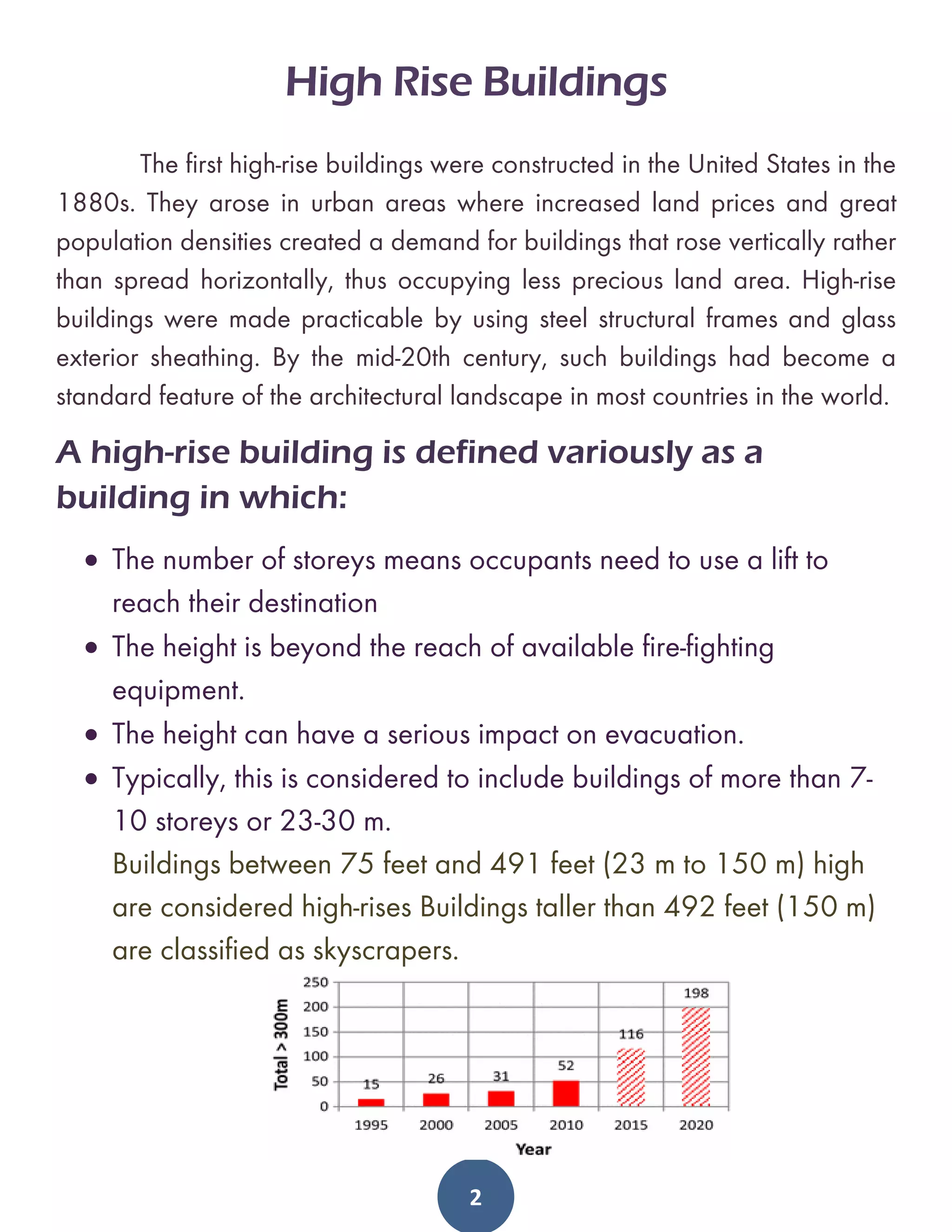
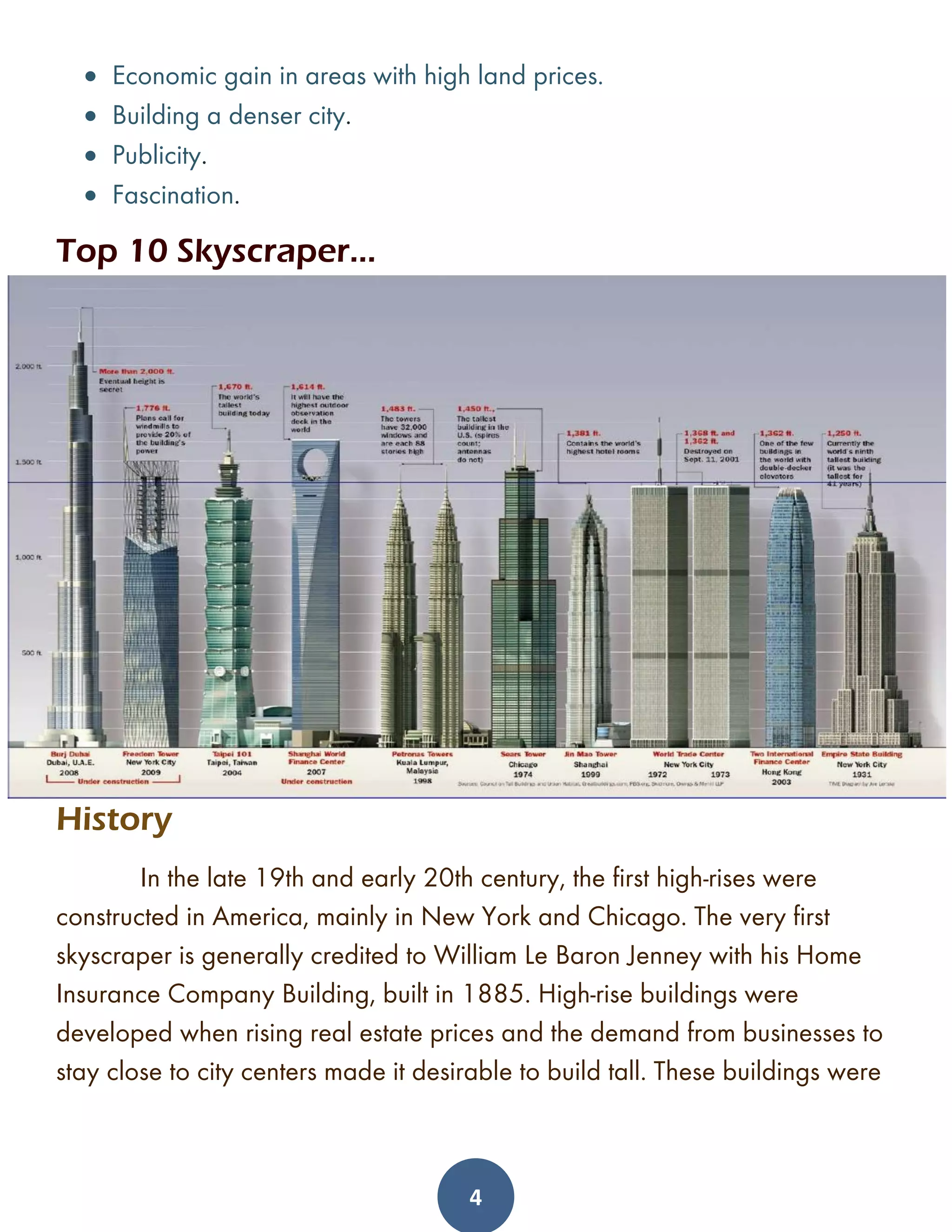
SlideShare a Scribd company logo
1 of 56
Download to read offline
1
High Rise Buildings
2
High Rise Buildings
The first high-rise buildings were constructed in the United States in the
1880s. They arose in urban areas where increased land prices and great
population densities created a demand for buildings that rose vertically rather
than spread horizontally, thus occupying less precious land area. High-rise
buildings were made practicable by using steel structural frames and glass
exterior sheathing. By the mid-20th century, such buildings had become a
standard feature of the architectural landscape in most countries in the world.
A high-rise building is defined variously as a
building in which:
• The number of storeys means occupants need to use a lift to
reach their destination
• The height is beyond the reach of available fire-fighting
equipment.
• The height can have a serious impact on evacuation.
• Typically, this is considered to include buildings of more than 7-
10 storeys or 23-30 m.
Buildings between 75 feet and 491 feet (23 m to 150 m) high
are considered high-rises Buildings taller than 492 feet (150 m)
are classified as skyscrapers.
3
Why Tall Buildings?
There are several possible reasons why a high-rise is built. It is
important to understand what the driving force behind the building is, as it
decides what is central in the design. Building as economically as possible is
a quite different starting point from wishing to create a new icon in the city.
Historically, high-rise buildings were developed in response to increasing
land prices and the wish to reside close to the city centers. In large cities
where land prices are very high, such as New York and London, this is a
viable reason today. Flatiron building, New York is an example of where the
high prices in the city made a difficult plot economic to use for a tall building.
Another reason to build tall is the wish to create a denser city. This enables
more people to live closer to their work places and amenities, which
decreases the need for transport. It gives people the ability to have more
sustainable lifestyles. High-density areas also have the amount of people
needed for an efficient public transport system. A high-rise building is planned
for the Chalmers campus.
A common aim is also to create a new iconic building. It may be an icon of a
country, a city, an organization or an individual. There are many examples of
this and in many regions, cities compete to build even taller than their rivals
do. An iconic building gets publicity and can serve marketing purposes and
symbolize power.
A related reason that is not to be neglected is that many are fascinated by
high-rises. They are prepared to pay a premium to live in or have their office
in a high-rise. This fascination can be seen from the comments in the case
study.
The main reasons to build tall can be summarized as:
4
• Economic gain in areas with high land prices.
• Building a denser city.
• Publicity.
• Fascination.
Top 10 Skyscraper…
History
In the late 19th and early 20th century, the first high-rises were
constructed in America, mainly in New York and Chicago. The very first
skyscraper is generally credited to William Le Baron Jenney with his Home
Insurance Company Building, built in 1885. High-rise buildings were
developed when rising real estate prices and the demand from businesses to
stay close to city centers made it desirable to build tall. These buildings were
5
enabled by the development of cast iron and steel, and made feasible by
inventions such as the security elevator and mass-produced building elements.
The first skyscraper boom culminated in the 443-meter high Empire State
Building, which was completed in 1931. It would take until the 1960’s
before high-rises again became popular. Engineers had then developed the
tube structure, where load-bearing outer walls carry vertical and horizontal
loads. This enabled a very material efficient structure where the amount of
steel used could almost be halved compared to earlier structures. Examples
of buildings in this style are John Hancock Center and Sears Tower in
Chicago, designed by engineer Fazlur Kahn and architect John Graham.
John Hancock Center is constructed as a huge truss,, and Sears Tower has
nine tubes consisting of stiff frames bundled together to form the tower.
6
Other structural options have also been explored in the last few decades. The
world’s tallest building as of now, Burj Khalifa, is constructed using a
symmetrical Y-shaped plan with stabilizing struts in three directions. It was
built partly in concrete, which is a very common construction material in high-
rises.
In Sweden, with its old city centers and history of lower buildings, high-rise
buildings have not started to appear until the last few decades. The tallest
building in Sweden as of today is the Turning Torso in Malmö, reaching 190
meters above the ground. It is designed by Santiago Calatrava and
completed in 2005. Outside Stockholm the Kista Science Tower (124 m) by
7
White Arkitektkontor AB, and Scandic Viktoria Tower (117 m) by Wingårdhs
Arkitektkontor AB are two other high-rises from the early 21st century
Living in a High-Rise Building
Advantages Disadvantages
+ Views
+ Daylight
+ Facilities
+ Privacy
+ Trendiness
- Anonymity
- Vibrations
- Waiting for elevators
- Safety concerns
- Unsuitable for pets
Loads on high rise buildings
• Gravitational Load Capacity
Disregarding everything else except material efficiency, it is always
more efficient to build a single-story building, rather than several stories.
Stacking floors on top of each other means an increase of loads on the lower
stories and therefore an increased amount of material needed in vertical
load-bearing elements. The area covered by columns and walls on each floor
is costly, regarding both structural material and lost floor space. The taller the
building is, the larger this problem becomes.
The effect is illustrated, where the same loads are applied to a conceptual
single-story building and a four-story tower, with the same total floor area. As
can be seen, the total loads on the lower stories in the tower become
increased, since the loads from above are added. The vertical load-bearing
elements will therefore need to be bigger in the tower than in the single-story
8
building. The columns on a given story in a high-rise need to carry the weight
of all the stories above.
This includes the loads from floor slabs, installations and other materials as
well as people, furniture and movable elements. They also need to carry the
weight of all columns on floors above.
To design vertical elements in a simplified manner, the self-weight and
imposed load on each story can be calculated. Then the loads from stories
above can be added to those of the story in question to get the total load to
design the columns for.
However, the weight of the columns above can be very large at the lower
stories of a tall building. This is because the columns need to increase in size
the further down the tower they are placed, in response to the increasing
loads from above. To accommodate this effect in the design, an iterative
calculation is needed, described below.
The first step is to size columns according to simplified loads, then the weight
of these columns can be calculated and added to the loads on each floor.
Then the column size can be re-calculated with better precision. More
iterations can be made to get even more accurate results, but one iteration is
probably enough, even for more detailed design. This is because a very
9
precise solution is unnecessary, since it is unlikely that columns will be sized
individually for each floor. Optimizing the column sizes with regards to
material only is not the most economical solution, since there are other
factors, such as formwork and connections, to consider. In the Karlatornet
Gothenburg tower, the columns change cross section every 10 to 15 floors.
The accumulated loads on each floor are used to calculate needed column sizes. Then the weight of the columns is
added to the other loads to get the total loads on each floor
As explained, much of the loads and mass are concentrated to the lower part
of a high-rise building. If the building is reduced in height it structurally means
10
that the bottommost part is removed, which means losing much of the loads.
A relatively small reduction in height can therefore save a lot of material.
Figure 14 below shows a diagram of vertical loads, which can be
approximated as linearly distributed over the height of the building. The
figure shows that reducing the building to 7/10 of its height means reducing
the vertical loads to half.
➢Wind loads
The structural systems of tall buildings must carry vertical gravity loads,
but lateral loads, such as those due to wind and earthquakes, are also a major
consideration. Maximum 100-year-interval wind forces differ considerably
with location; in the interiors of continents they are typically about 100
kilograms per square meter (20 pounds per square foot) at ground level. In
coastal areas, where cyclonic storms such as hurricanes and typhoons occur,
maximum forces are higher, ranging upward from about 250 kilograms per
square meter (50 pounds per square foot). Wind forces also increase with
building height to a constant or gradient value as the effect of ground friction
diminishes. The maximum design wind forces in tall buildings are about 840
kilograms per square meter (170 pounds per square foot) in typhoon areas.
The effect of wind forces on tall buildings is twofold. A tall building may be
thought of as a cantilever beam with its fixed end at the ground; the pressure
of the wind on the building causes it to bend with the maximum deflection at
the top. In addition, the flow of wind past the building produces vortices near
the corners on the leeward side; these vortices are unstable and every minute
or so they break away downwind, alternating from one side to another. The
change of pressure as a vortex breaks away imparts a sway, or periodic
motion, to the building perpendicular to the direction of the wind. Thus, under
wind forces there are several performance criteria that a high-rise structure must
11
meet. The first is stability—the building must not topple over; second, the
deflection, or sides way at the top, must not exceed a maximum value (usually
taken as 1/500 of the height) to avoid damage to brittle building elements
such as partitions; and, third, the swaying motion due to vortex shedding must
not be readily perceptible to the building occupants in the form of acceleration,
usually stated as a fraction of gravity, or g. The threshold of perception of
lateral motion varies considerably with individuals; a small proportion of the
population can sense 0.003 g or 0.004 g. The recommendation for motion
perception is to limit acceleration to 0.010 g for wind forces that would recur
in 10-year intervals. The fourth criterion involves the natural period of the
building structure. This is the vibration period at which the swaying cantilever
motions of the building naturally reinforce and enhance each other and could
become large enough to damage the building or even cause it to collapse. The
natural period of the building should be less than one minute, which is the
period of vibration due to the shedding of wind vortexes.
WIND TURBULENCE:
When any moving air mass meets an obstruction, such as building, it
responds like any fluids by moving to each side, then rejoining the major
airflow. The Venturi effect is one type of turbulent wind action. Turbulence
develops as the moving air mass is funneled through the narrow space
between two tall buildings. The corresponding wind velocity in this space
exceeds the wind velocity of the major airflow
Earthquake loads
Earthquake or seismic forces, unlike wind forces, are generally
confined to relatively small areas, primarily along the edges of the slowly
12
moving continental plates that form the Earth’s crust. When abrupt movements
of the edges of these plates occur, the energy released propagates waves
through the crust; this wave motion of the Earth is imparted to buildings resting
on it. Timber frame buildings are light and flexible and are usually little
damaged by earthquakes; masonry buildings are heavy and brittle and are
susceptible to severe damage. Continuous frames of steel or reinforced
concrete fall between these extremes in their seismic response, and they can
be designed to survive with relatively little damage.
In two major earthquakes involving large numbers of high-rise buildings, in
Los Angeles in 1971 and Mexico City in 1985, lateral accelerations due to
ground motions in several tall buildings were measured with accelerometers
and were found to be of the order of 0.100 to 0.200 g. In Los Angeles,
where the period of the seismic waves was less than one second, most steel-
frame high rises performed well with relatively little damage; continuous
concrete frames also generally performed well, but there was considerable
cracking of concrete, which was later repaired by the injection of epoxy
adhesive. In Mexico City, however, the period of the seismic waves was quite
long, on the order of a few seconds. This approached the natural frequency
of many tall structures, inducing large sides way motions that led to their
collapse. Based on this experience, determination of the seismic performance
criteria of buildings involves the lateral resistance of forces of 0.100 to 0.200
g and consideration of the natural period of the building in relation to the
period of seismic waves that can be expected in the locality. Another
important factor is the ductility of the structure, the flexibility that allows it to
move and absorb the energy of the seismic forces without serious damage.
The design of buildings for seismic forces remains a complex subject,
however, and there are many other important criteria involved
13
Tuned Mass Damper
Tuned mass absorbers constitute an efficient means of introducing damping into
structures prone to vibrations, e.g. bridges and high-rise buildings. The original idea is
due to Frahm in 1909, who introduced a spring supported mass, tuned to the natural
frequency of the oscillation to be reduced. that the introduction of a damper in parallel
with the spring support of the tuned mass leads to improved behavior, e.g. in the form of
amplitude reduction over a wider range of frequencies. A detailed analysis of the
frequency response properties of the tuned mass absorber has recently been presented
by Krenk who demonstrated that the classic frequency tuning leads to equal damping
ratio of the two complex modes resulting from the coupled motion of the structural mass
and the damper mass. An optimal damping ratio of the absorber was determined that
improves on the classic result of Brock. These results are all based on a frequency
response analysis, where a root locus analysis can be used to determine the complex
natural frequencies of the modes and thereby the damping ratio, while optimal response
characteristics are obtained by consideration of the frequency response diagrams for
the response amplitude. The results can be obtained in explicit form only when the
original structure is undamped. Many of the vibration problems involving tuned mass
dampers involve random loads, e.g. due to wind or earthquakes. In the random load
14
scenario, the response is characterized by its variance, determined as a moment of the
spectral density. This leads to a different approach to the determination of optimal
parameters and to somewhat different optimal parameter values.
Foundations
The foundations of high-rise buildings must sometimes support very heavy gravity
loads, and they usually consist of concrete piers, piles, or caissons that are sunk into the
ground. Beds of solid rock are the most desirable base, but ways have been found to
distribute loads evenly even on relatively soft ground. The most important factor in the
design of high-rise buildings, however, is the building’s need to withstand the lateral
forces imposed by winds and potential earthquakes. Most high-rises have frames made
of steel or steel and concrete. Their frames are constructed of columns (vertical-support
members) and beams (horizontal-support members). Cross-bracing or shear walls may
be used to provide a structural frame with greater lateral rigidity in order to withstand
wind stresses. Even more stable frames use closely spaced columns at the building’s
perimeter, or they use the bundled-tube system, in which a number of framing tubes are
bundled together to form exceptionally rigid columns.
15
There are a number of characteristics of tall buildings that can
have a significant influence on foundation design, including
the following:
• The building weight, and thus the vertical load to be supported by the
foundation, can be substantial. Moreover, the building weight increases non-linearly
with height, and so both ultimate bearing capacity and settlement need to be
considered carefully.
• High-rise buildings are often surrounded by low-rise podium structures which are
subjected to much smaller loadings. Thus, differential settlements between the
high- and low-rise portions need to be controlled.
• The lateral forces imposed by wind loading, and the consequent moments
on the foundation system, can be very high. These moments can impose increased
vertical loads on the foundation, especially on the outer piles within the foundation
system. The structural design of the piles needs to take account of these increased
loads that act in conjunction with the lateral forces and moments.
• The wind-induced lateral loads and moments are cyclic in nature. Thus,
consideration needs to be given to the influence of cyclic vertical and lateral
loading on the foundation system, as cyclic loading has the potential to degrade
foundation capacity and cause increased settlements.
• Seismic action will induce additional lateral forces in the structure and also
induce lateral motions in the ground supporting the structure. Thus, additional lateral
forces and moments can be induced in the foundation system via two mechanisms:
1. Inertial forces and moments developed by the lateral excitation of the
structure;
2. Kinematic forces and moments induced in the foundation piles by the action of
ground movements acting against the piles.
• The wind-induced and seismically induced loads are dynamic in nature, and as
such, their potential to give rise to resonance within the structure needs to be
assessed. The risk of dynamic resonance depends on a number of factors, including
the predominant period of the dynamic loading, the natural period of the structure
and the stiffness and damping of the foundation system.
16
• The dynamic response of tall buildings poses some interesting structural and
foundation design challenges. In particular, the fundamental period of
vibration of a very tall structure can be very high (10 s or more), and
conventional dynamic loading sources such as wind and earthquakes have a much
lower predominant period and will generally not excite the structure via the
fundamental mode of vibration. However, some of the higher modes of vibration will
have significantly lower natural periods and may well be excited by wind or seismic
action. These higher periods will depend primarily on the structural characteristics but
may also be influenced by the foundation response characteristics.
Factors affecting foundation selection
The factors that may influence the type of foundation selected to support a tall
building include the following:
• Location and type of structure.
• Magnitude and distribution of loadings.
• Ground conditions.
• Access for construction equipment.
• Durability requirements.
• Effects of installation on adjacent foundations, structures, people.
• Relative costs.
• Local construction practices.
Structural member:
Beam:
Beam is a rigid structural member designed
to carry and transfer loads across spaces to
supporting elements.
Column:
A rigid relativity slender structural member designed
primarily to support axial compressive loads
applied at the member ends. In high rise buildings it
can be use as mega column,
concrete filled tubular (CFT) etc.
17
Shear wall:
A vertical diaphragm or wall acting as a thin,
deep cantilever beam in loads to the ground
foundation.
Bracing:
It is a structural element for positioning,
supporting, strengthening or restraining the
member of a structural frame.
Core:
Core is one of the most important structural and functional
elements of the high-rise building.
The core of a building is the area reserved for elevators’
stairs,
mechanical equipments and the vertical shafts that are
necessary
for ducts, pipes and wires.
Its wall is also the most common location for the vertical wind
bracing.
The placement of the service core stems from four
generic types which are:
• Central core
• Split core
• End core
• Atrium core
18
Types of High-Rise Buildings Structural Systems ...
1. Braced frame structural system
• Braced frames are cantilevered vertical
trusses resisting laterals loads primarily
diagonal members that together with the
girders, form the “web” of the vertical
truss, with the columns acting as the
“chords’’.
• Bracing members eliminate bending in
beams and columns.
• It is used in steel construction
• This system is suitable for multistory
building in the low to mid height range.
• efficient and economical for enhancing
the lateral stiffness and resistance of
rigid frame system.
• This system permits the use of slender
members in a building.
• An outstanding advantage of braced
frame is that, it can be repetitive up the
height of the building with obvious
economy in design and fabrication.
• However, it might obstruct internal planning and the location of doors and
windows. That is why it shall be incorporated internally along with lines of
walls and partitions.
19
Most braced frames are concentric. This means that, where members intersect
at a node, the centroid of each member passes through the same point.
Concentrically braced frames can further be classified as either ordinary or
special. Ordinary concentric braced frames (OCBFs) do not have extensive
requirements regarding members or connections, and are frequently used in
areas of low seismic risk. OCBF steel frame buildings originated in Chicago
and reinforced concrete frames originated in Germany and France – areas
where earthquakes were not an engineering consideration. Accordingly,
special concentrically or eccentrically braced frames were later developed
with extensive design requirements, and are frequently used in areas of high
seismic risk. The purpose of the concentrically- or eccentrically-braced design
is to ensure adequate ductility (i.e., to stretch without breaking suddenly).
Types of Bracing Systems Used in Multi-Storey Steel
Structures
There are two major bracing systems:
20
• Vertical bracing system
• Horizontal bracing system
Vertical Bracing System for Multi-Storey Steel Structures
Vertical bracing as shown in Figure-2 are diagonal bracings installed
between two lines of columns. Not only does it transfer horizontal loads to
the foundations (create load path for horizontal forces) but also it withstands
overall sway of the structure.
Configurations of vertical bracings include cross diagonals (cross bracing)
and single diagonal. In the former case, bracings are slender and withstand
tension forces only, so they will not resist compression forces.
Therefore, tensile diagonals provide necessary lateral stability in addition to
the floor beams that act as a part of bracing system. Figure-2 shows the
placement of cross bracings between two lines of columns.
Fig.2: Vertical Diagonal Bracing Provided Between Two Lines of Columns
21
As far as the single diagonal bracing is concerned, it is designed to
resist both tension forces and compression forces. The arrangement of
diagonal bracing is illustrated in Figure-3.
Bracing elements are commonly placed at nearly 45° because it not only
offers an efficient system compare with other systems but also strong and
compact connections between bracing member and beam-column juncture
will be achieved.
It is worth mentioning that, if the bracing member inclination is smaller than
45° (angle from vertical), then the sway sensitivity of the structure would be
increased whereas wider bracing member arrangement provide greater
structural stability.
Fig.3: Single Bracing Provides Resistance Against Compression and Tension
What Are the Forces that Vertical Bracing Should Be Designed to
Resist?
Vertical bracing systems are required to be designed to resist wind forces,
equivalent horizontal forces that represent the influence of initial imperfections
and second order effects caused by frame sway in the case of the flexible
frame.
22
How Many Vertical Bracing Planes Should be Installed?
It is recommended to provide at least three vertical bracing planes to provide
adequate resistance in both directions in plan and against torsion forces
around vertical axis of the structure.
If higher number of vertical planes of bracing is provided, it would enhance
structure stability. Practically, the number of vertical plans of bracing is installed
for multistory steel structures.
It is recommended to employ minimum two vertical planes of bracing in each
orthogonal direction to avoid disproportionate collapse. Important part of the
structure should be braced using more than one plane of vertical planes to
prevent progressive collapse.
Locations of Vertical Bracing System in Multi-Story Structure
The location of vertical planes of bracing should be determined carefully. It is
advised to place the vertical bracing planes at furthest point of the structure to
withstand torsion forces that may occur due to horizontal forces.
Horizontal Bracing System for Multi-Storey Steel Structures
Horizontal bracing systems purpose is the transfer of horizontal loads from
columns at the perimeter of the structure to the planes of vertical bracing.
The horizontal forces on perimeter columns are generated because of wind
force pressure on the cladding of the structure.
There are two major types of horizontal bracing systems which are used in the
multistory braced steel structure namely: diaphragms and discrete triangulated
bracing.
23
Regarding diaphragms, there are various types of floor systems that some
of them provide perfect horizontal diaphragm such as composite floors
whereas others such as precast concrete slabs need specific measures to
satisfactory serve their purpose.
For example, steel work and precast concrete slab should be joint together
properly to avoid relative movements.
As far as discrete triangulated bracing is concerned, this type of bracing
is considered when floor system cannot be used as a horizontal bracing
system.
It is a horizontal system of triangulated steel bracing placed in each orthogonal
direction. The horizontal bracing is placed between supports which commonly
are locations of vertical bracings
Regarding bracing at roof level, wind girder is used to resist horizontal forces
at the top of the columns.
24
2. Rigid frame structural system
DEFINING RIGID FRAME CONSTRUCTION
In this type of frame, the beam to column connections are classified as
rigid, hence the name. The frame is designed to transmit beam end moments
and shear forces into the columns without bracing systems to resist lateral loads.
The members can be straight or tapered.
The frame stability if only provided by the rigid connections and member
stiffness. It looks like post and beam but is significantly stronger and able to
hold vertical loads.
Local beam-column connection rotations are not considered in global frame
analysis; the connections are designed to transmit the resulting beam end
movements and shear forces into the columns.
The joints are not always fully fixed to either horizontal or vertical members;
when the beam rotates from a vertical load, the columns rotate with it. This
allows the joint to rotate as a unit and members maintain the same angular
relationships during the rotation.
Rigid frame buildings are highly adaptable and flexible in design. Doors and
windows can be placed anywhere, and HVAC units can be placed on the roof
or the side. The exterior can easily be dressed to look like any envelope type
including stone, brick, or wood.
Rigid frame, sometimes called continuous frame, offers a rotational stability that
enhances how it carries vertical loads, increasing the longevity of the entire
structure. Besides rigid frame, the same framing principles are used in the
simple frame and partially restrained frame buildings.
25
The joint connections can be fully fixed-end with fully restrained connections
that cannot rotate, or they can be "pin connections," in which the members can
freely rotate.
DIFFERENCES BETWEEN POST AND BEAM AND RIGID FRAME
Post and Beam: When a vertical load weighs on a common post and beam
structure, it is carried by a horizontal member and then shifted by bending to
columns or vertical members. The beam is simply supported by its columns,
sitting on top of them so that the ends of the beams can rotate on top of the
columns with no restraint. The result is that the horizontal members of the
structure then only carries axial forces.
Rigid Frame: When a rigid frame structure is subjected to a vertical load, it
is also picked up by the beams and eventually transferred through the
columns to the ground. However, the joints are strongly connected,
preventing any free rotation from occurring at the beams ends. This slight
difference changes everything about the behavior of the beams, which is now
the same as a fix-ended beam.
Rigid frame construction provides many benefits, such as decreased
deflections, decreased internal bending moments, and increased rigidity.
However, the columns are experiencing some degree of internal bending
themselves as the beams stay rigid.
HOW IS IT DESIGNED?
The connections of the joints in rigid frame construction vary between being
fully fixed-end, in which the connection offers full restraint and no ability to
rotate and pin connection, where the members are completely free to rotate.
This relationship is referred to the relative stiffness of the horizontal and
vertical members.
26
From a designer’s perspective, a rigid frame structure can be designed smaller
than other post and beam systems. This is because internal bending moments
are reduced by the rigidity. On the other hand, the columns or vertical members
should be designed to be a bit larger, since they are carrying both axial loads
and internal bending moments.
MOMENT RESISTING CONNECTIONS
The so-called rigid connections are typically full depth end-plate connections
and extended end-plate connections. The most common of these is the bolted
end-plate beam-to-column connection. The selection depends on the budget.
Welded connections can be used in place of the bolted end-plate, especially
in seismically active regions. Welded connections can provide full moment
continuity but tend to be on the expensive side. If used, the welded
connections should be prefabricated rather than welded on-site.
Site-bolting takes less time and minimizes labor costs.
BUILDING APPLICATIONS
Rigid frame is found in a wide variety of building styles and uses:
• Warehouses
• Retail stores
• Churches
• Plants
• Agricultural buildings
• Equipment shelters
• Multi-story buildings of any height
27
Rigid frame buildings are typically used when there are special requirements
such as medical centers, research facilities, white rooms, and structures
housing equipment sensitive to vibrations and deflection.
BENEFITS OF RIGID FRAME CONSTRUCTION
Beyond the clear span capabilities, which provide open spaces with no
center columns or bracing systems, rigid span steel building retains all the
benefits of any metal building.
• Cost-effective
• Energy-efficient
• Floors are not sensitive to vibration
• Connections perform better in load reversal situations and earthquakes
There are a few disadvantages is that the connections are more
complex and can complicate the erection process. The initial cost of the
structure is greater as well, but the investment is easily returned by the long
life of the building.
Rigid frame construction provides all the benefits of metal buildings and
introduces very few drawbacks. Rigid frame allows designers to create large,
clear-span spaces that can be used for almost anything. Both the interior and
exterior are flexible in appearance while giving you the strength of steel.
Rigid frame has been a hit for over a century. You can still see the evidence in
cities today.
Summary…
• In rigid frame structure, beams and columns are constructed monolithically
to withstand moments imposed due to loads.
28
• The lateral stiffness of a rigid frame depends on the bending stiffness of the
columns, girders and connections in-plane
• It is suitable for reinforced concrete buildings.
• It may be used in steel construction as well, but the connections will be costly.
• One of the advantages of rigid frames is the likelihood of planning and fitting
of windows due to open rectangular arrangement.
• Members of rigid frame system withstand bending moment, shear force, and
axial loads.
• 20 to 25 storey buildings can be constructed using rigid frame system.
• Advantages of rigid frame include ease of construction, labors can learn
construction skills easily, construct rapidly, and can be designed
economically.
• Maximum beam span is 12.2m and larger span beams would suffer lateral
deflection.
• A disadvantage is that the self-weight is resisted by the action from rigid
frames.
• Finally, Burj Al Khalifa which is the tallest structure in the world is constructed
using rigid frame system.
3. Shear wall system
What is a Shear Wall?
Shear wall is a structural member in a reinforced concrete framed structure to
resist lateral forces such as wind forces. Shear walls are generally used in
high-rise buildings subject to lateral wind and seismic forces.
In reinforced concrete framed structures, the effects of wind forces increase in
significance as the structure increases in height. Codes of practice impose
limits on horizontal movement or sway.
29
Limits must be imposed on lateral deflection to prevent:
• Limitations on the use of building,
• Adverse effects on the behavior of non-load bearing elements,
• Degradation in the appearance of the building,
• Discomfort for the occupants.
Generally, the relative lateral deflection in any one storey should not exceed
the storey height divided by 500.
The figure below shows the deflected profiles for a shear wall and a rigid
frame.
Difference between Column & Shear Wall
CONCRETE COLUMN SHEAR WALL
Ratio of breadth/width < 0.4 Ratio of breadth/width > 0.4
Concrete columns minimum width should be
200 mm as per Indian Standard. However,
many codes prefer it be of 300 mm for seismic
resistant.
Shear wall minimum width should be 150
mm as per Indian Standard.
Concrete columns are less resistant to
Earthquake as compared to shear wall.
Shear wall is hugely resistant to Earthquake
as compared to Column.
Normally concrete columns are provided at
ends of the room as per structural plan.
Shear walls run along the full length of
walls.
Concrete columns cross-section can be square,
rectangle, circular, I shape, L shape.
Shear wall cross section is like a vertically
oriented wide beam.
30
Lateral load is resisted by flexural deformation. Lateral load is resisted by shear
deformation.
Minimum steel in RCC Column as per different
codes:
(a) Indian Standard – 0.80%.
(b) American Standard – 1.0 %
(c) British Standard – 0.4 %
Minimum steel in RCC Shear as per
different codes:
(a) Indian Standard – 0.25%.
(b) American Standard – 0.25%
(c) British Standard – 0.4 %
Clear surface is not possible as column
offset are seen at corners.
• Clear surface without any offset is possible.
Normally consumption of concrete is less when
compared to shear wall system.
• Normally consumption of concrete is more
when compared to beam column system.
• Normally more consumption of bricks/blocks. Normally less consumption of
bricks/blocks.
• From an aesthetic point of view column is not
as good as shear wall.
• From an aesthetic point of view shear wall
is better than column.
Beam-Column System is more efficient and
preferred for low rise structure.
• Shear wall system is more efficient for high
rise structure.
Finished corners are not possible. Finished corners are possible.
Provision of openings for door/window in
column system is easy.
• Provision of openings in shear wall system is
tedious and needs special design skills.
• Less carpet area is available as compared to
shear wall.
• More carpet area is available as compared
to column beam system.
Needs skills for the placement of concrete
column.
Needs advanced skills for its placement
because if not kept at proper location it
may lead to adverse effect.
31
The most convenient place to locate shear wall is an external blank wall on
edges or on two parallel edges so that stiffness of structure is maintained in
best possible way. It should be spaced symmetrically so that center of gravity
(c.g.) of structure remains at center and there is not much eccentricity on
application of lateral loads like Seismic, wind etc. So, its placement needs
special skills and experience because if not placed at proper location it
would lead to adverse behavior.
Wind and Seismic loads are most common loads that shear walls are
designed to carry. It is competitive with steel if economically designed and
executed.
32
Summary…
• It is a continuous vertical wall constructed from reinforced concrete or
masonry wall.
• Shear walls withstand both gravity and lateral loads, and it acts as narrow
deep cantilever beam.
• Commonly, constructed as a core of buildings
33
• It is highly suitable for bracing tall buildings either reinforced concrete or
steel structure. This because shear walls have substantial in plane stiffness
and strength.
• Shear wall system is appropriate for hotel and residential buildings where
the floor-by floor repetitive planning allows the walls to be vertically
continuous.
• It may serve as excellent acoustic and fire insulators between rooms and
apartments.
• Shear wall structural system can be economical up to 35 stories building
structure.
• Shear walls need not to be symmetrical in plan, but symmetry is preferred
in order to avoid torsional effects.
4. Wall-frame system (dual system)
The lateral load-resisting structure
comprises of moment frames and
shear walls acting together in the
same direction, and it is mostly
applicable to reinforced concrete
structures. Due to wall slenderness, the
structural system cannot be classified
as a Wall system; however shear
walls interact with the moment frames
and resist seismic effects. The walls are usually solid (not perforated by
openings) and they can be found around the stairwells, elevator shafts,
and/or at the perimeter of the building. The walls may have a positive effect
34
on the performance of the frames
such as by preventing a soft storey
collapse.
Very slender walls of a dual frame-
wall system may or may not have
been designed for the level of
earthquake forces that could be
imposed upon them. Note that the
dual frame-wall system is a Hybrid
Lateral Load-Resisting System, however
it has been identified as a separate
system in this taxonomy. It may be
difficult to distinguish a Dual system
from the Wall system in a reinforced
concrete building. The user will need to
have additional information related to
the building design and local building
codes and design practices.
Advantages of Reinforced
Frame braced with Shear wall
• The size of the column gets reduced
considerable with the use of shear
wall in frame.
• Size of column can be changed to a large extent at different floors with the
use of shear wall in frame.
• More carpet area is available in building as size of column is reduced with
the use of shear wall in frame.
35
• Cost of construction is less as compared to frame without shear wall.
• It is more resistant to Earthquake.
• Speed of construction is fast.
Summary…
• It consists of wall and frame that interact horizontally to provide stronger
and stiffer system.
• The walls are usually solid (not perforated by openings) and they can be
found around the stairwells, elevator shafts, and/or at the perimeter of the
building.
• The walls may have a positive effect on the performance of the frames
such as by preventing a soft storey collapse.
• Wall-frame system suitable for buildings with storey number ranges from
40-60 storey which is greater than that of shear or rigid frame separately.
• braced frames and steel rigid frames provide similar advantages of
horizontal interaction.
5. Core and outrigger structural system
A structural system for a tall building that uses a central core of concrete, with
massive horizontal concrete beams that provide stability against wind loads.
The outrigger structural system is one of the horizontal load resisting systems.
In this system the belt truss ties all the external columns on the periphery of the
structure and the outriggers connect these belt trusses to the central core of
the structure thus restraining the exterior columns from rotation. This system is
functionally efficient as there is a free floor space between the central core
and the exterior columns.
36
Advantages:
• Outrigger system can be incorporated into steel, concrete or composite
structures.
• Rigid frame connections can be avoided on the exterior frame of the
structures, bringing out economies.
• Considerable reduction or complete elimination in the net tension forces
in the columns and foundations.
• The external column spacing is not governed by structural consideration
and can easily spaced from aesthetic and functional perspective.
Disadvantages
• Outrigger systems interfere with the occupiable and rentable space.
• Connection at the interface between core and foundation is expensive
and involves intensive work.
• Labour intensive and expensive rock anchors are required alternative to
simple spread footing.
• Expensive foundations solely required to resist overturning moments
Summary…
• Outrigger are rigid horizontal structures designed to improve building
overturning stiffness and strength by connecting the core or spine to closely
spaced outer columns
• The central core contains shear walls or braced frames.
• Outrigger systems functions by tying together two structural systems (core
system and a perimeter system), and render the building to behave nearly
as composite cantilever.
• The outriggers are in form of walls in reinforced concrete building and
trusses in steel structures.
37
• Multilevel outrigger systems can provide up to five times the moment
resistance of a single outrigger system.
• Practically, Outrigger systems used for buildings up to 70 stories.
Nonetheless, it can be used for higher buildings.
38
Not only does the outrigger system decline building deformations resulting
from the overturning moments but also greater efficiency is achieved in
resisting forces.
Conclusion:
The outrigger system has earned a preferred status for the structural design of
tall and supertall building around the world. Also, it’s considered to be the
most efficient lateral resisting system for all tall building. In the early stages,
issues regarding differential shortening of columns, low construction
efficiency, and delays in the constructions schedule caused for the usage of
the system.
6. Infilled frame structural system
A framework of beams and columns in which some bays of frames are infilled
with masonry walls that may or may not be mechanically connected to the
frame. Due to great stiffness and strength in their planes, infill walls do not
allow the beams and columns to bend under horizontal loading, changing
the structural performance of the frame. During an earthquake, diagonal
compression struts form in the infills so the structure behaves more like a
39
Braced Frame rather than a Moment Frame. Infill walls can be part-height or
completely fill the frame.
• Infilled frame structure system consists of beam and column framework that
some of the bays infilled with masonry, reinforced concrete, or block walls.
• Infill walls can be part-height or completely fill the frame.
• The walls may or may not be connected to the formwork.
• Great in plan stiffness and strength of the walls prevent bending of beams
and columns under horizontal loads. As a result, frame structural
performance will be improved.
• During an earthquake, diagonal compression struts form in the infills so the
structure behaves more like a Braced Frame rather than a Moment Frame.
• It can build up to 30 storey buildings.
7. Flat plate and flat slab structural system
Slabs and columns are constructed without beams. Unlike flat plates, flat
slabs have capitals and/or drop panels at the tops of columns. (A capital is
the upper portion of the column, which is usually of conical shape and larger
in cross-section than the remaining portion of the column; a drop panel is a
thickened portion of the slab in the area adjacent to a column.) Slab band
systems, consisting of continuous wide beams spanning between the columns,
40
also fall in this category due to specific beam-column connections Primarily
designed to resist gravity loads, these systems possess very limited ability to
resist earthquake forces. If there are numerous walls, they should be
considered the lateral load-resisting system.
• This system consists of slabs (flat or plate) connected to columns (without
the use of beams).
• Flat plate is a two-way reinforced concrete framing system utilizing a
slab of uniform thickness, the simplest of structural shapes.
• The flat slab is a two-way reinforced structural system that includes either
drop panels or column capitals at columns to resist heavier loads and
thus permit longer spans.
• Lateral resistance depends on the flexural stiffness of the components
and their connections, with the slab corresponding to the girder of the
rigid frame.
• Suitable for building up to 25 storeys.
41
8. Tube structural system
Maximum Efficiency of the entire structure for lateral strength and stiffness can
be achieved only by making all column elements connected to each other in
such a way that the entire building acts as a hollow tube or rigid box
cantilevering out of the ground. Such a system is called Framed Tube System.
This system is efficient for building high rise structures.
This system was originally developed for rectangular plans, it is now used for
different shapes and sometimes used for circular and triangular plans too. The
tube frame consists of closely spaced columns, 2-4m between centers, joined
by deep girders. This will create a tube that will act like a continuous
perforated chimney or stack.
In this system overturning resistance as well as overturning stresses in the
columns would be direct tension or compression without any bending. The
lateral resistant of frame tube system is provided by very stiff moment resistant
frames which form a “tube” around the perimeter of the building.
The gravity load is shared between the tube and interior column or walls.
The panel normal to the direction of the wind is considered as flange and the
panel perpendicular is considered as web of the cantilever. When lateral
loads act, the perimeter frame aligns in the direction of load and acts as a
web. This system is most efficient in rectangular plan building.
The inefficiency of the frame tube system for reinforced concrete buildings is
useful when high rise building is to be constructed and designing through
conventional framed system results in member proportions of large sizes and
structural material cost increases too and thus this system becomes
economically not viable.
42
This system was first used in Chicago’s DeWitt-Chestnut apartment building
and completed in 1965, but the most notable example is the original World
Trade Center Towers or Twin Towers.
Tube is a system where in order to resist lateral loads. A building is designed
to act like a hollow cylinder cantilevered perpendicular to ground. This
system was first introduced by Fazlur Rahman Khan. The first example of tube
is 43-storey Dewitt-chestnut apartment building in Chicago. The main idea of
tubular system is to arrange the structural elements so that the system can
resist the loads imposed on the structural efficiently particularly horizontal
loads. In this arrangement several
elements contribute to the system i.e.,
slabs, beams, girders, columns.
Unlike most often, the walls and
cores are used to resist the horizontal
loads, in tubular system the
horizontal loads are resisted by
columns and spandrel beams at the
perimeter of the tubes.
The system can be built using steel,
concrete, or composite construction
(the discrete use of both steel and
concrete). It can be used for office,
apartment, and mixed-use buildings.
Most buildings of over 40 stories
built since the 1960s are of this
structural type.
43
• This system consists of exterior columns and beams that create rigid
frame, and interior part of the system which is simple frame designed to
support gravity loads.
• The building behaves like equivalent hollow tube.
• It is substantially economic and need half of material required for the
construction of ordinary framed buildings.
• Lateral loads are resisted by various connections, rigid or semi-rigid,
supplemented where necessary by bracing and truss elements.
• It is used for the construction of buildings up to 60 storeys.
• Types of tube structure system include framed tube system, trussed tube
system, bundled tube system, and tube in tube system.
• Trussed tube system is formed when external bracing added to make a
structure stiffer. This structure type suitable for building up to 100
storeys.
44
• Bundled tube system consists of connected tubes and it withstand
massive loads.
• A tube-in-tube system (hull core) is obtained, if the core is placed inside
the tube frame structure.
9. Coupled wall system
Structural walls connected by short coupling beams were investigated
experimentally and analytically. Two one‐third scale coupled wall systems
were tested with in‐plane reversing loads. The systems represented a lightly
coupled wall with relatively weak beams and a heavily coupled wall with
strong repaired beams. Under repeated inelastic load cycles, the lightly
coupled wall system suffered severe damage in the coupling beams prior to
yielding of the wall elements. The system subsequently behaved as two
isolated walls in parallel. The heavily coupled wall system responded as a
single structural element. High axial loads were induced in the walls from the
accumulation of shear forces in the coupling beams. As a result, behavior
and ductility of individual walls were significantly different from the lightly
coupled system. An analytical model was developed to simulate
experimental results. Parameters affecting behavior of wall systems were
investigated. Comparisons were made between analytical results and
45
experimental data. Redistribution of shear and moment through coupling
beams was determined.
• This system composed of two
or more interconnected shear
walls
• Shear walls connected at the
floor levels by beam or stiff
slabs.
• Stiffness of the whole system
is far greater than that of its
components.
• The effect of the shear-
resistant connecting members is to cause the sets of walls to behave in
their partly as a composite cantilever, bending about the common
centroidal axis of the walls.
• The system is suitable for buildings up to 40 storey height.
• Since planer shear walls support loads in their plane only, walls in two
orthogonal directions need to withstand lateral loads in two directions.
10. Hybrid structural system
In recent years, hybrid structure system has been increased developed and
utilized to build super high-rise buildings in China. Comparing with traditional
reinforced concrete (RC) system, hybrid structure continues to use RC core
walls, and introduces steel beams and columns (or SRC beams, SRC columns,
CFSST columns) instead of RC beams and columns. So, hybrid structure has
notable advantage in decreasing self-weight, reducing section size of
structural members, and accelerating construction progress. Many domestic
researchers
46
(Gong et al., 1995; Li et al., 2001; Liang, 2005; Hou et al., 2006; Xia and
Wang, 2006; Zou et al., 2006) have done research on it. From their work,
conclusions can be drawn that by proper design the hybrid structure has well
seismic performance. This paper introduces seismic design of a hybrid
structure on a background of project. This project is a super high-rise building
functioned as five-star hotel and grade-A office, with the height of 241m, 53
over-ground stories and 4 stories basement.
As we all known, super high-rise building is complex system engineering,
which involving beauty, safety, and economy. However, there is another
structural form, all-steel structure, which has better structural performance.
According to the site condition of the region building located, and
considering both performance and engineering cost, we choose the hybrid
structure system, composite outer frame-RC core wall. In detail, under the sixth
floor, in the range of tower building, SRC frame are utilized. From the seventh
floor to the top, the CFSST columns and steel beams form the outer frame.
The CFSST columns play an important role in bearing axial compression and
fire resistance, as shown in the work by Han (2004). Meanwhile, SRC
columns are set at the intersections of longitudinal and transversal core walls,
and this method not only enhances the ductility of core walls but also facilities
the rigid connections between steel beams and core walls. Fig.1 shows the
typical floor plans and typical sections.
• It is the combination of two or more of basic structural forms either by
direct combination or by adopting different forms in different parts of the
structure.
• It’s lack of torsional stiffness requires that additional measures be taken,
which resulted in one bay vertical exterior bracing and a number of
levels of perimeter Vierendeel “bandages”
47
Enclosure systems
The enclosure systems for high-rise buildings are usually curtain walls
similar to those of low-rise buildings. The higher wind pressures and the
effects of vortex shedding, however, require thicker glazing and more
attention to sealants. The larger extent of enclosed surfaces also requires
consideration of thermal movements, and wind- and seismic-induced
movements must be accommodated. Window washing in large buildings with
fixed glass is another concern, and curtain walls must provide fixed vertical
tracks or other attachments for window-washing platforms. Interior finishes in
high-rise buildings closely resemble those used in low-rise structures.
Life-safety systems
Life-safety systems are similar to those in low-rise buildings, with stairways
serving as vertical emergency exits; in case of fire all elevators are
automatically shut down to prevent the possibility of people becoming
trapped in them. Emergency generator systems are provided to permit the
operation of one elevator at a time to rescue people trapped in them by a
power failure. Generators also serve other vital building functions such as
emergency lighting and fire pumps. Fire-suppression systems often include
sprinklers, but, if none are required by building codes, a separate piping
system is provided with electric pumps to maintain pressure and to bring
water to fire-hose cabinets throughout the building. There are also exterior
connections at street level for portable fire-truck pumps. The fire hoses are so
placed that every room is accessible; the hoses are intended primarily for
professional fire fighters but may also be used by the building occupants.
48
Vertical transportation
Vertical transportation systems are of vital importance in high-rise
buildings. Escalators are used on lower floors for moving high volumes of
people over short distances. A few retail or educational buildings have
escalators for up to 10 stories. The principal means of vertical transport in tall
buildings is the roped elevator. It moves by a direct current electric motor,
which raises and lowers the cab in a shaft with wire ropes running over a
series of sheaves at the motor and the cab itself; the ropes terminate in a
sliding counterweight that moves up and down the same shaft as the cab,
reducing the energy required to move the elevator. Each elevator cab is also
engaged by a set of vertical guide tracks and has a flexible electric cable
connected to it to power lighting and doors and to transmit control signals.
Passenger elevators range in capacity from 910 to 2,275 kilograms (2,000
to 5,000 pounds) and run at speeds from 90 to 510 meters per minute;
freight elevators hold up to 4,500 kilograms (10,000 pounds). The speed of
elevators is apparently limited to the current value of 510 meters per minute
by the acceleration passengers can accept and the rate of change of air
pressure with height, which at this speed begins to cause eardrum discomfort.
Elevator movements are often controlled by a computer that responds to
signals from call buttons on each floor and from floor-request buttons in each
cab. The number of elevators in a building is determined by the peak number
of people to be moved in a five-minute period, usually in the early morning;
for example, in an office building this is often set at 13 percent of occupancy.
The average waiting time for an elevator between pressing the call button
and arrival must be less than 30 seconds in an office building and less than
60 seconds in an apartment building. The elevators are usually arranged in
groups or banks ranging from one to 10 elevators serving a zone of floors,
49
with no more than five elevators in a row to permit quick access by
passengers. In a few very tall buildings the sky lobby system is used to save
elevator-shaft space. The building is divided vertically into sub buildings, each
with its own sky lobby floor. From the ground floor large express elevators
carry passengers to the sky lobby floors, where they transfer to local elevator
banks that take them to the individual floors within the sub buildings.
Plumbing
Plumbing systems in tall buildings are similar to those of low-rise buildings, but
the domestic water-supply systems require electric pumps and tanks to
maintain pressure. If the building is very tall, it may require the system to be
divided into zones, each with its own pump and tank.
Environmental control
The atmosphere systems in high-rise office buildings are similar to
those of low-rise, with conditioned air distributed by a ductwork tree using the
VAV system and return air removed through ceiling plenums. The placement
of air-handling equipment can be done in two ways. One uses centralized
fans placed about every 20 floors, with air moved vertically through trunk
ducts to and from each floor; the other uses floor-by-floor fan rooms to
provide air separately for each floor. There is usually a central refrigeration
plant for the entire building connected with cooling towers on the roof to
liberate heat. The central refrigeration machines produce chilled water, which
is circulated by electric pumps in a piping system to the air-handling fans in
order to cool incoming air as required. Incoming air is heated in winter either
by piping coils through which hot water is circulated by pumps and piping
from a central boiler, or by electric resistance coils in the air-handling units. In
residential high-rise buildings cooling is typically provided by window air-
50
conditioning units, and heating by hot-water or electric resistance radiant
systems. There is limited use of centralized cooling, in which chilled water
from a central refrigeration plant is circulated to fan-coil units near the
building perimeter; a small electric fan within the unit circulates the air of the
room over the chilled water coil to absorb heat.
Electrical systems
Electrical systems for high-rise buildings are also very similar to low-
rise types. The major difference is that, if the building is exceptionally tall, the
utility company may bring its high-voltage lines inside the building to a
number of step-down transformers located in mechanical equipment spaces.
From each step-down transformer the distribution of electricity is similar to that
of a smaller building.
FIRE SAFETY IN HIGH-RISE BUILDINGS
The Concrete and Masonry Industry recognizes the need for a program to
increase fire safety and reduce property loss for high-rise buildings.
The Fire Safety Committee of the Concrete and Masonry Industry
recommends that the following basic principles of building design,
construction and materials be considered and adopted in order to safeguard
the welfare of individuals, property and the community from fire:
I. The fundamental axiom in fire safety for high-rise buildings is that the
building must remain intact throughout the fire and offer refuge for the
occupants until they can be evacuated. There must be no structural failure
should there be a burnout in any portion of the building.
2. New building code regulations for high-rise buildings should be directed
towards reducing fire hazards that are not now adequately regulated.
51
3. Compartmentation, smoke control, and early detection constitute a viable
basis for high-rise fire safety.
4. Use of combustible structural elements, insulation and finishes should be
carefully restricted and controlled.
5. Automatic fire-suppressing systems (sprinklers) should be required for
hazardous areas and for occupancies with high combustible contents.
6. Automatic fire-suppressing systems (sprinklers) should be in addition to
compartmentation within a story.
1. The fundamental axiom in fire safety for high-rise buildings is that the building must
remain intact throughout the fire and offer refuge for the occupants until they can be
evacuated. There must be no structural failure should there be a burnout in any portion
of the building.
The collapse of a multistory building would not only be dangerous to firemen
and occupants still in the buildings, but also would constitute a hazard to
people and property around the building and could result in disastrous losses
to the building itself. Fire ratings of floors and structural elements should not
be reduced until codes have adopted a more rational and definitive basis for
determining both the performance requirements (code-required fire ratings)
and the methods to determine performance in fire (rating assigned to
structures). Current methods for determining requirements and ratings are
largely based on adverse experience and laboratory tests that, for the most
part, are not representative of actual fire conditions. Safety factors for
buildings in actual fires are not presently known with a high degree of
accuracy. Structural elements having a 2-hour or greater fire rating have
performed well under a variety of fire conditions typically found in high-rise
52
buildings, however, using the present system, it is not possible to extrapolate
with confidence from this experience to predict a performance record for
structures having lower ratiqgs for the same variety of conditions. Recent
studies indicate that a basis for determining structural life safety is feasible.
This should make it possible in the future to develop criteria for performance
and design with sufficient reliability to re-evaluate structural fire requirements
as to achieve an optimum balance of safety and economy. Thereafter, code
changes in the fire ratings for high-rise buildings may be desirable.
2. New building code regulations for high-rise buildings should be directed
towards reducing fire hazards that are not now adequately regulated.
Actual fires and studies have disclosed that hazardous conditions may exist in
modern highrise buildings resulting from the use of materials and design
features without sufficient consideration of their influence on fire safety. These
may include: use of combustible and smokegenerating materials;
inconvenient access to exits; large open areas without compartmentation;
large exterior openings contributing to fire spread from story to story outside
the building; elevator controls; and mechanical systems that do not provide
for quick exhausting of exit corridors and stairwells.
Also, other studies have increased the understanding of conditions having an
adverse effect on fire safety in modem high-rise buildings. These conditions
include stack effects that contribute
to the spread of fires, smoke, and toxic gases; unreasonable time required for
evacuation of occupants; and difficulties of fighting fires from the outside due
to the limitations of presentday fire fighting equipment. These problems can
be controlled by code regulation of design and construction. In developing
53
new regulations it is important that "trade offs" do not, in effect, eliminate old
hazards by creating new hazards.
3. Compartmentation, smoke control, and early detection constitute a
viable basis for high-rise fire safety.
Compartmentation consists of enclosing each story, and each stairwell,
elevator, and service shaft to form an effective barrier. Each story should also
be divided into two or more compartments. The layout of compartments must
be based on restricting the fire, protecting occupants during evacuation and
rescue operations, and providing safe places of refuge. Compartments
should be separated by fire-resistive barriers which also control smoke
movement. Special attention should be given to maintaining separation at
openings by installation of appropriate self-closing doors, dampers, etc.
Means of egress such as corridors, vestibules, and stairs may
require mechanical smoke control devices. Early fire and smoke detection is
essential to notify firefighting services, to activate protective devices and
equipment, and to warn occupants.
4. Use of combustible structural elements, insullltion and finishes should
be carefully restricted and controlled.
Older high-rise buildings, built to early code requirements, often are less
hazardous than some modern buildings. One of the primary reasons for this
is the use of greater amounts of combustible materials and materials causing
greater flame spread and/or smoke propagation in newer buildings. This
hazard can and should be limited. Tight controls should be placed on
materials used for all elements of the building, including secondary structural
members, insulation, and finishes. Realistic criteria for combustibility and for
smoke and gas production
54
should be developed and used. Consideration should be given to limiting the
use of highly combustible contents, such as furnishings. While control of
contents in most occupancies may presently represent a seemingly
insurmountable obstacle for local law enforcement, it is
practical for institutional occupancies, and other high-population-density
occupancies such as hotels and dormitories.
5. Automatic fire-suppressing systems (sprinklers) should be required
for hazardous areas and for occupancies with high combustible contents.
Automatic fire-suppressing systems, such as sprinklers, are required for these areas by
most
modem building codes. These extinguishment requirements have typically
been, and should continue to be, in addition to basic fire resistance and
compartmentation requirements. Weakening the integrity of the building by
reducing the fire resistance of the structural elements based on introduction of
sprinklers may not be safe and is presently not supported by experience. To
do so is to jeopardize the one feature of high-rise buildings that has a nearly
perfect record - structural integrity. While many medium- and low-rise
buildings with lower fire resistance requirements and some with extremely
high fire loads have collapsed, the structural failure of a properly designed
high-rise building due to fire has never occurred. To the contrary, cases are
recorded where the structural integrity of concrete high-rise buildings offered
refuge to people in parts of the burning building during fires lasting many
hours. If sprinklers malfunction or otherwise fail to control a fire, the building
is no better protected than if the sprinklers were not present. History is replete
with examples of tragedies resulting from mechanical or electrical failures,
including sprinkler failures. One closed valve, for whatever reason, can
completely negate the protection of a sprinkler system. Also, rates of water
55
flow may vary and a sprinkler system may not provide the protection as the
design indicates. During earthquakes, sprinklers may fail, thus increasing the
probability of serious fire. Following the San Fernando, California,
earthquake in 1971, it was reported that nearly half of the sprinkler systems
in the affected area were damaged. Fire ratings based on heat transmission
through structural members could be reduced when sprinklers are provided
(except for designated areas of refuge), if building codes would separate the
structural and heat-transmission fire ratings. One state code already has
divided ratings into structural and heat transmission. The transmission rating is
one-half of the structural rating, thereby emphasizing the greater importance
of structural integrity. For example, when a 2-hour floor rating is required, it
would be appropriate to consider limiting the heat transmission criteria to
one-half the endurance period (one hour or perhaps less), provided the
structural fire endurance of the floor remained 2 hours. This approach, which
is also sound for some occupancies without sprinklers, differentiates between
the relative consequences of structural failure and excessive heat
transmission. Furthermore, heat transmission through an assembly is not
affected by variations in loading, span, and conditions of support found in
buildings. Results of the standard test for heat transmission can be used with a
relatively high degree of confidence. On the other hand, variations in the
loading, span and support conditions in actual buildings can produce results
in structural performance that do not compare with a standard fire test,
therefore, fire ratings higher than the anticipated fire severities are required in
order to maintain an acceptable confidence level.
6. Automatic fire-suppressing systems (sprinklers) should be in addition to
compartmentation within a story.
Automatic fire-suppressing systems, such as sprinklers, should be used where
large non-compartmented areas exist within a story (where flashover of an
56
incipient fire would involve large areas within a short period of time).
However, sprinklers or other systems should not be substituted for: structural
fire resistance; compartmentation between floors; compartmentation of
stairwells, elevator or service shafts; or compartmentation between tenants.
Nor should sprinklers be used as a reason for increasing the use of
combustible materials.

More Related Content

What's hot

High-rise Presentation
High-rise PresentationHigh-rise Presentation
High-rise PresentationKaiserin Tania
 
Case study on steel structure Shrikant
Case study on steel structure  ShrikantCase study on steel structure  Shrikant
Case study on steel structure ShrikantShriKant49
 
Mumbai High Rise Buildings Case studies of Kohinoor Square, Aquaria Grande, K...
Mumbai High Rise Buildings Case studies of Kohinoor Square, Aquaria Grande, K...Mumbai High Rise Buildings Case studies of Kohinoor Square, Aquaria Grande, K...
Mumbai High Rise Buildings Case studies of Kohinoor Square, Aquaria Grande, K...Prateek Srivastava
 
Long span structures in Concrete and Steel
Long span structures in Concrete and SteelLong span structures in Concrete and Steel
Long span structures in Concrete and SteelRithika Ravishankar
 
Bundled Tube Structural System
 Bundled Tube Structural System Bundled Tube Structural System
Bundled Tube Structural SystemUmer Farooq
 
Form active structure system (1)
 Form active structure system (1) Form active structure system (1)
Form active structure system (1)Prince Pathania
 
Hearst Tower, Manhattan, Dubai.
Hearst Tower, Manhattan, Dubai.Hearst Tower, Manhattan, Dubai.
Hearst Tower, Manhattan, Dubai.Mayur Waghulde
 
TAIPEI 101, CASE STUDY
TAIPEI 101, CASE STUDY TAIPEI 101, CASE STUDY
TAIPEI 101, CASE STUDY Rifquthsb1
 
High rise building case study
High rise building case study High rise building case study
High rise building case study VISHAKA BOTHRA
 

What's hot (20)

High rise construction
High rise constructionHigh rise construction
High rise construction
 
High rise building
High rise buildingHigh rise building
High rise building
 
Form Active system
Form Active systemForm Active system
Form Active system
 
high rise buildings case study
high rise buildings case studyhigh rise buildings case study
high rise buildings case study
 
One world trade centre
One world trade centreOne world trade centre
One world trade centre
 
High rise building construction
High rise building constructionHigh rise building construction
High rise building construction
 
High-rise Presentation
High-rise PresentationHigh-rise Presentation
High-rise Presentation
 
Case study on steel structure Shrikant
Case study on steel structure  ShrikantCase study on steel structure  Shrikant
Case study on steel structure Shrikant
 
Mumbai High Rise Buildings Case studies of Kohinoor Square, Aquaria Grande, K...
Mumbai High Rise Buildings Case studies of Kohinoor Square, Aquaria Grande, K...Mumbai High Rise Buildings Case studies of Kohinoor Square, Aquaria Grande, K...
Mumbai High Rise Buildings Case studies of Kohinoor Square, Aquaria Grande, K...
 
Long span structures in Concrete and Steel
Long span structures in Concrete and SteelLong span structures in Concrete and Steel
Long span structures in Concrete and Steel
 
High righ presentation
High righ presentationHigh righ presentation
High righ presentation
 
High rise
High rise High rise
High rise
 
Bundled Tube Structural System
 Bundled Tube Structural System Bundled Tube Structural System
Bundled Tube Structural System
 
Form active structure system (1)
 Form active structure system (1) Form active structure system (1)
Form active structure system (1)
 
TALL BUILDINGS
TALL BUILDINGSTALL BUILDINGS
TALL BUILDINGS
 
Type of high rise building
Type of high rise buildingType of high rise building
Type of high rise building
 
Hearst Tower, Manhattan, Dubai.
Hearst Tower, Manhattan, Dubai.Hearst Tower, Manhattan, Dubai.
Hearst Tower, Manhattan, Dubai.
 
TAIPEI 101, CASE STUDY
TAIPEI 101, CASE STUDY TAIPEI 101, CASE STUDY
TAIPEI 101, CASE STUDY
 
Sears tower
Sears tower Sears tower
Sears tower
 
High rise building case study
High rise building case study High rise building case study
High rise building case study
 

Similar to High rise buildings

Str_Tall building_1 gyfdccvggbhhnniihgffvv
Str_Tall building_1 gyfdccvggbhhnniihgffvvStr_Tall building_1 gyfdccvggbhhnniihgffvv
Str_Tall building_1 gyfdccvggbhhnniihgffvvKaziNishaan2
 
Birth of skyscrapers
Birth of skyscrapersBirth of skyscrapers
Birth of skyscrapersAbhiniti Garg
 
Highrise buildings....
Highrise buildings....Highrise buildings....
Highrise buildings....MSulmanSarwar
 
Design & Analysis of High rise Building With & Without Floating Column Using ...
Design & Analysis of High rise Building With & Without Floating Column Using ...Design & Analysis of High rise Building With & Without Floating Column Using ...
Design & Analysis of High rise Building With & Without Floating Column Using ...IJSRD
 
High rise buildings in amman research
High rise buildings in amman research High rise buildings in amman research
High rise buildings in amman research Marah96
 
Lecture 8 s.s.iii Steel Structures
Lecture 8  s.s.iii Steel Structures Lecture 8  s.s.iii Steel Structures
Lecture 8 s.s.iii Steel Structures Ursachi Răzvan
 
EFFECT OF COLUMN, BEAM SHAPE AND SHEAR WALL ON STOREY DRIFT
EFFECT OF COLUMN, BEAM SHAPE AND SHEAR WALL ON STOREY DRIFTEFFECT OF COLUMN, BEAM SHAPE AND SHEAR WALL ON STOREY DRIFT
EFFECT OF COLUMN, BEAM SHAPE AND SHEAR WALL ON STOREY DRIFTKhaza Ahmed Palash
 
pro and cons high rise and builder floor in gurgaon.pptx
pro and cons high rise and builder floor in gurgaon.pptxpro and cons high rise and builder floor in gurgaon.pptx
pro and cons high rise and builder floor in gurgaon.pptxzenoolandbase
 
High rise archive research
High rise archive researchHigh rise archive research
High rise archive researchdenverdieza
 
RESPONSE OF LATERAL SYSTEM IN HIGH RISE BUILDING UNDER SEISMIC LOADS
RESPONSE OF LATERAL SYSTEM IN HIGH RISE BUILDING UNDER SEISMIC LOADSRESPONSE OF LATERAL SYSTEM IN HIGH RISE BUILDING UNDER SEISMIC LOADS
RESPONSE OF LATERAL SYSTEM IN HIGH RISE BUILDING UNDER SEISMIC LOADSIjripublishers Ijri
 
Services in High Rise Building
Services in High Rise Building  Services in High Rise Building
Services in High Rise Building ShrushtiAhirrao1
 
2010 structural designconcrete_sherif
2010 structural designconcrete_sherif2010 structural designconcrete_sherif
2010 structural designconcrete_sherifBian Bian
 
2010 structural designconcrete_sherif
2010 structural designconcrete_sherif2010 structural designconcrete_sherif
2010 structural designconcrete_sherifhlksd
 
Highrise lecture
Highrise lectureHighrise lecture
Highrise lectureliza00
 
Steel in Highrise building : Application
Steel in Highrise building : Application Steel in Highrise building : Application
Steel in Highrise building : Application Onal Kothari
 
Skyscraper building
Skyscraper buildingSkyscraper building
Skyscraper buildingsathish sak
 

Similar to High rise buildings (20)

Str_Tall building_1 gyfdccvggbhhnniihgffvv
Str_Tall building_1 gyfdccvggbhhnniihgffvvStr_Tall building_1 gyfdccvggbhhnniihgffvv
Str_Tall building_1 gyfdccvggbhhnniihgffvv
 
Birth of skyscrapers
Birth of skyscrapersBirth of skyscrapers
Birth of skyscrapers
 
Skyscrapers
SkyscrapersSkyscrapers
Skyscrapers
 
Highrise buildings....
Highrise buildings....Highrise buildings....
Highrise buildings....
 
Design & Analysis of High rise Building With & Without Floating Column Using ...
Design & Analysis of High rise Building With & Without Floating Column Using ...Design & Analysis of High rise Building With & Without Floating Column Using ...
Design & Analysis of High rise Building With & Without Floating Column Using ...
 
High rise buildings in amman research
High rise buildings in amman research High rise buildings in amman research
High rise buildings in amman research
 
Lecture 8 s.s.iii Steel Structures
Lecture 8  s.s.iii Steel Structures Lecture 8  s.s.iii Steel Structures
Lecture 8 s.s.iii Steel Structures
 
Skyscraper
SkyscraperSkyscraper
Skyscraper
 
EFFECT OF COLUMN, BEAM SHAPE AND SHEAR WALL ON STOREY DRIFT
EFFECT OF COLUMN, BEAM SHAPE AND SHEAR WALL ON STOREY DRIFTEFFECT OF COLUMN, BEAM SHAPE AND SHEAR WALL ON STOREY DRIFT
EFFECT OF COLUMN, BEAM SHAPE AND SHEAR WALL ON STOREY DRIFT
 
pro and cons high rise and builder floor in gurgaon.pptx
pro and cons high rise and builder floor in gurgaon.pptxpro and cons high rise and builder floor in gurgaon.pptx
pro and cons high rise and builder floor in gurgaon.pptx
 
High rise archive research
High rise archive researchHigh rise archive research
High rise archive research
 
RESPONSE OF LATERAL SYSTEM IN HIGH RISE BUILDING UNDER SEISMIC LOADS
RESPONSE OF LATERAL SYSTEM IN HIGH RISE BUILDING UNDER SEISMIC LOADSRESPONSE OF LATERAL SYSTEM IN HIGH RISE BUILDING UNDER SEISMIC LOADS
RESPONSE OF LATERAL SYSTEM IN HIGH RISE BUILDING UNDER SEISMIC LOADS
 
Services in High Rise Building
Services in High Rise Building  Services in High Rise Building
Services in High Rise Building
 
2010 structural designconcrete_sherif
2010 structural designconcrete_sherif2010 structural designconcrete_sherif
2010 structural designconcrete_sherif
 
2010 structural designconcrete_sherif
2010 structural designconcrete_sherif2010 structural designconcrete_sherif
2010 structural designconcrete_sherif
 
floating coloumn.pptx
floating coloumn.pptxfloating coloumn.pptx
floating coloumn.pptx
 
Burj khalifa
Burj khalifaBurj khalifa
Burj khalifa
 
Highrise lecture
Highrise lectureHighrise lecture
Highrise lecture
 
Steel in Highrise building : Application
Steel in Highrise building : Application Steel in Highrise building : Application
Steel in Highrise building : Application
 
Skyscraper building
Skyscraper buildingSkyscraper building
Skyscraper building
 

Recently uploaded

(MEERA) Dapodi Call Girls Just Call 7001035870 [ Cash on Delivery ] Pune Escorts
(MEERA) Dapodi Call Girls Just Call 7001035870 [ Cash on Delivery ] Pune Escorts(MEERA) Dapodi Call Girls Just Call 7001035870 [ Cash on Delivery ] Pune Escorts
(MEERA) Dapodi Call Girls Just Call 7001035870 [ Cash on Delivery ] Pune Escortsranjana rawat
 
VIP Call Girls Service Hitech City Hyderabad Call +91-8250192130
VIP Call Girls Service Hitech City Hyderabad Call +91-8250192130VIP Call Girls Service Hitech City Hyderabad Call +91-8250192130
VIP Call Girls Service Hitech City Hyderabad Call +91-8250192130Suhani Kapoor
 
OSVC_Meta-Data based Simulation Automation to overcome Verification Challenge...
OSVC_Meta-Data based Simulation Automation to overcome Verification Challenge...OSVC_Meta-Data based Simulation Automation to overcome Verification Challenge...
OSVC_Meta-Data based Simulation Automation to overcome Verification Challenge...Soham Mondal
 
Software Development Life Cycle By Team Orange (Dept. of Pharmacy)
Software Development Life Cycle By  Team Orange (Dept. of Pharmacy)Software Development Life Cycle By  Team Orange (Dept. of Pharmacy)
Software Development Life Cycle By Team Orange (Dept. of Pharmacy)Suman Mia
 
the ladakh protest in leh ladakh 2024 sonam wangchuk.pptx
the ladakh protest in leh ladakh 2024 sonam wangchuk.pptxthe ladakh protest in leh ladakh 2024 sonam wangchuk.pptx
the ladakh protest in leh ladakh 2024 sonam wangchuk.pptxhumanexperienceaaa
 
High Profile Call Girls Nagpur Isha Call 7001035870 Meet With Nagpur Escorts
High Profile Call Girls Nagpur Isha Call 7001035870 Meet With Nagpur EscortsHigh Profile Call Girls Nagpur Isha Call 7001035870 Meet With Nagpur Escorts
High Profile Call Girls Nagpur Isha Call 7001035870 Meet With Nagpur Escortsranjana rawat
 
MANUFACTURING PROCESS-II UNIT-5 NC MACHINE TOOLS
MANUFACTURING PROCESS-II UNIT-5 NC MACHINE TOOLSMANUFACTURING PROCESS-II UNIT-5 NC MACHINE TOOLS
MANUFACTURING PROCESS-II UNIT-5 NC MACHINE TOOLSSIVASHANKAR N
 
Processing & Properties of Floor and Wall Tiles.pptx
Processing & Properties of Floor and Wall Tiles.pptxProcessing & Properties of Floor and Wall Tiles.pptx
Processing & Properties of Floor and Wall Tiles.pptxpranjaldaimarysona
 
GDSC ASEB Gen AI study jams presentation
GDSC ASEB Gen AI study jams presentationGDSC ASEB Gen AI study jams presentation
GDSC ASEB Gen AI study jams presentationGDSCAESB
 
APPLICATIONS-AC/DC DRIVES-OPERATING CHARACTERISTICS
APPLICATIONS-AC/DC DRIVES-OPERATING CHARACTERISTICSAPPLICATIONS-AC/DC DRIVES-OPERATING CHARACTERISTICS
APPLICATIONS-AC/DC DRIVES-OPERATING CHARACTERISTICSKurinjimalarL3
 
HARDNESS, FRACTURE TOUGHNESS AND STRENGTH OF CERAMICS
HARDNESS, FRACTURE TOUGHNESS AND STRENGTH OF CERAMICSHARDNESS, FRACTURE TOUGHNESS AND STRENGTH OF CERAMICS
HARDNESS, FRACTURE TOUGHNESS AND STRENGTH OF CERAMICSRajkumarAkumalla
 
(PRIYA) Rajgurunagar Call Girls Just Call 7001035870 [ Cash on Delivery ] Pun...
(PRIYA) Rajgurunagar Call Girls Just Call 7001035870 [ Cash on Delivery ] Pun...(PRIYA) Rajgurunagar Call Girls Just Call 7001035870 [ Cash on Delivery ] Pun...
(PRIYA) Rajgurunagar Call Girls Just Call 7001035870 [ Cash on Delivery ] Pun...ranjana rawat
 
(ANJALI) Dange Chowk Call Girls Just Call 7001035870 [ Cash on Delivery ] Pun...
(ANJALI) Dange Chowk Call Girls Just Call 7001035870 [ Cash on Delivery ] Pun...(ANJALI) Dange Chowk Call Girls Just Call 7001035870 [ Cash on Delivery ] Pun...
(ANJALI) Dange Chowk Call Girls Just Call 7001035870 [ Cash on Delivery ] Pun...ranjana rawat
 
Sheet Pile Wall Design and Construction: A Practical Guide for Civil Engineer...
Sheet Pile Wall Design and Construction: A Practical Guide for Civil Engineer...Sheet Pile Wall Design and Construction: A Practical Guide for Civil Engineer...
Sheet Pile Wall Design and Construction: A Practical Guide for Civil Engineer...Dr.Costas Sachpazis
 
HARMONY IN THE NATURE AND EXISTENCE - Unit-IV
HARMONY IN THE NATURE AND EXISTENCE - Unit-IVHARMONY IN THE NATURE AND EXISTENCE - Unit-IV
HARMONY IN THE NATURE AND EXISTENCE - Unit-IVRajaP95
 

Recently uploaded (20)

(MEERA) Dapodi Call Girls Just Call 7001035870 [ Cash on Delivery ] Pune Escorts
(MEERA) Dapodi Call Girls Just Call 7001035870 [ Cash on Delivery ] Pune Escorts(MEERA) Dapodi Call Girls Just Call 7001035870 [ Cash on Delivery ] Pune Escorts
(MEERA) Dapodi Call Girls Just Call 7001035870 [ Cash on Delivery ] Pune Escorts
 
VIP Call Girls Service Hitech City Hyderabad Call +91-8250192130
VIP Call Girls Service Hitech City Hyderabad Call +91-8250192130VIP Call Girls Service Hitech City Hyderabad Call +91-8250192130
VIP Call Girls Service Hitech City Hyderabad Call +91-8250192130
 
OSVC_Meta-Data based Simulation Automation to overcome Verification Challenge...
OSVC_Meta-Data based Simulation Automation to overcome Verification Challenge...OSVC_Meta-Data based Simulation Automation to overcome Verification Challenge...
OSVC_Meta-Data based Simulation Automation to overcome Verification Challenge...
 
Software Development Life Cycle By Team Orange (Dept. of Pharmacy)
Software Development Life Cycle By  Team Orange (Dept. of Pharmacy)Software Development Life Cycle By  Team Orange (Dept. of Pharmacy)
Software Development Life Cycle By Team Orange (Dept. of Pharmacy)
 
the ladakh protest in leh ladakh 2024 sonam wangchuk.pptx
the ladakh protest in leh ladakh 2024 sonam wangchuk.pptxthe ladakh protest in leh ladakh 2024 sonam wangchuk.pptx
the ladakh protest in leh ladakh 2024 sonam wangchuk.pptx
 
High Profile Call Girls Nagpur Isha Call 7001035870 Meet With Nagpur Escorts
High Profile Call Girls Nagpur Isha Call 7001035870 Meet With Nagpur EscortsHigh Profile Call Girls Nagpur Isha Call 7001035870 Meet With Nagpur Escorts
High Profile Call Girls Nagpur Isha Call 7001035870 Meet With Nagpur Escorts
 
Exploring_Network_Security_with_JA3_by_Rakesh Seal.pptx
Exploring_Network_Security_with_JA3_by_Rakesh Seal.pptxExploring_Network_Security_with_JA3_by_Rakesh Seal.pptx
Exploring_Network_Security_with_JA3_by_Rakesh Seal.pptx
 
MANUFACTURING PROCESS-II UNIT-5 NC MACHINE TOOLS
MANUFACTURING PROCESS-II UNIT-5 NC MACHINE TOOLSMANUFACTURING PROCESS-II UNIT-5 NC MACHINE TOOLS
MANUFACTURING PROCESS-II UNIT-5 NC MACHINE TOOLS
 
Call Us -/9953056974- Call Girls In Vikaspuri-/- Delhi NCR
Call Us -/9953056974- Call Girls In Vikaspuri-/- Delhi NCRCall Us -/9953056974- Call Girls In Vikaspuri-/- Delhi NCR
Call Us -/9953056974- Call Girls In Vikaspuri-/- Delhi NCR
 
DJARUM4D - SLOT GACOR ONLINE | SLOT DEMO ONLINE
DJARUM4D - SLOT GACOR ONLINE | SLOT DEMO ONLINEDJARUM4D - SLOT GACOR ONLINE | SLOT DEMO ONLINE
DJARUM4D - SLOT GACOR ONLINE | SLOT DEMO ONLINE
 
Processing & Properties of Floor and Wall Tiles.pptx
Processing & Properties of Floor and Wall Tiles.pptxProcessing & Properties of Floor and Wall Tiles.pptx
Processing & Properties of Floor and Wall Tiles.pptx
 
GDSC ASEB Gen AI study jams presentation
GDSC ASEB Gen AI study jams presentationGDSC ASEB Gen AI study jams presentation
GDSC ASEB Gen AI study jams presentation
 
APPLICATIONS-AC/DC DRIVES-OPERATING CHARACTERISTICS
APPLICATIONS-AC/DC DRIVES-OPERATING CHARACTERISTICSAPPLICATIONS-AC/DC DRIVES-OPERATING CHARACTERISTICS
APPLICATIONS-AC/DC DRIVES-OPERATING CHARACTERISTICS
 
HARDNESS, FRACTURE TOUGHNESS AND STRENGTH OF CERAMICS
HARDNESS, FRACTURE TOUGHNESS AND STRENGTH OF CERAMICSHARDNESS, FRACTURE TOUGHNESS AND STRENGTH OF CERAMICS
HARDNESS, FRACTURE TOUGHNESS AND STRENGTH OF CERAMICS
 
(PRIYA) Rajgurunagar Call Girls Just Call 7001035870 [ Cash on Delivery ] Pun...
(PRIYA) Rajgurunagar Call Girls Just Call 7001035870 [ Cash on Delivery ] Pun...(PRIYA) Rajgurunagar Call Girls Just Call 7001035870 [ Cash on Delivery ] Pun...
(PRIYA) Rajgurunagar Call Girls Just Call 7001035870 [ Cash on Delivery ] Pun...
 
(ANJALI) Dange Chowk Call Girls Just Call 7001035870 [ Cash on Delivery ] Pun...
(ANJALI) Dange Chowk Call Girls Just Call 7001035870 [ Cash on Delivery ] Pun...(ANJALI) Dange Chowk Call Girls Just Call 7001035870 [ Cash on Delivery ] Pun...
(ANJALI) Dange Chowk Call Girls Just Call 7001035870 [ Cash on Delivery ] Pun...
 
Roadmap to Membership of RICS - Pathways and Routes
Roadmap to Membership of RICS - Pathways and RoutesRoadmap to Membership of RICS - Pathways and Routes
Roadmap to Membership of RICS - Pathways and Routes
 
★ CALL US 9953330565 ( HOT Young Call Girls In Badarpur delhi NCR
★ CALL US 9953330565 ( HOT Young Call Girls In Badarpur delhi NCR★ CALL US 9953330565 ( HOT Young Call Girls In Badarpur delhi NCR
★ CALL US 9953330565 ( HOT Young Call Girls In Badarpur delhi NCR
 
Sheet Pile Wall Design and Construction: A Practical Guide for Civil Engineer...
Sheet Pile Wall Design and Construction: A Practical Guide for Civil Engineer...Sheet Pile Wall Design and Construction: A Practical Guide for Civil Engineer...
Sheet Pile Wall Design and Construction: A Practical Guide for Civil Engineer...
 
HARMONY IN THE NATURE AND EXISTENCE - Unit-IV
HARMONY IN THE NATURE AND EXISTENCE - Unit-IVHARMONY IN THE NATURE AND EXISTENCE - Unit-IV
HARMONY IN THE NATURE AND EXISTENCE - Unit-IV
 

High rise buildings

  • 2. 2 High Rise Buildings The first high-rise buildings were constructed in the United States in the 1880s. They arose in urban areas where increased land prices and great population densities created a demand for buildings that rose vertically rather than spread horizontally, thus occupying less precious land area. High-rise buildings were made practicable by using steel structural frames and glass exterior sheathing. By the mid-20th century, such buildings had become a standard feature of the architectural landscape in most countries in the world. A high-rise building is defined variously as a building in which: • The number of storeys means occupants need to use a lift to reach their destination • The height is beyond the reach of available fire-fighting equipment. • The height can have a serious impact on evacuation. • Typically, this is considered to include buildings of more than 7- 10 storeys or 23-30 m. Buildings between 75 feet and 491 feet (23 m to 150 m) high are considered high-rises Buildings taller than 492 feet (150 m) are classified as skyscrapers.
  • 3. 3 Why Tall Buildings? There are several possible reasons why a high-rise is built. It is important to understand what the driving force behind the building is, as it decides what is central in the design. Building as economically as possible is a quite different starting point from wishing to create a new icon in the city. Historically, high-rise buildings were developed in response to increasing land prices and the wish to reside close to the city centers. In large cities where land prices are very high, such as New York and London, this is a viable reason today. Flatiron building, New York is an example of where the high prices in the city made a difficult plot economic to use for a tall building. Another reason to build tall is the wish to create a denser city. This enables more people to live closer to their work places and amenities, which decreases the need for transport. It gives people the ability to have more sustainable lifestyles. High-density areas also have the amount of people needed for an efficient public transport system. A high-rise building is planned for the Chalmers campus. A common aim is also to create a new iconic building. It may be an icon of a country, a city, an organization or an individual. There are many examples of this and in many regions, cities compete to build even taller than their rivals do. An iconic building gets publicity and can serve marketing purposes and symbolize power. A related reason that is not to be neglected is that many are fascinated by high-rises. They are prepared to pay a premium to live in or have their office in a high-rise. This fascination can be seen from the comments in the case study. The main reasons to build tall can be summarized as:
  • 4. 4 • Economic gain in areas with high land prices. • Building a denser city. • Publicity. • Fascination. Top 10 Skyscraper… History In the late 19th and early 20th century, the first high-rises were constructed in America, mainly in New York and Chicago. The very first skyscraper is generally credited to William Le Baron Jenney with his Home Insurance Company Building, built in 1885. High-rise buildings were developed when rising real estate prices and the demand from businesses to stay close to city centers made it desirable to build tall. These buildings were
  • 5. 5 enabled by the development of cast iron and steel, and made feasible by inventions such as the security elevator and mass-produced building elements. The first skyscraper boom culminated in the 443-meter high Empire State Building, which was completed in 1931. It would take until the 1960’s before high-rises again became popular. Engineers had then developed the tube structure, where load-bearing outer walls carry vertical and horizontal loads. This enabled a very material efficient structure where the amount of steel used could almost be halved compared to earlier structures. Examples of buildings in this style are John Hancock Center and Sears Tower in Chicago, designed by engineer Fazlur Kahn and architect John Graham. John Hancock Center is constructed as a huge truss,, and Sears Tower has nine tubes consisting of stiff frames bundled together to form the tower.
  • 6. 6 Other structural options have also been explored in the last few decades. The world’s tallest building as of now, Burj Khalifa, is constructed using a symmetrical Y-shaped plan with stabilizing struts in three directions. It was built partly in concrete, which is a very common construction material in high- rises. In Sweden, with its old city centers and history of lower buildings, high-rise buildings have not started to appear until the last few decades. The tallest building in Sweden as of today is the Turning Torso in Malmö, reaching 190 meters above the ground. It is designed by Santiago Calatrava and completed in 2005. Outside Stockholm the Kista Science Tower (124 m) by
  • 7. 7 White Arkitektkontor AB, and Scandic Viktoria Tower (117 m) by Wingårdhs Arkitektkontor AB are two other high-rises from the early 21st century Living in a High-Rise Building Advantages Disadvantages + Views + Daylight + Facilities + Privacy + Trendiness - Anonymity - Vibrations - Waiting for elevators - Safety concerns - Unsuitable for pets Loads on high rise buildings • Gravitational Load Capacity Disregarding everything else except material efficiency, it is always more efficient to build a single-story building, rather than several stories. Stacking floors on top of each other means an increase of loads on the lower stories and therefore an increased amount of material needed in vertical load-bearing elements. The area covered by columns and walls on each floor is costly, regarding both structural material and lost floor space. The taller the building is, the larger this problem becomes. The effect is illustrated, where the same loads are applied to a conceptual single-story building and a four-story tower, with the same total floor area. As can be seen, the total loads on the lower stories in the tower become increased, since the loads from above are added. The vertical load-bearing elements will therefore need to be bigger in the tower than in the single-story
  • 8. 8 building. The columns on a given story in a high-rise need to carry the weight of all the stories above. This includes the loads from floor slabs, installations and other materials as well as people, furniture and movable elements. They also need to carry the weight of all columns on floors above. To design vertical elements in a simplified manner, the self-weight and imposed load on each story can be calculated. Then the loads from stories above can be added to those of the story in question to get the total load to design the columns for. However, the weight of the columns above can be very large at the lower stories of a tall building. This is because the columns need to increase in size the further down the tower they are placed, in response to the increasing loads from above. To accommodate this effect in the design, an iterative calculation is needed, described below. The first step is to size columns according to simplified loads, then the weight of these columns can be calculated and added to the loads on each floor. Then the column size can be re-calculated with better precision. More iterations can be made to get even more accurate results, but one iteration is probably enough, even for more detailed design. This is because a very
  • 9. 9 precise solution is unnecessary, since it is unlikely that columns will be sized individually for each floor. Optimizing the column sizes with regards to material only is not the most economical solution, since there are other factors, such as formwork and connections, to consider. In the Karlatornet Gothenburg tower, the columns change cross section every 10 to 15 floors. The accumulated loads on each floor are used to calculate needed column sizes. Then the weight of the columns is added to the other loads to get the total loads on each floor As explained, much of the loads and mass are concentrated to the lower part of a high-rise building. If the building is reduced in height it structurally means
  • 10. 10 that the bottommost part is removed, which means losing much of the loads. A relatively small reduction in height can therefore save a lot of material. Figure 14 below shows a diagram of vertical loads, which can be approximated as linearly distributed over the height of the building. The figure shows that reducing the building to 7/10 of its height means reducing the vertical loads to half. ➢Wind loads The structural systems of tall buildings must carry vertical gravity loads, but lateral loads, such as those due to wind and earthquakes, are also a major consideration. Maximum 100-year-interval wind forces differ considerably with location; in the interiors of continents they are typically about 100 kilograms per square meter (20 pounds per square foot) at ground level. In coastal areas, where cyclonic storms such as hurricanes and typhoons occur, maximum forces are higher, ranging upward from about 250 kilograms per square meter (50 pounds per square foot). Wind forces also increase with building height to a constant or gradient value as the effect of ground friction diminishes. The maximum design wind forces in tall buildings are about 840 kilograms per square meter (170 pounds per square foot) in typhoon areas. The effect of wind forces on tall buildings is twofold. A tall building may be thought of as a cantilever beam with its fixed end at the ground; the pressure of the wind on the building causes it to bend with the maximum deflection at the top. In addition, the flow of wind past the building produces vortices near the corners on the leeward side; these vortices are unstable and every minute or so they break away downwind, alternating from one side to another. The change of pressure as a vortex breaks away imparts a sway, or periodic motion, to the building perpendicular to the direction of the wind. Thus, under wind forces there are several performance criteria that a high-rise structure must
  • 11. 11 meet. The first is stability—the building must not topple over; second, the deflection, or sides way at the top, must not exceed a maximum value (usually taken as 1/500 of the height) to avoid damage to brittle building elements such as partitions; and, third, the swaying motion due to vortex shedding must not be readily perceptible to the building occupants in the form of acceleration, usually stated as a fraction of gravity, or g. The threshold of perception of lateral motion varies considerably with individuals; a small proportion of the population can sense 0.003 g or 0.004 g. The recommendation for motion perception is to limit acceleration to 0.010 g for wind forces that would recur in 10-year intervals. The fourth criterion involves the natural period of the building structure. This is the vibration period at which the swaying cantilever motions of the building naturally reinforce and enhance each other and could become large enough to damage the building or even cause it to collapse. The natural period of the building should be less than one minute, which is the period of vibration due to the shedding of wind vortexes. WIND TURBULENCE: When any moving air mass meets an obstruction, such as building, it responds like any fluids by moving to each side, then rejoining the major airflow. The Venturi effect is one type of turbulent wind action. Turbulence develops as the moving air mass is funneled through the narrow space between two tall buildings. The corresponding wind velocity in this space exceeds the wind velocity of the major airflow Earthquake loads Earthquake or seismic forces, unlike wind forces, are generally confined to relatively small areas, primarily along the edges of the slowly
  • 12. 12 moving continental plates that form the Earth’s crust. When abrupt movements of the edges of these plates occur, the energy released propagates waves through the crust; this wave motion of the Earth is imparted to buildings resting on it. Timber frame buildings are light and flexible and are usually little damaged by earthquakes; masonry buildings are heavy and brittle and are susceptible to severe damage. Continuous frames of steel or reinforced concrete fall between these extremes in their seismic response, and they can be designed to survive with relatively little damage. In two major earthquakes involving large numbers of high-rise buildings, in Los Angeles in 1971 and Mexico City in 1985, lateral accelerations due to ground motions in several tall buildings were measured with accelerometers and were found to be of the order of 0.100 to 0.200 g. In Los Angeles, where the period of the seismic waves was less than one second, most steel- frame high rises performed well with relatively little damage; continuous concrete frames also generally performed well, but there was considerable cracking of concrete, which was later repaired by the injection of epoxy adhesive. In Mexico City, however, the period of the seismic waves was quite long, on the order of a few seconds. This approached the natural frequency of many tall structures, inducing large sides way motions that led to their collapse. Based on this experience, determination of the seismic performance criteria of buildings involves the lateral resistance of forces of 0.100 to 0.200 g and consideration of the natural period of the building in relation to the period of seismic waves that can be expected in the locality. Another important factor is the ductility of the structure, the flexibility that allows it to move and absorb the energy of the seismic forces without serious damage. The design of buildings for seismic forces remains a complex subject, however, and there are many other important criteria involved
  • 13. 13 Tuned Mass Damper Tuned mass absorbers constitute an efficient means of introducing damping into structures prone to vibrations, e.g. bridges and high-rise buildings. The original idea is due to Frahm in 1909, who introduced a spring supported mass, tuned to the natural frequency of the oscillation to be reduced. that the introduction of a damper in parallel with the spring support of the tuned mass leads to improved behavior, e.g. in the form of amplitude reduction over a wider range of frequencies. A detailed analysis of the frequency response properties of the tuned mass absorber has recently been presented by Krenk who demonstrated that the classic frequency tuning leads to equal damping ratio of the two complex modes resulting from the coupled motion of the structural mass and the damper mass. An optimal damping ratio of the absorber was determined that improves on the classic result of Brock. These results are all based on a frequency response analysis, where a root locus analysis can be used to determine the complex natural frequencies of the modes and thereby the damping ratio, while optimal response characteristics are obtained by consideration of the frequency response diagrams for the response amplitude. The results can be obtained in explicit form only when the original structure is undamped. Many of the vibration problems involving tuned mass dampers involve random loads, e.g. due to wind or earthquakes. In the random load
  • 14. 14 scenario, the response is characterized by its variance, determined as a moment of the spectral density. This leads to a different approach to the determination of optimal parameters and to somewhat different optimal parameter values. Foundations The foundations of high-rise buildings must sometimes support very heavy gravity loads, and they usually consist of concrete piers, piles, or caissons that are sunk into the ground. Beds of solid rock are the most desirable base, but ways have been found to distribute loads evenly even on relatively soft ground. The most important factor in the design of high-rise buildings, however, is the building’s need to withstand the lateral forces imposed by winds and potential earthquakes. Most high-rises have frames made of steel or steel and concrete. Their frames are constructed of columns (vertical-support members) and beams (horizontal-support members). Cross-bracing or shear walls may be used to provide a structural frame with greater lateral rigidity in order to withstand wind stresses. Even more stable frames use closely spaced columns at the building’s perimeter, or they use the bundled-tube system, in which a number of framing tubes are bundled together to form exceptionally rigid columns.
  • 15. 15 There are a number of characteristics of tall buildings that can have a significant influence on foundation design, including the following: • The building weight, and thus the vertical load to be supported by the foundation, can be substantial. Moreover, the building weight increases non-linearly with height, and so both ultimate bearing capacity and settlement need to be considered carefully. • High-rise buildings are often surrounded by low-rise podium structures which are subjected to much smaller loadings. Thus, differential settlements between the high- and low-rise portions need to be controlled. • The lateral forces imposed by wind loading, and the consequent moments on the foundation system, can be very high. These moments can impose increased vertical loads on the foundation, especially on the outer piles within the foundation system. The structural design of the piles needs to take account of these increased loads that act in conjunction with the lateral forces and moments. • The wind-induced lateral loads and moments are cyclic in nature. Thus, consideration needs to be given to the influence of cyclic vertical and lateral loading on the foundation system, as cyclic loading has the potential to degrade foundation capacity and cause increased settlements. • Seismic action will induce additional lateral forces in the structure and also induce lateral motions in the ground supporting the structure. Thus, additional lateral forces and moments can be induced in the foundation system via two mechanisms: 1. Inertial forces and moments developed by the lateral excitation of the structure; 2. Kinematic forces and moments induced in the foundation piles by the action of ground movements acting against the piles. • The wind-induced and seismically induced loads are dynamic in nature, and as such, their potential to give rise to resonance within the structure needs to be assessed. The risk of dynamic resonance depends on a number of factors, including the predominant period of the dynamic loading, the natural period of the structure and the stiffness and damping of the foundation system.
  • 16. 16 • The dynamic response of tall buildings poses some interesting structural and foundation design challenges. In particular, the fundamental period of vibration of a very tall structure can be very high (10 s or more), and conventional dynamic loading sources such as wind and earthquakes have a much lower predominant period and will generally not excite the structure via the fundamental mode of vibration. However, some of the higher modes of vibration will have significantly lower natural periods and may well be excited by wind or seismic action. These higher periods will depend primarily on the structural characteristics but may also be influenced by the foundation response characteristics. Factors affecting foundation selection The factors that may influence the type of foundation selected to support a tall building include the following: • Location and type of structure. • Magnitude and distribution of loadings. • Ground conditions. • Access for construction equipment. • Durability requirements. • Effects of installation on adjacent foundations, structures, people. • Relative costs. • Local construction practices. Structural member: Beam: Beam is a rigid structural member designed to carry and transfer loads across spaces to supporting elements. Column: A rigid relativity slender structural member designed primarily to support axial compressive loads applied at the member ends. In high rise buildings it can be use as mega column, concrete filled tubular (CFT) etc.
  • 17. 17 Shear wall: A vertical diaphragm or wall acting as a thin, deep cantilever beam in loads to the ground foundation. Bracing: It is a structural element for positioning, supporting, strengthening or restraining the member of a structural frame. Core: Core is one of the most important structural and functional elements of the high-rise building. The core of a building is the area reserved for elevators’ stairs, mechanical equipments and the vertical shafts that are necessary for ducts, pipes and wires. Its wall is also the most common location for the vertical wind bracing. The placement of the service core stems from four generic types which are: • Central core • Split core • End core • Atrium core
  • 18. 18 Types of High-Rise Buildings Structural Systems ... 1. Braced frame structural system • Braced frames are cantilevered vertical trusses resisting laterals loads primarily diagonal members that together with the girders, form the “web” of the vertical truss, with the columns acting as the “chords’’. • Bracing members eliminate bending in beams and columns. • It is used in steel construction • This system is suitable for multistory building in the low to mid height range. • efficient and economical for enhancing the lateral stiffness and resistance of rigid frame system. • This system permits the use of slender members in a building. • An outstanding advantage of braced frame is that, it can be repetitive up the height of the building with obvious economy in design and fabrication. • However, it might obstruct internal planning and the location of doors and windows. That is why it shall be incorporated internally along with lines of walls and partitions.
  • 19. 19 Most braced frames are concentric. This means that, where members intersect at a node, the centroid of each member passes through the same point. Concentrically braced frames can further be classified as either ordinary or special. Ordinary concentric braced frames (OCBFs) do not have extensive requirements regarding members or connections, and are frequently used in areas of low seismic risk. OCBF steel frame buildings originated in Chicago and reinforced concrete frames originated in Germany and France – areas where earthquakes were not an engineering consideration. Accordingly, special concentrically or eccentrically braced frames were later developed with extensive design requirements, and are frequently used in areas of high seismic risk. The purpose of the concentrically- or eccentrically-braced design is to ensure adequate ductility (i.e., to stretch without breaking suddenly). Types of Bracing Systems Used in Multi-Storey Steel Structures There are two major bracing systems:
  • 20. 20 • Vertical bracing system • Horizontal bracing system Vertical Bracing System for Multi-Storey Steel Structures Vertical bracing as shown in Figure-2 are diagonal bracings installed between two lines of columns. Not only does it transfer horizontal loads to the foundations (create load path for horizontal forces) but also it withstands overall sway of the structure. Configurations of vertical bracings include cross diagonals (cross bracing) and single diagonal. In the former case, bracings are slender and withstand tension forces only, so they will not resist compression forces. Therefore, tensile diagonals provide necessary lateral stability in addition to the floor beams that act as a part of bracing system. Figure-2 shows the placement of cross bracings between two lines of columns. Fig.2: Vertical Diagonal Bracing Provided Between Two Lines of Columns
  • 21. 21 As far as the single diagonal bracing is concerned, it is designed to resist both tension forces and compression forces. The arrangement of diagonal bracing is illustrated in Figure-3. Bracing elements are commonly placed at nearly 45° because it not only offers an efficient system compare with other systems but also strong and compact connections between bracing member and beam-column juncture will be achieved. It is worth mentioning that, if the bracing member inclination is smaller than 45° (angle from vertical), then the sway sensitivity of the structure would be increased whereas wider bracing member arrangement provide greater structural stability. Fig.3: Single Bracing Provides Resistance Against Compression and Tension What Are the Forces that Vertical Bracing Should Be Designed to Resist? Vertical bracing systems are required to be designed to resist wind forces, equivalent horizontal forces that represent the influence of initial imperfections and second order effects caused by frame sway in the case of the flexible frame.
  • 22. 22 How Many Vertical Bracing Planes Should be Installed? It is recommended to provide at least three vertical bracing planes to provide adequate resistance in both directions in plan and against torsion forces around vertical axis of the structure. If higher number of vertical planes of bracing is provided, it would enhance structure stability. Practically, the number of vertical plans of bracing is installed for multistory steel structures. It is recommended to employ minimum two vertical planes of bracing in each orthogonal direction to avoid disproportionate collapse. Important part of the structure should be braced using more than one plane of vertical planes to prevent progressive collapse. Locations of Vertical Bracing System in Multi-Story Structure The location of vertical planes of bracing should be determined carefully. It is advised to place the vertical bracing planes at furthest point of the structure to withstand torsion forces that may occur due to horizontal forces. Horizontal Bracing System for Multi-Storey Steel Structures Horizontal bracing systems purpose is the transfer of horizontal loads from columns at the perimeter of the structure to the planes of vertical bracing. The horizontal forces on perimeter columns are generated because of wind force pressure on the cladding of the structure. There are two major types of horizontal bracing systems which are used in the multistory braced steel structure namely: diaphragms and discrete triangulated bracing.
  • 23. 23 Regarding diaphragms, there are various types of floor systems that some of them provide perfect horizontal diaphragm such as composite floors whereas others such as precast concrete slabs need specific measures to satisfactory serve their purpose. For example, steel work and precast concrete slab should be joint together properly to avoid relative movements. As far as discrete triangulated bracing is concerned, this type of bracing is considered when floor system cannot be used as a horizontal bracing system. It is a horizontal system of triangulated steel bracing placed in each orthogonal direction. The horizontal bracing is placed between supports which commonly are locations of vertical bracings Regarding bracing at roof level, wind girder is used to resist horizontal forces at the top of the columns.
  • 24. 24 2. Rigid frame structural system DEFINING RIGID FRAME CONSTRUCTION In this type of frame, the beam to column connections are classified as rigid, hence the name. The frame is designed to transmit beam end moments and shear forces into the columns without bracing systems to resist lateral loads. The members can be straight or tapered. The frame stability if only provided by the rigid connections and member stiffness. It looks like post and beam but is significantly stronger and able to hold vertical loads. Local beam-column connection rotations are not considered in global frame analysis; the connections are designed to transmit the resulting beam end movements and shear forces into the columns. The joints are not always fully fixed to either horizontal or vertical members; when the beam rotates from a vertical load, the columns rotate with it. This allows the joint to rotate as a unit and members maintain the same angular relationships during the rotation. Rigid frame buildings are highly adaptable and flexible in design. Doors and windows can be placed anywhere, and HVAC units can be placed on the roof or the side. The exterior can easily be dressed to look like any envelope type including stone, brick, or wood. Rigid frame, sometimes called continuous frame, offers a rotational stability that enhances how it carries vertical loads, increasing the longevity of the entire structure. Besides rigid frame, the same framing principles are used in the simple frame and partially restrained frame buildings.
  • 25. 25 The joint connections can be fully fixed-end with fully restrained connections that cannot rotate, or they can be "pin connections," in which the members can freely rotate. DIFFERENCES BETWEEN POST AND BEAM AND RIGID FRAME Post and Beam: When a vertical load weighs on a common post and beam structure, it is carried by a horizontal member and then shifted by bending to columns or vertical members. The beam is simply supported by its columns, sitting on top of them so that the ends of the beams can rotate on top of the columns with no restraint. The result is that the horizontal members of the structure then only carries axial forces. Rigid Frame: When a rigid frame structure is subjected to a vertical load, it is also picked up by the beams and eventually transferred through the columns to the ground. However, the joints are strongly connected, preventing any free rotation from occurring at the beams ends. This slight difference changes everything about the behavior of the beams, which is now the same as a fix-ended beam. Rigid frame construction provides many benefits, such as decreased deflections, decreased internal bending moments, and increased rigidity. However, the columns are experiencing some degree of internal bending themselves as the beams stay rigid. HOW IS IT DESIGNED? The connections of the joints in rigid frame construction vary between being fully fixed-end, in which the connection offers full restraint and no ability to rotate and pin connection, where the members are completely free to rotate. This relationship is referred to the relative stiffness of the horizontal and vertical members.
  • 26. 26 From a designer’s perspective, a rigid frame structure can be designed smaller than other post and beam systems. This is because internal bending moments are reduced by the rigidity. On the other hand, the columns or vertical members should be designed to be a bit larger, since they are carrying both axial loads and internal bending moments. MOMENT RESISTING CONNECTIONS The so-called rigid connections are typically full depth end-plate connections and extended end-plate connections. The most common of these is the bolted end-plate beam-to-column connection. The selection depends on the budget. Welded connections can be used in place of the bolted end-plate, especially in seismically active regions. Welded connections can provide full moment continuity but tend to be on the expensive side. If used, the welded connections should be prefabricated rather than welded on-site. Site-bolting takes less time and minimizes labor costs. BUILDING APPLICATIONS Rigid frame is found in a wide variety of building styles and uses: • Warehouses • Retail stores • Churches • Plants • Agricultural buildings • Equipment shelters • Multi-story buildings of any height
  • 27. 27 Rigid frame buildings are typically used when there are special requirements such as medical centers, research facilities, white rooms, and structures housing equipment sensitive to vibrations and deflection. BENEFITS OF RIGID FRAME CONSTRUCTION Beyond the clear span capabilities, which provide open spaces with no center columns or bracing systems, rigid span steel building retains all the benefits of any metal building. • Cost-effective • Energy-efficient • Floors are not sensitive to vibration • Connections perform better in load reversal situations and earthquakes There are a few disadvantages is that the connections are more complex and can complicate the erection process. The initial cost of the structure is greater as well, but the investment is easily returned by the long life of the building. Rigid frame construction provides all the benefits of metal buildings and introduces very few drawbacks. Rigid frame allows designers to create large, clear-span spaces that can be used for almost anything. Both the interior and exterior are flexible in appearance while giving you the strength of steel. Rigid frame has been a hit for over a century. You can still see the evidence in cities today. Summary… • In rigid frame structure, beams and columns are constructed monolithically to withstand moments imposed due to loads.
  • 28. 28 • The lateral stiffness of a rigid frame depends on the bending stiffness of the columns, girders and connections in-plane • It is suitable for reinforced concrete buildings. • It may be used in steel construction as well, but the connections will be costly. • One of the advantages of rigid frames is the likelihood of planning and fitting of windows due to open rectangular arrangement. • Members of rigid frame system withstand bending moment, shear force, and axial loads. • 20 to 25 storey buildings can be constructed using rigid frame system. • Advantages of rigid frame include ease of construction, labors can learn construction skills easily, construct rapidly, and can be designed economically. • Maximum beam span is 12.2m and larger span beams would suffer lateral deflection. • A disadvantage is that the self-weight is resisted by the action from rigid frames. • Finally, Burj Al Khalifa which is the tallest structure in the world is constructed using rigid frame system. 3. Shear wall system What is a Shear Wall? Shear wall is a structural member in a reinforced concrete framed structure to resist lateral forces such as wind forces. Shear walls are generally used in high-rise buildings subject to lateral wind and seismic forces. In reinforced concrete framed structures, the effects of wind forces increase in significance as the structure increases in height. Codes of practice impose limits on horizontal movement or sway.
  • 29. 29 Limits must be imposed on lateral deflection to prevent: • Limitations on the use of building, • Adverse effects on the behavior of non-load bearing elements, • Degradation in the appearance of the building, • Discomfort for the occupants. Generally, the relative lateral deflection in any one storey should not exceed the storey height divided by 500. The figure below shows the deflected profiles for a shear wall and a rigid frame. Difference between Column & Shear Wall CONCRETE COLUMN SHEAR WALL Ratio of breadth/width < 0.4 Ratio of breadth/width > 0.4 Concrete columns minimum width should be 200 mm as per Indian Standard. However, many codes prefer it be of 300 mm for seismic resistant. Shear wall minimum width should be 150 mm as per Indian Standard. Concrete columns are less resistant to Earthquake as compared to shear wall. Shear wall is hugely resistant to Earthquake as compared to Column. Normally concrete columns are provided at ends of the room as per structural plan. Shear walls run along the full length of walls. Concrete columns cross-section can be square, rectangle, circular, I shape, L shape. Shear wall cross section is like a vertically oriented wide beam.
  • 30. 30 Lateral load is resisted by flexural deformation. Lateral load is resisted by shear deformation. Minimum steel in RCC Column as per different codes: (a) Indian Standard – 0.80%. (b) American Standard – 1.0 % (c) British Standard – 0.4 % Minimum steel in RCC Shear as per different codes: (a) Indian Standard – 0.25%. (b) American Standard – 0.25% (c) British Standard – 0.4 % Clear surface is not possible as column offset are seen at corners. • Clear surface without any offset is possible. Normally consumption of concrete is less when compared to shear wall system. • Normally consumption of concrete is more when compared to beam column system. • Normally more consumption of bricks/blocks. Normally less consumption of bricks/blocks. • From an aesthetic point of view column is not as good as shear wall. • From an aesthetic point of view shear wall is better than column. Beam-Column System is more efficient and preferred for low rise structure. • Shear wall system is more efficient for high rise structure. Finished corners are not possible. Finished corners are possible. Provision of openings for door/window in column system is easy. • Provision of openings in shear wall system is tedious and needs special design skills. • Less carpet area is available as compared to shear wall. • More carpet area is available as compared to column beam system. Needs skills for the placement of concrete column. Needs advanced skills for its placement because if not kept at proper location it may lead to adverse effect.
  • 31. 31 The most convenient place to locate shear wall is an external blank wall on edges or on two parallel edges so that stiffness of structure is maintained in best possible way. It should be spaced symmetrically so that center of gravity (c.g.) of structure remains at center and there is not much eccentricity on application of lateral loads like Seismic, wind etc. So, its placement needs special skills and experience because if not placed at proper location it would lead to adverse behavior. Wind and Seismic loads are most common loads that shear walls are designed to carry. It is competitive with steel if economically designed and executed.
  • 32. 32 Summary… • It is a continuous vertical wall constructed from reinforced concrete or masonry wall. • Shear walls withstand both gravity and lateral loads, and it acts as narrow deep cantilever beam. • Commonly, constructed as a core of buildings
  • 33. 33 • It is highly suitable for bracing tall buildings either reinforced concrete or steel structure. This because shear walls have substantial in plane stiffness and strength. • Shear wall system is appropriate for hotel and residential buildings where the floor-by floor repetitive planning allows the walls to be vertically continuous. • It may serve as excellent acoustic and fire insulators between rooms and apartments. • Shear wall structural system can be economical up to 35 stories building structure. • Shear walls need not to be symmetrical in plan, but symmetry is preferred in order to avoid torsional effects. 4. Wall-frame system (dual system) The lateral load-resisting structure comprises of moment frames and shear walls acting together in the same direction, and it is mostly applicable to reinforced concrete structures. Due to wall slenderness, the structural system cannot be classified as a Wall system; however shear walls interact with the moment frames and resist seismic effects. The walls are usually solid (not perforated by openings) and they can be found around the stairwells, elevator shafts, and/or at the perimeter of the building. The walls may have a positive effect
  • 34. 34 on the performance of the frames such as by preventing a soft storey collapse. Very slender walls of a dual frame- wall system may or may not have been designed for the level of earthquake forces that could be imposed upon them. Note that the dual frame-wall system is a Hybrid Lateral Load-Resisting System, however it has been identified as a separate system in this taxonomy. It may be difficult to distinguish a Dual system from the Wall system in a reinforced concrete building. The user will need to have additional information related to the building design and local building codes and design practices. Advantages of Reinforced Frame braced with Shear wall • The size of the column gets reduced considerable with the use of shear wall in frame. • Size of column can be changed to a large extent at different floors with the use of shear wall in frame. • More carpet area is available in building as size of column is reduced with the use of shear wall in frame.
  • 35. 35 • Cost of construction is less as compared to frame without shear wall. • It is more resistant to Earthquake. • Speed of construction is fast. Summary… • It consists of wall and frame that interact horizontally to provide stronger and stiffer system. • The walls are usually solid (not perforated by openings) and they can be found around the stairwells, elevator shafts, and/or at the perimeter of the building. • The walls may have a positive effect on the performance of the frames such as by preventing a soft storey collapse. • Wall-frame system suitable for buildings with storey number ranges from 40-60 storey which is greater than that of shear or rigid frame separately. • braced frames and steel rigid frames provide similar advantages of horizontal interaction. 5. Core and outrigger structural system A structural system for a tall building that uses a central core of concrete, with massive horizontal concrete beams that provide stability against wind loads. The outrigger structural system is one of the horizontal load resisting systems. In this system the belt truss ties all the external columns on the periphery of the structure and the outriggers connect these belt trusses to the central core of the structure thus restraining the exterior columns from rotation. This system is functionally efficient as there is a free floor space between the central core and the exterior columns.
  • 36. 36 Advantages: • Outrigger system can be incorporated into steel, concrete or composite structures. • Rigid frame connections can be avoided on the exterior frame of the structures, bringing out economies. • Considerable reduction or complete elimination in the net tension forces in the columns and foundations. • The external column spacing is not governed by structural consideration and can easily spaced from aesthetic and functional perspective. Disadvantages • Outrigger systems interfere with the occupiable and rentable space. • Connection at the interface between core and foundation is expensive and involves intensive work. • Labour intensive and expensive rock anchors are required alternative to simple spread footing. • Expensive foundations solely required to resist overturning moments Summary… • Outrigger are rigid horizontal structures designed to improve building overturning stiffness and strength by connecting the core or spine to closely spaced outer columns • The central core contains shear walls or braced frames. • Outrigger systems functions by tying together two structural systems (core system and a perimeter system), and render the building to behave nearly as composite cantilever. • The outriggers are in form of walls in reinforced concrete building and trusses in steel structures.
  • 37. 37 • Multilevel outrigger systems can provide up to five times the moment resistance of a single outrigger system. • Practically, Outrigger systems used for buildings up to 70 stories. Nonetheless, it can be used for higher buildings.
  • 38. 38 Not only does the outrigger system decline building deformations resulting from the overturning moments but also greater efficiency is achieved in resisting forces. Conclusion: The outrigger system has earned a preferred status for the structural design of tall and supertall building around the world. Also, it’s considered to be the most efficient lateral resisting system for all tall building. In the early stages, issues regarding differential shortening of columns, low construction efficiency, and delays in the constructions schedule caused for the usage of the system. 6. Infilled frame structural system A framework of beams and columns in which some bays of frames are infilled with masonry walls that may or may not be mechanically connected to the frame. Due to great stiffness and strength in their planes, infill walls do not allow the beams and columns to bend under horizontal loading, changing the structural performance of the frame. During an earthquake, diagonal compression struts form in the infills so the structure behaves more like a
  • 39. 39 Braced Frame rather than a Moment Frame. Infill walls can be part-height or completely fill the frame. • Infilled frame structure system consists of beam and column framework that some of the bays infilled with masonry, reinforced concrete, or block walls. • Infill walls can be part-height or completely fill the frame. • The walls may or may not be connected to the formwork. • Great in plan stiffness and strength of the walls prevent bending of beams and columns under horizontal loads. As a result, frame structural performance will be improved. • During an earthquake, diagonal compression struts form in the infills so the structure behaves more like a Braced Frame rather than a Moment Frame. • It can build up to 30 storey buildings. 7. Flat plate and flat slab structural system Slabs and columns are constructed without beams. Unlike flat plates, flat slabs have capitals and/or drop panels at the tops of columns. (A capital is the upper portion of the column, which is usually of conical shape and larger in cross-section than the remaining portion of the column; a drop panel is a thickened portion of the slab in the area adjacent to a column.) Slab band systems, consisting of continuous wide beams spanning between the columns,
  • 40. 40 also fall in this category due to specific beam-column connections Primarily designed to resist gravity loads, these systems possess very limited ability to resist earthquake forces. If there are numerous walls, they should be considered the lateral load-resisting system. • This system consists of slabs (flat or plate) connected to columns (without the use of beams). • Flat plate is a two-way reinforced concrete framing system utilizing a slab of uniform thickness, the simplest of structural shapes. • The flat slab is a two-way reinforced structural system that includes either drop panels or column capitals at columns to resist heavier loads and thus permit longer spans. • Lateral resistance depends on the flexural stiffness of the components and their connections, with the slab corresponding to the girder of the rigid frame. • Suitable for building up to 25 storeys.
  • 41. 41 8. Tube structural system Maximum Efficiency of the entire structure for lateral strength and stiffness can be achieved only by making all column elements connected to each other in such a way that the entire building acts as a hollow tube or rigid box cantilevering out of the ground. Such a system is called Framed Tube System. This system is efficient for building high rise structures. This system was originally developed for rectangular plans, it is now used for different shapes and sometimes used for circular and triangular plans too. The tube frame consists of closely spaced columns, 2-4m between centers, joined by deep girders. This will create a tube that will act like a continuous perforated chimney or stack. In this system overturning resistance as well as overturning stresses in the columns would be direct tension or compression without any bending. The lateral resistant of frame tube system is provided by very stiff moment resistant frames which form a “tube” around the perimeter of the building. The gravity load is shared between the tube and interior column or walls. The panel normal to the direction of the wind is considered as flange and the panel perpendicular is considered as web of the cantilever. When lateral loads act, the perimeter frame aligns in the direction of load and acts as a web. This system is most efficient in rectangular plan building. The inefficiency of the frame tube system for reinforced concrete buildings is useful when high rise building is to be constructed and designing through conventional framed system results in member proportions of large sizes and structural material cost increases too and thus this system becomes economically not viable.
  • 42. 42 This system was first used in Chicago’s DeWitt-Chestnut apartment building and completed in 1965, but the most notable example is the original World Trade Center Towers or Twin Towers. Tube is a system where in order to resist lateral loads. A building is designed to act like a hollow cylinder cantilevered perpendicular to ground. This system was first introduced by Fazlur Rahman Khan. The first example of tube is 43-storey Dewitt-chestnut apartment building in Chicago. The main idea of tubular system is to arrange the structural elements so that the system can resist the loads imposed on the structural efficiently particularly horizontal loads. In this arrangement several elements contribute to the system i.e., slabs, beams, girders, columns. Unlike most often, the walls and cores are used to resist the horizontal loads, in tubular system the horizontal loads are resisted by columns and spandrel beams at the perimeter of the tubes. The system can be built using steel, concrete, or composite construction (the discrete use of both steel and concrete). It can be used for office, apartment, and mixed-use buildings. Most buildings of over 40 stories built since the 1960s are of this structural type.
  • 43. 43 • This system consists of exterior columns and beams that create rigid frame, and interior part of the system which is simple frame designed to support gravity loads. • The building behaves like equivalent hollow tube. • It is substantially economic and need half of material required for the construction of ordinary framed buildings. • Lateral loads are resisted by various connections, rigid or semi-rigid, supplemented where necessary by bracing and truss elements. • It is used for the construction of buildings up to 60 storeys. • Types of tube structure system include framed tube system, trussed tube system, bundled tube system, and tube in tube system. • Trussed tube system is formed when external bracing added to make a structure stiffer. This structure type suitable for building up to 100 storeys.
  • 44. 44 • Bundled tube system consists of connected tubes and it withstand massive loads. • A tube-in-tube system (hull core) is obtained, if the core is placed inside the tube frame structure. 9. Coupled wall system Structural walls connected by short coupling beams were investigated experimentally and analytically. Two one‐third scale coupled wall systems were tested with in‐plane reversing loads. The systems represented a lightly coupled wall with relatively weak beams and a heavily coupled wall with strong repaired beams. Under repeated inelastic load cycles, the lightly coupled wall system suffered severe damage in the coupling beams prior to yielding of the wall elements. The system subsequently behaved as two isolated walls in parallel. The heavily coupled wall system responded as a single structural element. High axial loads were induced in the walls from the accumulation of shear forces in the coupling beams. As a result, behavior and ductility of individual walls were significantly different from the lightly coupled system. An analytical model was developed to simulate experimental results. Parameters affecting behavior of wall systems were investigated. Comparisons were made between analytical results and
  • 45. 45 experimental data. Redistribution of shear and moment through coupling beams was determined. • This system composed of two or more interconnected shear walls • Shear walls connected at the floor levels by beam or stiff slabs. • Stiffness of the whole system is far greater than that of its components. • The effect of the shear- resistant connecting members is to cause the sets of walls to behave in their partly as a composite cantilever, bending about the common centroidal axis of the walls. • The system is suitable for buildings up to 40 storey height. • Since planer shear walls support loads in their plane only, walls in two orthogonal directions need to withstand lateral loads in two directions. 10. Hybrid structural system In recent years, hybrid structure system has been increased developed and utilized to build super high-rise buildings in China. Comparing with traditional reinforced concrete (RC) system, hybrid structure continues to use RC core walls, and introduces steel beams and columns (or SRC beams, SRC columns, CFSST columns) instead of RC beams and columns. So, hybrid structure has notable advantage in decreasing self-weight, reducing section size of structural members, and accelerating construction progress. Many domestic researchers
  • 46. 46 (Gong et al., 1995; Li et al., 2001; Liang, 2005; Hou et al., 2006; Xia and Wang, 2006; Zou et al., 2006) have done research on it. From their work, conclusions can be drawn that by proper design the hybrid structure has well seismic performance. This paper introduces seismic design of a hybrid structure on a background of project. This project is a super high-rise building functioned as five-star hotel and grade-A office, with the height of 241m, 53 over-ground stories and 4 stories basement. As we all known, super high-rise building is complex system engineering, which involving beauty, safety, and economy. However, there is another structural form, all-steel structure, which has better structural performance. According to the site condition of the region building located, and considering both performance and engineering cost, we choose the hybrid structure system, composite outer frame-RC core wall. In detail, under the sixth floor, in the range of tower building, SRC frame are utilized. From the seventh floor to the top, the CFSST columns and steel beams form the outer frame. The CFSST columns play an important role in bearing axial compression and fire resistance, as shown in the work by Han (2004). Meanwhile, SRC columns are set at the intersections of longitudinal and transversal core walls, and this method not only enhances the ductility of core walls but also facilities the rigid connections between steel beams and core walls. Fig.1 shows the typical floor plans and typical sections. • It is the combination of two or more of basic structural forms either by direct combination or by adopting different forms in different parts of the structure. • It’s lack of torsional stiffness requires that additional measures be taken, which resulted in one bay vertical exterior bracing and a number of levels of perimeter Vierendeel “bandages”
  • 47. 47 Enclosure systems The enclosure systems for high-rise buildings are usually curtain walls similar to those of low-rise buildings. The higher wind pressures and the effects of vortex shedding, however, require thicker glazing and more attention to sealants. The larger extent of enclosed surfaces also requires consideration of thermal movements, and wind- and seismic-induced movements must be accommodated. Window washing in large buildings with fixed glass is another concern, and curtain walls must provide fixed vertical tracks or other attachments for window-washing platforms. Interior finishes in high-rise buildings closely resemble those used in low-rise structures. Life-safety systems Life-safety systems are similar to those in low-rise buildings, with stairways serving as vertical emergency exits; in case of fire all elevators are automatically shut down to prevent the possibility of people becoming trapped in them. Emergency generator systems are provided to permit the operation of one elevator at a time to rescue people trapped in them by a power failure. Generators also serve other vital building functions such as emergency lighting and fire pumps. Fire-suppression systems often include sprinklers, but, if none are required by building codes, a separate piping system is provided with electric pumps to maintain pressure and to bring water to fire-hose cabinets throughout the building. There are also exterior connections at street level for portable fire-truck pumps. The fire hoses are so placed that every room is accessible; the hoses are intended primarily for professional fire fighters but may also be used by the building occupants.
  • 48. 48 Vertical transportation Vertical transportation systems are of vital importance in high-rise buildings. Escalators are used on lower floors for moving high volumes of people over short distances. A few retail or educational buildings have escalators for up to 10 stories. The principal means of vertical transport in tall buildings is the roped elevator. It moves by a direct current electric motor, which raises and lowers the cab in a shaft with wire ropes running over a series of sheaves at the motor and the cab itself; the ropes terminate in a sliding counterweight that moves up and down the same shaft as the cab, reducing the energy required to move the elevator. Each elevator cab is also engaged by a set of vertical guide tracks and has a flexible electric cable connected to it to power lighting and doors and to transmit control signals. Passenger elevators range in capacity from 910 to 2,275 kilograms (2,000 to 5,000 pounds) and run at speeds from 90 to 510 meters per minute; freight elevators hold up to 4,500 kilograms (10,000 pounds). The speed of elevators is apparently limited to the current value of 510 meters per minute by the acceleration passengers can accept and the rate of change of air pressure with height, which at this speed begins to cause eardrum discomfort. Elevator movements are often controlled by a computer that responds to signals from call buttons on each floor and from floor-request buttons in each cab. The number of elevators in a building is determined by the peak number of people to be moved in a five-minute period, usually in the early morning; for example, in an office building this is often set at 13 percent of occupancy. The average waiting time for an elevator between pressing the call button and arrival must be less than 30 seconds in an office building and less than 60 seconds in an apartment building. The elevators are usually arranged in groups or banks ranging from one to 10 elevators serving a zone of floors,
  • 49. 49 with no more than five elevators in a row to permit quick access by passengers. In a few very tall buildings the sky lobby system is used to save elevator-shaft space. The building is divided vertically into sub buildings, each with its own sky lobby floor. From the ground floor large express elevators carry passengers to the sky lobby floors, where they transfer to local elevator banks that take them to the individual floors within the sub buildings. Plumbing Plumbing systems in tall buildings are similar to those of low-rise buildings, but the domestic water-supply systems require electric pumps and tanks to maintain pressure. If the building is very tall, it may require the system to be divided into zones, each with its own pump and tank. Environmental control The atmosphere systems in high-rise office buildings are similar to those of low-rise, with conditioned air distributed by a ductwork tree using the VAV system and return air removed through ceiling plenums. The placement of air-handling equipment can be done in two ways. One uses centralized fans placed about every 20 floors, with air moved vertically through trunk ducts to and from each floor; the other uses floor-by-floor fan rooms to provide air separately for each floor. There is usually a central refrigeration plant for the entire building connected with cooling towers on the roof to liberate heat. The central refrigeration machines produce chilled water, which is circulated by electric pumps in a piping system to the air-handling fans in order to cool incoming air as required. Incoming air is heated in winter either by piping coils through which hot water is circulated by pumps and piping from a central boiler, or by electric resistance coils in the air-handling units. In residential high-rise buildings cooling is typically provided by window air-
  • 50. 50 conditioning units, and heating by hot-water or electric resistance radiant systems. There is limited use of centralized cooling, in which chilled water from a central refrigeration plant is circulated to fan-coil units near the building perimeter; a small electric fan within the unit circulates the air of the room over the chilled water coil to absorb heat. Electrical systems Electrical systems for high-rise buildings are also very similar to low- rise types. The major difference is that, if the building is exceptionally tall, the utility company may bring its high-voltage lines inside the building to a number of step-down transformers located in mechanical equipment spaces. From each step-down transformer the distribution of electricity is similar to that of a smaller building. FIRE SAFETY IN HIGH-RISE BUILDINGS The Concrete and Masonry Industry recognizes the need for a program to increase fire safety and reduce property loss for high-rise buildings. The Fire Safety Committee of the Concrete and Masonry Industry recommends that the following basic principles of building design, construction and materials be considered and adopted in order to safeguard the welfare of individuals, property and the community from fire: I. The fundamental axiom in fire safety for high-rise buildings is that the building must remain intact throughout the fire and offer refuge for the occupants until they can be evacuated. There must be no structural failure should there be a burnout in any portion of the building. 2. New building code regulations for high-rise buildings should be directed towards reducing fire hazards that are not now adequately regulated.
  • 51. 51 3. Compartmentation, smoke control, and early detection constitute a viable basis for high-rise fire safety. 4. Use of combustible structural elements, insulation and finishes should be carefully restricted and controlled. 5. Automatic fire-suppressing systems (sprinklers) should be required for hazardous areas and for occupancies with high combustible contents. 6. Automatic fire-suppressing systems (sprinklers) should be in addition to compartmentation within a story. 1. The fundamental axiom in fire safety for high-rise buildings is that the building must remain intact throughout the fire and offer refuge for the occupants until they can be evacuated. There must be no structural failure should there be a burnout in any portion of the building. The collapse of a multistory building would not only be dangerous to firemen and occupants still in the buildings, but also would constitute a hazard to people and property around the building and could result in disastrous losses to the building itself. Fire ratings of floors and structural elements should not be reduced until codes have adopted a more rational and definitive basis for determining both the performance requirements (code-required fire ratings) and the methods to determine performance in fire (rating assigned to structures). Current methods for determining requirements and ratings are largely based on adverse experience and laboratory tests that, for the most part, are not representative of actual fire conditions. Safety factors for buildings in actual fires are not presently known with a high degree of accuracy. Structural elements having a 2-hour or greater fire rating have performed well under a variety of fire conditions typically found in high-rise
  • 52. 52 buildings, however, using the present system, it is not possible to extrapolate with confidence from this experience to predict a performance record for structures having lower ratiqgs for the same variety of conditions. Recent studies indicate that a basis for determining structural life safety is feasible. This should make it possible in the future to develop criteria for performance and design with sufficient reliability to re-evaluate structural fire requirements as to achieve an optimum balance of safety and economy. Thereafter, code changes in the fire ratings for high-rise buildings may be desirable. 2. New building code regulations for high-rise buildings should be directed towards reducing fire hazards that are not now adequately regulated. Actual fires and studies have disclosed that hazardous conditions may exist in modern highrise buildings resulting from the use of materials and design features without sufficient consideration of their influence on fire safety. These may include: use of combustible and smokegenerating materials; inconvenient access to exits; large open areas without compartmentation; large exterior openings contributing to fire spread from story to story outside the building; elevator controls; and mechanical systems that do not provide for quick exhausting of exit corridors and stairwells. Also, other studies have increased the understanding of conditions having an adverse effect on fire safety in modem high-rise buildings. These conditions include stack effects that contribute to the spread of fires, smoke, and toxic gases; unreasonable time required for evacuation of occupants; and difficulties of fighting fires from the outside due to the limitations of presentday fire fighting equipment. These problems can be controlled by code regulation of design and construction. In developing
  • 53. 53 new regulations it is important that "trade offs" do not, in effect, eliminate old hazards by creating new hazards. 3. Compartmentation, smoke control, and early detection constitute a viable basis for high-rise fire safety. Compartmentation consists of enclosing each story, and each stairwell, elevator, and service shaft to form an effective barrier. Each story should also be divided into two or more compartments. The layout of compartments must be based on restricting the fire, protecting occupants during evacuation and rescue operations, and providing safe places of refuge. Compartments should be separated by fire-resistive barriers which also control smoke movement. Special attention should be given to maintaining separation at openings by installation of appropriate self-closing doors, dampers, etc. Means of egress such as corridors, vestibules, and stairs may require mechanical smoke control devices. Early fire and smoke detection is essential to notify firefighting services, to activate protective devices and equipment, and to warn occupants. 4. Use of combustible structural elements, insullltion and finishes should be carefully restricted and controlled. Older high-rise buildings, built to early code requirements, often are less hazardous than some modern buildings. One of the primary reasons for this is the use of greater amounts of combustible materials and materials causing greater flame spread and/or smoke propagation in newer buildings. This hazard can and should be limited. Tight controls should be placed on materials used for all elements of the building, including secondary structural members, insulation, and finishes. Realistic criteria for combustibility and for smoke and gas production
  • 54. 54 should be developed and used. Consideration should be given to limiting the use of highly combustible contents, such as furnishings. While control of contents in most occupancies may presently represent a seemingly insurmountable obstacle for local law enforcement, it is practical for institutional occupancies, and other high-population-density occupancies such as hotels and dormitories. 5. Automatic fire-suppressing systems (sprinklers) should be required for hazardous areas and for occupancies with high combustible contents. Automatic fire-suppressing systems, such as sprinklers, are required for these areas by most modem building codes. These extinguishment requirements have typically been, and should continue to be, in addition to basic fire resistance and compartmentation requirements. Weakening the integrity of the building by reducing the fire resistance of the structural elements based on introduction of sprinklers may not be safe and is presently not supported by experience. To do so is to jeopardize the one feature of high-rise buildings that has a nearly perfect record - structural integrity. While many medium- and low-rise buildings with lower fire resistance requirements and some with extremely high fire loads have collapsed, the structural failure of a properly designed high-rise building due to fire has never occurred. To the contrary, cases are recorded where the structural integrity of concrete high-rise buildings offered refuge to people in parts of the burning building during fires lasting many hours. If sprinklers malfunction or otherwise fail to control a fire, the building is no better protected than if the sprinklers were not present. History is replete with examples of tragedies resulting from mechanical or electrical failures, including sprinkler failures. One closed valve, for whatever reason, can completely negate the protection of a sprinkler system. Also, rates of water
  • 55. 55 flow may vary and a sprinkler system may not provide the protection as the design indicates. During earthquakes, sprinklers may fail, thus increasing the probability of serious fire. Following the San Fernando, California, earthquake in 1971, it was reported that nearly half of the sprinkler systems in the affected area were damaged. Fire ratings based on heat transmission through structural members could be reduced when sprinklers are provided (except for designated areas of refuge), if building codes would separate the structural and heat-transmission fire ratings. One state code already has divided ratings into structural and heat transmission. The transmission rating is one-half of the structural rating, thereby emphasizing the greater importance of structural integrity. For example, when a 2-hour floor rating is required, it would be appropriate to consider limiting the heat transmission criteria to one-half the endurance period (one hour or perhaps less), provided the structural fire endurance of the floor remained 2 hours. This approach, which is also sound for some occupancies without sprinklers, differentiates between the relative consequences of structural failure and excessive heat transmission. Furthermore, heat transmission through an assembly is not affected by variations in loading, span, and conditions of support found in buildings. Results of the standard test for heat transmission can be used with a relatively high degree of confidence. On the other hand, variations in the loading, span and support conditions in actual buildings can produce results in structural performance that do not compare with a standard fire test, therefore, fire ratings higher than the anticipated fire severities are required in order to maintain an acceptable confidence level. 6. Automatic fire-suppressing systems (sprinklers) should be in addition to compartmentation within a story. Automatic fire-suppressing systems, such as sprinklers, should be used where large non-compartmented areas exist within a story (where flashover of an
  • 56. 56 incipient fire would involve large areas within a short period of time). However, sprinklers or other systems should not be substituted for: structural fire resistance; compartmentation between floors; compartmentation of stairwells, elevator or service shafts; or compartmentation between tenants. Nor should sprinklers be used as a reason for increasing the use of combustible materials.