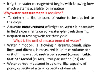
1
Irrigation Water Measurement
Speaker
Dr. Jitendra Sinha, Associate Professor
Department of Soil and Water Engineering,
SVCAETRS, FAE, IGKV, Raipur
jsvenusmars@gmail.com, 7000633581
• Irrigation water management begins with knowing how
much water is available for irrigation
Why water measurement is required?
• To determine the amount of water to be applied to
the crops.
• Accurate measurement of irrigation water is necessary
in field experiments on soil-water-plant relationship.
• Required in testing wells for their yield
What is the unit of measurement of water?
• Water in motion; i.e., flowing in streams, canals, pipe-
lines, and ditches, is measured in units of volume per
unit of time— cubic metre per second (cumec), cubic
feet per second (cusec), litres per second (lps) etc.
• Water at rest: measured in volume; like capacity of
pond, capacity of a tank, capacity of dam etc. 2
1. A Persian wheel discharges at the rate of 11,000 litres per
hour and works for eight hours each day. Estimate the area
commanded by the water lift if the average depth of
irrigation is 8 cm and irrigation interval is 15 days.
Solution:
• The discharge of Persian wheel in 15 days
• =
11,000 × 8 × 15
1000
= 1320 m3
• Water required to cover one hectare to a depth of 8 cm
• = 10,000 ×
8
100
= 800 m3
• Area commanded by Persian wheel
• =
Water available
Water required per unit area
• =
1320
800
= 1.65 hectares.
3
2. Compute the efficiency of an irrigation system based on
the following data: 1800 litres / min of water is diverted to
the farm each day of 24 hrs. Each day 0.8 ha of maize and 1
ha wheat are irrigated. The irrigation requirement of maize is
8 cm and that of wheat 12 cm.
Solution: S = 1800 litres / min =
(1800 × 60 ×24)
1000
= 2592 cubic meters
Volume of water required to irrigate maize
= (
8
100
) × 0.8 × 1000 = 640 cubic meters
Volume of water required to irrigate wheat
= (
12
100
) × 1 × 1000 = 1200 cubic meters
Total water use by maize and wheat
= 640 + 1200 = 1840 cubic meters
• Ei = (
1840
2592
) × 100 = 70.99%, say 71%.
4
• Methods of measuring irrigation water can be
grouped into four basic categories—
1. Direct or volumetric method
2. Velocity-area method
3. Constricted flow
4. Tracer technique
• Choice of method to use will be determined by
the volume of water to be measured, the
degree of accuracy desired, whether the
installation is permanent or temporary, and the
financial investment required.
5
• Direct or Volumetric Measurement Methods
(1) Measuring the period of time required to fill a container of a
known volume can be used to measure small rates of flow such as
from individual siphon tubes, sprinkler nozzles, or from individual
outlets in gated pipe. Ordinarily 20 to 200 litres containers will be
adequate. It is recommended that the measurement be repeated at
least three times and preferably five times to arrive at a reliable rate
of flow per unit of time.
6Source: Irrigation Theory and Practice, AM Michael
2. Velocity-area method : The rate of flow passing
a point in pipe or open channel is determined by
multiplying the cross sectional area of the flow
section at right angles to the direction of flow by
the average velocity of water
Q = A x V
Q = Discharge rate, m3s-1
A = Area of cross section of channel or pipe, m2
V = Velocity of flow, ms-1
7
A. Float method
The float method can be used to obtain an approximate measure of the
rate of flow occurring in an open ditch. It is especially useful where more
expensive installations are not justified or high degree accuracy is not
required.
Select a straight section of ditch from 20 to 30 m long with fairly uniform
cross-sections. Make several measurements of the width and depth of
the test cross-section so as to arrive at an average cross-sectional area.
Using a tape, measure the length of the test section of the ditch. Place a
small floating object in the ditch a few metres above the starting point of
the test section and time the number of seconds for this object to travel
the length of the test section. This time measurement should be made
several times to arrive at a reliable average value. By dividing the length
of the test section (metres) by the average time required (seconds), one
can estimate velocity in metre per second. Since the velocity of water at
the surface is greater than the average velocity of the stream, multiply
the estimated surface velocity by a correction factor (0.80 for smooth
lined ditches, and 0.60 for rough ditches) to obtain the average stream
velocity. To obtain the rate of flow, multiply the average cross sectional
area of the ditch (square metre) times the stream velocity (metres per
second) and the answer is the rate of flow in cubic metres per second.
8
B. Current meter method
The velocity of flow at any point in
the open channel can be most accurately
and conveniently determined by means
of a mechanical device named
current-meter. In the simplest method,
a current meter turns with the
flow of the river or stream. The current
meter is used to measure water
velocity at predetermined points
(subsections) along a marked line,
suspended cableway, or bridge across a river or stream.
The depth of the water is also measured at each point.
Types of current metre:
1. Cup type 2. Pigmy current metre
3. Optical type 4. Curley type
9
1. Cup type current meter
• Also called rotating type
• Flow velocity is proportional to the revolution of the wheel
• No. of revolutions re recorded by an electrical circuit
2. Pigmy type
• Miniature type current metre
• Design and construction similar to curley type current meter
• Most suitable when velocity (< 1 ms-1) and depth of flow are less.
3. Optical current meter
• It is a stroboscopic device used for measuring flow velocity
without immersing into water
• Consists of light weight battery, low power telescope, rotating
mirror, motor and tachometer
4. Curley current meter
• Price current meter
• It consists of head, tail, hanger, recorder and suspended device
10
Rating of current meter:
• Development of a relationship between the number of
revolutions per minute and the flow velocity
• The equation is called rating equation
• Rating equation is provided by the manufacturer
• V = aN + b
V = Velocity of flow (ms-1)
N = Revolutions per second
‘a’ and ‘b’ are constants provided in the rating equation
• Mean velocity is taken as average value associated with 0.2 and
0.8 depth of flow
11
Water meter: These water meters are used to measure the
total flow of water passing
through pipeline in mining,
waterworks and industrial
enterprises.
• It utilises multi blade
Conical propeller made of metal,
Plastic or rubber, rotating in a
Vertical plane and geared to a
totalizer in such manner that a
Numerical counter can
totalise the flow in any desired
volumetric units.
12
Venturi meter
• It measures the flow of water in pipes under pressure
• Based on venturi principle: flow passing through a constricted section of pipe
is accelerated and its pressure head is lowered.
• Discharge can be determined by knowing the cross sectional area and the
pressure drop
13
14
15
16
17
Coordinate Method:
• It measures the jet or water issuing from the end of the pipe
for calculating rate of discharge. Flow from pipes may be
measured whether the pipe is discharging vertically upward,
horizontally or at some angle with the horizontal. Coordinate
methods are used to measure the flow from small pumping
plants discharging horizontally and from flowing wells
discharging vertically. These methods have limited accuracy
owing to problems in making accurate measurements of
coordinate of the jet.
• To measure the flow from pipes discharging vertically upward,
it is necessary to measure inside dia D of the pipe and the
height H of the jet above the pipe outlet .
• To measure the flow from pipes discharging horizontally, it is
necessary to measure both horizontal and vertical distance
from the point on the jet.
• For instance, coordinates are measured from the top of the
inside of the pipe to a point on the top of the jet. These
horizontal and vertical distances are called X and Y ordinates,
respectively. 18
19
• The formula used is obtained by combining the
following equations:
• Q = A × V
• X = V × t or V = X/t
• Y = ½ × gt2 or t = √2Y/g
• Introducing C, the coefficient of discharge, we
have
• Q = C × A × X × √g/2Y
• The above equation can be written as
• where, Q is in lps, X and Y measured in cm, A in
cm2 and g taken as 980 cm s-1. Discharge can be
obtained from standard tables. 20
21The Tracer Technique
22
23
24
25
26
27
28
29
30
31
32
33
34
35
REFERENCES
• Irrigation:
Theory and Practice: AM Michael
• Reference notes: Course no. AENG 151,
Fundamentals of Soil and Water Conservation
Engineering, ANGRAU
• http://www.agricultureinindia.net/wp-content
Be Indian
Buy Indian
38
?
THANK YOU

Irrigation water measurement technique

  • 1.
    1 Irrigation Water Measurement Speaker Dr.Jitendra Sinha, Associate Professor Department of Soil and Water Engineering, SVCAETRS, FAE, IGKV, Raipur jsvenusmars@gmail.com, 7000633581
  • 2.
    • Irrigation watermanagement begins with knowing how much water is available for irrigation Why water measurement is required? • To determine the amount of water to be applied to the crops. • Accurate measurement of irrigation water is necessary in field experiments on soil-water-plant relationship. • Required in testing wells for their yield What is the unit of measurement of water? • Water in motion; i.e., flowing in streams, canals, pipe- lines, and ditches, is measured in units of volume per unit of time— cubic metre per second (cumec), cubic feet per second (cusec), litres per second (lps) etc. • Water at rest: measured in volume; like capacity of pond, capacity of a tank, capacity of dam etc. 2
  • 3.
    1. A Persianwheel discharges at the rate of 11,000 litres per hour and works for eight hours each day. Estimate the area commanded by the water lift if the average depth of irrigation is 8 cm and irrigation interval is 15 days. Solution: • The discharge of Persian wheel in 15 days • = 11,000 × 8 × 15 1000 = 1320 m3 • Water required to cover one hectare to a depth of 8 cm • = 10,000 × 8 100 = 800 m3 • Area commanded by Persian wheel • = Water available Water required per unit area • = 1320 800 = 1.65 hectares. 3
  • 4.
    2. Compute theefficiency of an irrigation system based on the following data: 1800 litres / min of water is diverted to the farm each day of 24 hrs. Each day 0.8 ha of maize and 1 ha wheat are irrigated. The irrigation requirement of maize is 8 cm and that of wheat 12 cm. Solution: S = 1800 litres / min = (1800 × 60 ×24) 1000 = 2592 cubic meters Volume of water required to irrigate maize = ( 8 100 ) × 0.8 × 1000 = 640 cubic meters Volume of water required to irrigate wheat = ( 12 100 ) × 1 × 1000 = 1200 cubic meters Total water use by maize and wheat = 640 + 1200 = 1840 cubic meters • Ei = ( 1840 2592 ) × 100 = 70.99%, say 71%. 4
  • 5.
    • Methods ofmeasuring irrigation water can be grouped into four basic categories— 1. Direct or volumetric method 2. Velocity-area method 3. Constricted flow 4. Tracer technique • Choice of method to use will be determined by the volume of water to be measured, the degree of accuracy desired, whether the installation is permanent or temporary, and the financial investment required. 5
  • 6.
    • Direct orVolumetric Measurement Methods (1) Measuring the period of time required to fill a container of a known volume can be used to measure small rates of flow such as from individual siphon tubes, sprinkler nozzles, or from individual outlets in gated pipe. Ordinarily 20 to 200 litres containers will be adequate. It is recommended that the measurement be repeated at least three times and preferably five times to arrive at a reliable rate of flow per unit of time. 6Source: Irrigation Theory and Practice, AM Michael
  • 7.
    2. Velocity-area method: The rate of flow passing a point in pipe or open channel is determined by multiplying the cross sectional area of the flow section at right angles to the direction of flow by the average velocity of water Q = A x V Q = Discharge rate, m3s-1 A = Area of cross section of channel or pipe, m2 V = Velocity of flow, ms-1 7
  • 8.
    A. Float method Thefloat method can be used to obtain an approximate measure of the rate of flow occurring in an open ditch. It is especially useful where more expensive installations are not justified or high degree accuracy is not required. Select a straight section of ditch from 20 to 30 m long with fairly uniform cross-sections. Make several measurements of the width and depth of the test cross-section so as to arrive at an average cross-sectional area. Using a tape, measure the length of the test section of the ditch. Place a small floating object in the ditch a few metres above the starting point of the test section and time the number of seconds for this object to travel the length of the test section. This time measurement should be made several times to arrive at a reliable average value. By dividing the length of the test section (metres) by the average time required (seconds), one can estimate velocity in metre per second. Since the velocity of water at the surface is greater than the average velocity of the stream, multiply the estimated surface velocity by a correction factor (0.80 for smooth lined ditches, and 0.60 for rough ditches) to obtain the average stream velocity. To obtain the rate of flow, multiply the average cross sectional area of the ditch (square metre) times the stream velocity (metres per second) and the answer is the rate of flow in cubic metres per second. 8
  • 9.
    B. Current metermethod The velocity of flow at any point in the open channel can be most accurately and conveniently determined by means of a mechanical device named current-meter. In the simplest method, a current meter turns with the flow of the river or stream. The current meter is used to measure water velocity at predetermined points (subsections) along a marked line, suspended cableway, or bridge across a river or stream. The depth of the water is also measured at each point. Types of current metre: 1. Cup type 2. Pigmy current metre 3. Optical type 4. Curley type 9
  • 10.
    1. Cup typecurrent meter • Also called rotating type • Flow velocity is proportional to the revolution of the wheel • No. of revolutions re recorded by an electrical circuit 2. Pigmy type • Miniature type current metre • Design and construction similar to curley type current meter • Most suitable when velocity (< 1 ms-1) and depth of flow are less. 3. Optical current meter • It is a stroboscopic device used for measuring flow velocity without immersing into water • Consists of light weight battery, low power telescope, rotating mirror, motor and tachometer 4. Curley current meter • Price current meter • It consists of head, tail, hanger, recorder and suspended device 10
  • 11.
    Rating of currentmeter: • Development of a relationship between the number of revolutions per minute and the flow velocity • The equation is called rating equation • Rating equation is provided by the manufacturer • V = aN + b V = Velocity of flow (ms-1) N = Revolutions per second ‘a’ and ‘b’ are constants provided in the rating equation • Mean velocity is taken as average value associated with 0.2 and 0.8 depth of flow 11
  • 12.
    Water meter: Thesewater meters are used to measure the total flow of water passing through pipeline in mining, waterworks and industrial enterprises. • It utilises multi blade Conical propeller made of metal, Plastic or rubber, rotating in a Vertical plane and geared to a totalizer in such manner that a Numerical counter can totalise the flow in any desired volumetric units. 12
  • 13.
    Venturi meter • Itmeasures the flow of water in pipes under pressure • Based on venturi principle: flow passing through a constricted section of pipe is accelerated and its pressure head is lowered. • Discharge can be determined by knowing the cross sectional area and the pressure drop 13
  • 14.
  • 15.
  • 16.
  • 17.
  • 18.
    Coordinate Method: • Itmeasures the jet or water issuing from the end of the pipe for calculating rate of discharge. Flow from pipes may be measured whether the pipe is discharging vertically upward, horizontally or at some angle with the horizontal. Coordinate methods are used to measure the flow from small pumping plants discharging horizontally and from flowing wells discharging vertically. These methods have limited accuracy owing to problems in making accurate measurements of coordinate of the jet. • To measure the flow from pipes discharging vertically upward, it is necessary to measure inside dia D of the pipe and the height H of the jet above the pipe outlet . • To measure the flow from pipes discharging horizontally, it is necessary to measure both horizontal and vertical distance from the point on the jet. • For instance, coordinates are measured from the top of the inside of the pipe to a point on the top of the jet. These horizontal and vertical distances are called X and Y ordinates, respectively. 18
  • 19.
  • 20.
    • The formulaused is obtained by combining the following equations: • Q = A × V • X = V × t or V = X/t • Y = ½ × gt2 or t = √2Y/g • Introducing C, the coefficient of discharge, we have • Q = C × A × X × √g/2Y • The above equation can be written as • where, Q is in lps, X and Y measured in cm, A in cm2 and g taken as 980 cm s-1. Discharge can be obtained from standard tables. 20
  • 21.
  • 22.
  • 23.
  • 24.
  • 25.
  • 26.
  • 27.
  • 28.
  • 29.
  • 30.
  • 31.
  • 32.
  • 33.
  • 34.
  • 35.
  • 36.
    REFERENCES • Irrigation: Theory andPractice: AM Michael • Reference notes: Course no. AENG 151, Fundamentals of Soil and Water Conservation Engineering, ANGRAU • http://www.agricultureinindia.net/wp-content
  • 37.
  • 38.