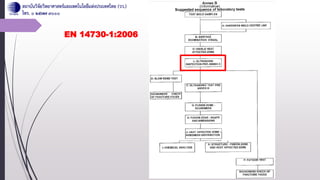
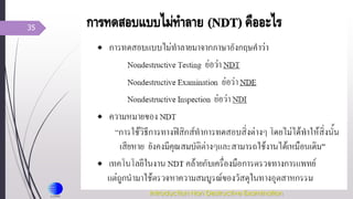
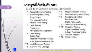
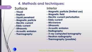
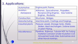
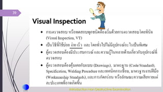
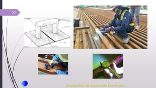
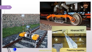
1) The document discusses principles and standards of non-destructive testing (NDT) for railway inspection. It covers various NDT methods including visual inspection, magnetic particle testing, ultrasonic testing, and radiographic testing.
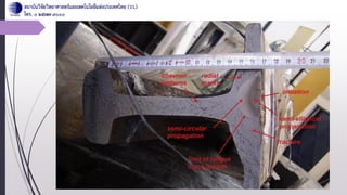
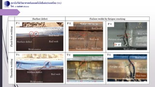
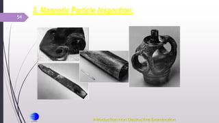
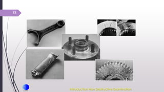
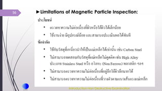
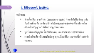
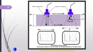
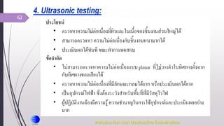
2) Specific NDT techniques are described for inspecting different types of railway components and defects. Magnetic particle testing is used to detect surface cracks in metal parts. Ultrasonic testing employs high frequency sound waves to inspect the internal structure of rails.
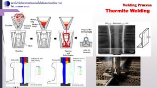
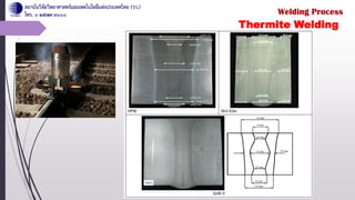
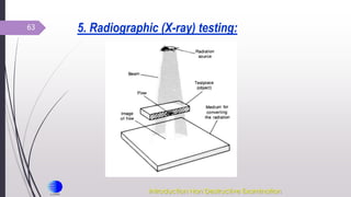
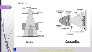
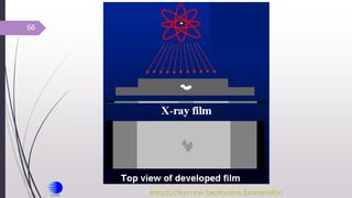
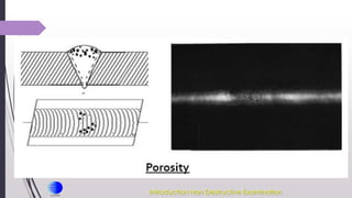
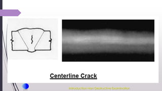
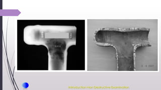
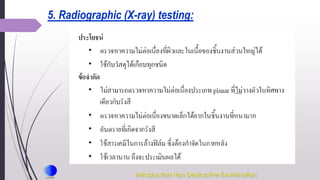
3) Radiographic testing utilizes X-rays to examine welds and internal flaws in thick sections. Together, these NDT methods allow comprehensive inspection of rails, wheels, and other critical components to ensure safety and performance of railway