Downloaded 566 times
![Heat Rate
HEAT RATE – Kilo Calories input to TURBNE divided by
Gross generation in KW [K.Cal/KWH]
[Gross TG Heat Rate = ((Main Steam Flow at Turbine inlet x
(Main Steam Enthalpy – Feed water Enthalpy at Eco-inlet))
+ (CRH Steam Flow x (HRH Steam Enthalpy - CRH
Enthalpy)) + (ReHeat Spray Flow x (HRH Steam Enthalpy -
Feed water Enthalpy at Eco-inlet)) / Gross Generation
Gross TG Heat Rate =
{(Main Steam Flow at Turbine inlet x
(Main Steam Enthalpy – Feed water Enthalpy at Eco-inlet)}
/ Gross Generation
17](https://image.slidesharecdn.com/01regenerativefeedheating-140814065404-phpapp02/85/01-regenerative-feed-heating-17-320.jpg)
![27
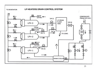
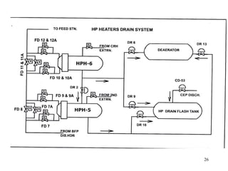
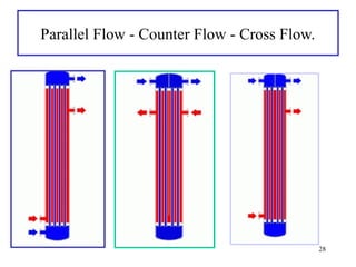
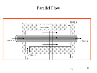
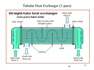
HEAT EXCHANGERS
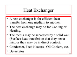
Heat Exchangers may be of two types –
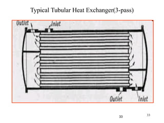
1] Surface Type –Tubular or Plate Type.-Fluids do not
mix.
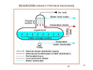
2] Contact Type.-Hot & Cold fluids mix.
Regenerative feed heaters are all tubular surface type
except the De-aerator.
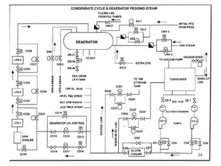
De-aerator is a contact type Heat Exchanger where HOT
and COLD fluids mix.
Plate type are used for cooling of BCW. These are
suitable for low pressure & low temperature applications.
27](https://image.slidesharecdn.com/01regenerativefeedheating-140814065404-phpapp02/85/01-regenerative-feed-heating-27-320.jpg)
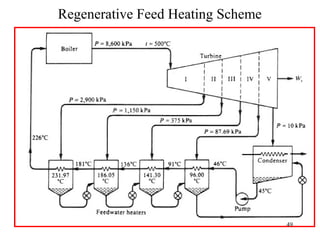
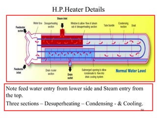
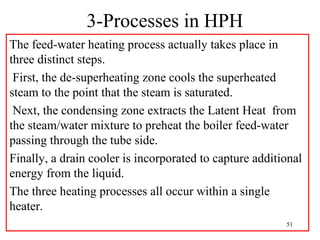
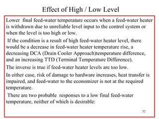
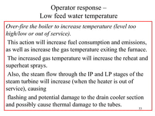


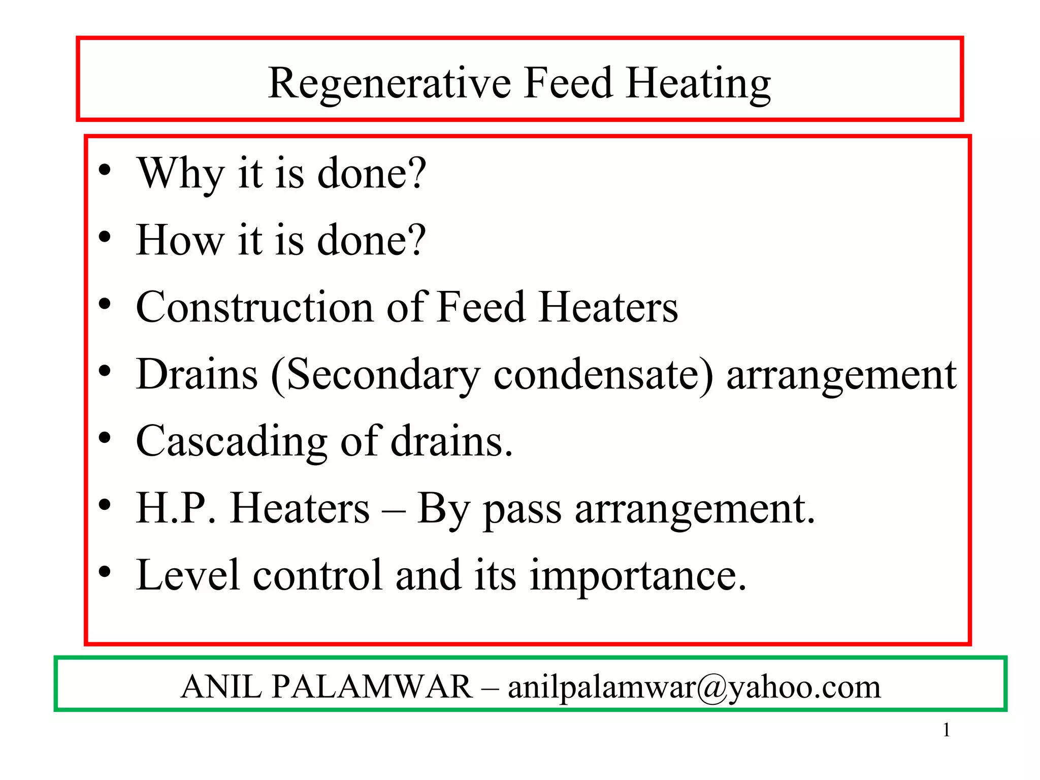
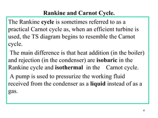
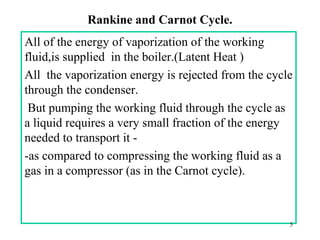
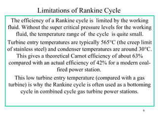
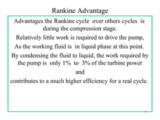
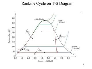
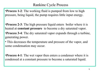
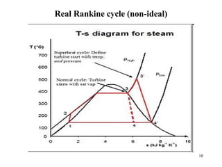
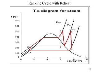
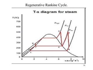
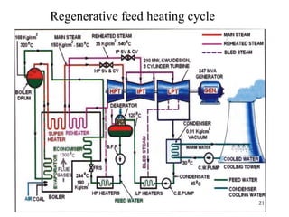
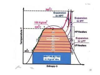
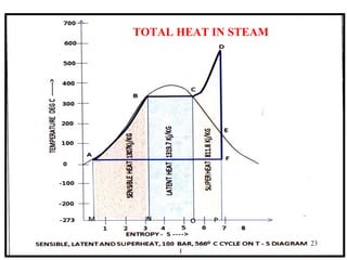
The document discusses the regenerative Rankine cycle, explaining its structure and advantages in improving thermal efficiency of power plants through features like feed water heating and reheat processes. It covers the importance of maintaining optimal feed water temperatures and the consequences of poor level control in feed water heaters, leading to efficiency loss and increased operational costs. Additionally, it details heat exchanger designs, their types, and the role of baffles in optimizing heat transfer processes.


