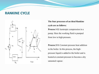
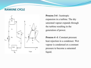
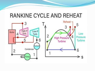
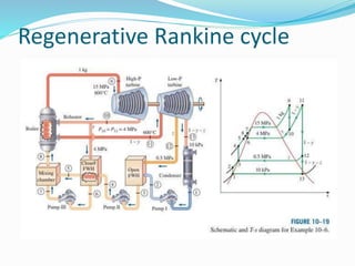
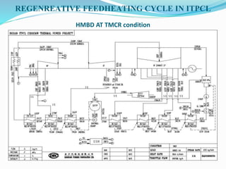
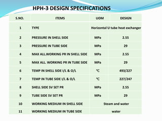
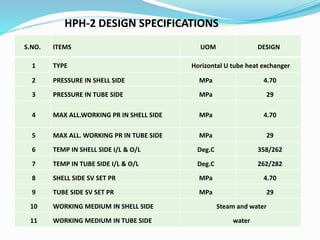
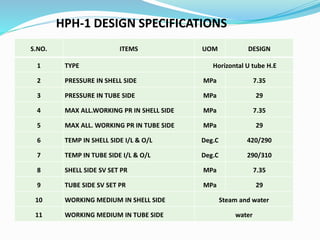
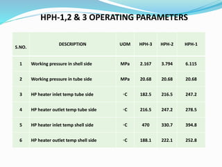
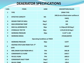
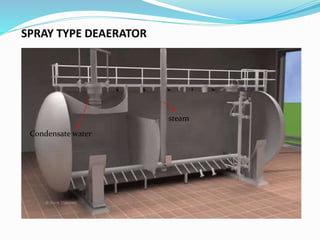
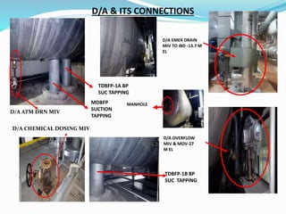
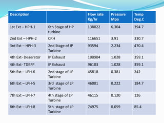
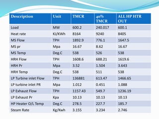
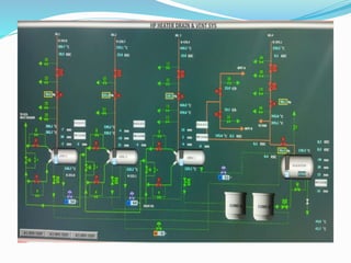
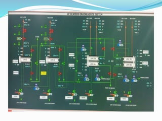
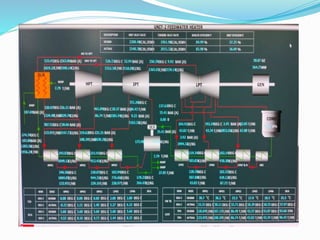
SlideShare a Scribd company logo
1 of 62
REGENERATIVE
FEEDHEATING CYCLE
RATHNABALACHANDAR R K
 WHY IT’S DONE?
 HOW IT’S DONE?
 FEEDWATER HEATERS.
 PERFORMANCE
TO IMPROVE THE EFFICIENCY
 Q= K*A *d T
 Efficiency of heat transfer is maximum when dT tends
to zero.
 By raising the temperature of feed water in stages we
achieve a low dT at every stage.
 Average temperature of at which heat is added also
increases and gives better efficiency.
RANKINE CYCLE
The four processes of an ideal Rankine
cycle are as follows:
Process1-2: Isentropic compression in a
pump. Here the working fluid is pumped
from low to high pressure.
Process2-3: Constant pressure heat addition
in the boiler. In this process, the high-
pressure liquid is added to the boiler and is
heatedat constant pressure to become a dry
saturated vapour.
RANKINE CYCLE
Process 3-4 : Isentropic
expansion in a turbine. The dry
saturated vapour expands through
the turbine resulting in the
generation of power.
Process 4 -1: Constant pressure
heat rejection in a condenser. Wet
vapour is condensed at a constant
pressure to become a saturated
liquid.
Regenerative Rankine cycle
ADVANTAGES
 THERMAL EFFICIENCY INCREASES
 REDUCED STEAM FLOW TO CONDENSER
 DIFFICULTY IN PASSING LARGE VOL OF STEAM
THROUGH LAST STAGE IN LP TURBINE IS REDUCED –
BLADE HEIGHT TOBE INCREASED TO ACCOMMODATE
HIGH SPE.VOL OF STEAM.
 DECREASE IN STEAM FLOW AT TURBINE EXHAUST -
SMALLER CONDENSER , LPH’S, HPH’S.
 REDUCED SIZE RESULTS IN SAVING CAPITAL
INVESTMENT.
WHY FW HEATERS IN POWER PLANT
 Heating the feed Water.
 Increasing the cycle efficiency.
 Reduction in fuel consumption.
DESIGN CODE OF FW HEATERS
 HEI,ASME SEC VIII DIV-1 IBR
FEEDWATER HEATERS
 A feedwater heater is a heat exchanger used to pre-
heat water delivered to steam generating boiler in the
regenerative Feed Heating System.
 Steam is extracted from the steam turbine at various
stage.
 This results in higher cycle efficiency by increasing the
temperature of the feed water and by reducing the
amount of energy lost in the condenser.es and used to
heat the feed water
 Feed-water heaters can be Open and Closed heat
exchangers.
Open heat exchangers.
 An open feedwater heater is a direct-contact heat
exchanger in which extracted steam is allowed to mix
with the feedwater.
 This kind of heater will normally require a feed pump
at both the feed inlet and outlet since the pressure in
the heater is between the boiler pressure and
the condenser pressure.
 A deaerator is a special case of the open feedwater
heater which is specifically designed to remove non-
condensable gases from the feedwater.
Closed heat exchangers.
 Closed feedwater heaters are typically shell and tube
heat exchngers where the feedwater passes throughout
the tubes and is heated by turbine extraction steam.
 These do not require separate pumps before and after
the heater to boost the feedwater to the pressure of the
extracted steam as with an open heater.
ADVANTAGES OF FW HEATERS
 Fuel consumption reduces
 Preheating improves the thermodynamic efficiency of the
system.
 reduces plant operating costs and also helps to avoid thermal
shock to the boiler metal when the feedwater is introduced
back into the steam cycle.
 Reduce heat losses in the condenser
 Lower emissions as fuel use is reduced due to improve heat
rate.
 Decrease the plant heat rate & hence increases the plant
efficiency.
Zones of heaters
 De Superheating Zone.
cools the superheated steam to the point that the
steam is saturated.
 Condensing Zone.
Maximum heat transfer occurs
 Sub Cooling Zone.
Condensed steam cooled by feed water by convective
heat transfer method
Zones of heaters
Pipe lines connected to HP heaters
 Feed water inlet line
 Feed water outlet line
 Condensate outline
 Bleed Steam line ( Extraction steam line)
 Shell Zone Drain & Vent (Operating vent & startup
vent).
 Feed Water box Drain & vent lines.
FEED WATER HEATER PERFORMANCE
Three Variables are used to monitor feed water
heaters efficiency.
•Heater TTD or Terminal temp Difference.
•Heater DCA or Drain Cooler Approach.
•Feed Water heater Temp rise= TFWO-TFWI.
TTD OR TERMINAL TEMP DIFFERENCE
 Difference between the saturation temperature at the
operating pressure of the inlet steam to the heater and
the temperature of the feed water leaving the heater.
 For more cycle efficiency TTD value should be more.
 An increase in TTD indicates a reduction in heat transfer
while a decrease is an improvement.
 For the best performance , heaters are designed to get
TTD 3 to 5 Deg.C at full operating capacity.
 TTD = TSAT - TFWO
High TTD indicates:
 Excessive venting (worn vents, altered set point, vent
malfunctioning)
 Excessive make up
 High water level (tube leaks, improper setting)
 Non condensable gases on shell side
 Excessive tube bundle pressure drop (excessive
number of tubes plugged, tubes folded internally)
DCA OR DRAIN COOLER APPROCAH
 Heater DCA how close the drain outlet temp to feed water inlet
temperature
 DCA infers the condensate levels present within a feed water heater.
 An increasing DCA temperature difference indicates the level is
decreasing. severe damage to the tubes and other internals such as
plates and baffles.
 Decreasing DCA indicates a rise in level, good for Drain Cooling zone.
 DCA high, corrective action to restoring the water level to proper
range from a level that is too low.
 DCA= TDCO - TFWI
High DCA temperature indicates:
 Drain cooler inlet not submerged
 Low drain water level (improper setting, excessive FW
heater drain bypass – bypass valve left open - bypass
valve malfunctioning / leaking)
 Excessive tube bundle pressure drop (excessive
number of tubes plugged / tubes folded internally)
 Feed water heater bypassed
 FW heater bypass valve leaking
 FEED-WATER TEMPERATURE RISE (TR) is the
difference between the feed-water outlet temperature
and the feed-water inlet temperature. A properly
performing heater should meet the manufacturer’s
design specifications, provided the level controls are
up to the task.
TR = Tout – Tin
 Tin = saturation temperature of the extraction steam
 Tout = feed-water outlet temperature
Level of heaters.
 Higher the condensate level is lower the performance
of heater & vice versa
 Heater level is always maintained between 30-50%.
FEED WATER HEATER IMPACT ON THERMAL
PERFORMANCE
 1 Deg.C in TTD, 0.033% increase in heat rate.
 1 Deg.C in DCA,0.01% increase in heat rate.
 Increasing TTD & DCA cause increased heat rate and reduced
electrical output.
FW HEATER RESPONSES
PROBLEM TR TTD DCA
Inadequate Vent Decrease Increase Increase
Level increase Decrease Increase Decrease
Level Decrease Increase Decrease Increase
Tube Fouling Decrease Increase Increase
Tube Leak Decrease Increase Increase
High FW Flow Decrease Increase Increase
Plugged Tubes Decrease Increase Increase
DEAERATOR
 Deaerator removes dissolved gases mainly dissolved oxygen
and other non-condensable gases from boiler feed water.
 Dissolved Oxygen causes pitting type corrosion in feed
water systems.
DEAERATION PROCESS
 Mechanical Deaeration
 Chemical Deaeration
DEAERATOR
Mechanical Deaeration
 Water is heated by steam within a few degree of its saturation temperature
according to deaerator operating pressure.
 Approx. 97-98% of dissolved gases released with the steam & escaped from
the vents of deaerator.
Chemical Deaeration
 Remainder 2-3% of dissolved gases removed by scrubbing the water with the
steam & addition of oxygen scavenger chemicals.
N2H4 + O2 → N2 + 2H2O
 Venting is critical and necessary for the effective removal of dissolved gases
like oxygen and other non-condensable gases such as carbon dioxide.
DEAERATOR
Why steam is used as a purge gas in deaerator?
 It doesn’t contaminate the water.
 Only a small quantity of steam is venting from deaerator.
 Most of the steam condenses and becomes the part of
deaerator water.
 It heats the boiler feed water up to the saturation
temperature, so that solubility of unwanted dissolved gases
are decreases.
DEAERATOR
Steam Sources & Lines Connected in Deaerator:
• Auxiliary steam header.
• Extraction Steam (normally 4th).
• CRH.
• Heaters Normal drain.
• Heaters Operating vent.
• Vents.
• Condensate water (LP Heater Outlet).
REGENREATIVE FEEDHEATING CYCLE IN ITPCL
HMBD AT TMCR condition
LP HEATERS
 There are 4*100% capacity, horizontal type, U-type LP heaters
equipped.
 Designated as LP Heater -8A/7A > LP Heater 8B/7B > LP Heater -
6 >LP heater-5 respectively in the order along the direction of
water flow.
Types of Feed water heaters
LPH-5 DESIGN SPECIFICATIONS
S.NO. ITEMS UOM DESIGN
1 TYPE Horizontal U tube heat exchanger
2 PRESSURE IN SHELL SIDE MPa 0.6
3 PRESSURE IN TUBE SIDE MPa 4.2
4 MAX ALL.WORKING PR IN SHELL SIDE MPa 0.612
5 MAX ALL. WORKING PR IN TUBE SIDE MPa 4.28
6 TEMP IN SHELL SIDE I/L & O/L ℃ 242/124.8
7 TEMP IN TUBE SIDE I/L & O/L ℃ 119.2/137.3
8 SHELL SIDE SV SET PR MPa 0.6
9 TUBE SIDE SV SET PR MPa 4.2
10 WORKING MEDIUM IN SHELL SIDE Steam and water
11 WORKING MEDIUM IN TUBE SIDE Condensate water
Types of Feed water heaters
LPH-6 DESIGN SPECIFICATIONS
S.NO. ITEMS UOM DESIGN
1 TYPE Horizontal U tube heat exchanger
2 PRESSURE IN SHELL SIDE MPa 0.6
3 PRESSURE IN TUBE SIDE MPa 4.2
4 MAX ALL.WORKING PR IN SHELL SIDE MPa 0.612 @150 ℃
5 MAX ALL. WORKING PR IN TUBE SIDE MPa 4.28 @ 150 ℃
6 TEMP IN SHELL SIDE I/L & O/L ℃ 1874.7/106.1
7 TEMP IN TUBE SIDE I/L & O/L ℃ 100.5/119.2
8 SHELL SIDE SV SET PR MPa 0.6
9 TUBE SIDE SV SET PR MPa 4.2
10 WORKING MEDIUM IN SHELL SIDE Steam and water
11 WORKING MEDIUM IN TUBE SIDE Condensate water
Types of Feed water heaters
LPH-7A & 7B DESIGN SPECIFICATIONS
S.NO. ITEMS UOM DESIGN
1 TYPE Horizontal U tube heat exchanger
2 PRESSURE IN SHELL SIDE MPa 0.6
3 PRESSURE IN TUBE SIDE MPa 4.2
4 MAX ALL.WORKING PR IN SHELL SIDE MPa 0.612 @ 150 ℃
5 MAX ALL. WORKING PR IN TUBE SIDE MPa 4.28 @ 150 ℃
6 TEMP IN SHELL SIDE I/L & O/L ℃ 126/86.9
7 TEMP IN TUBE SIDE I/L & O/L ℃ 81.3/100.5
8 SHELL SIDE SV SET PR MPa 0.6
9 TUBE SIDE SV SET PR MPa 4.2
10 WORKING MEDIUM IN SHELL SIDE Steam and water
11 WORKING MEDIUM IN TUBE SIDE Condensate water
LPH-8A & 8B DESIGN SPECIFICATIONS
S.NO. ITEMS UOM DESIGN
1 TYPE Horizontal U tube heat exchanger
2 PRESSURE IN SHELL SIDE MPa 0.6
3 PRESSURE IN TUBE SIDE MPa 4.2
4 MAX ALL.WORKING PR IN SHELL SIDE MPa 0.612 @ 150 ℃
5 MAX ALL. WORKING PR IN TUBE SIDE MPa 4.28 @ 150 ℃
6 TEMP IN SHELL SIDE I/L & O/L ℃ 85.4/52.9
7 TEMP IN TUBE SIDE I/L & O/L ℃ 47.3/81.3
8 SHELL SIDE SV SET PR MPa 0.6
9 TUBE SIDE SV SET PR MPa 4.2
10 WORKING MEDIUM IN SHELL SIDE Steam and water
11 WORKING MEDIUM IN TUBE SIDE Condensate water
HP HEATERS
 There are 3*100% capacity, horizontal type, U-type LP heaters
equipped.
 Designated as HP Heater-3 > HP Heater-2 > HP Heater-1
respectively in the order along the direction of water flow.
HPH-3 DESIGN SPECIFICATIONS
S.NO. ITEMS UOM DESIGN
1 TYPE Horizontal U tube heat exchanger
2 PRESSURE IN SHELL SIDE MPa 2.55
3 PRESSURE IN TUBE SIDE MPa 29
4 MAX ALL.WORKING PR IN SHELL SIDE MPa 2.55
5 MAX ALL. WORKING PR IN TUBE SIDE MPa 29
6 TEMP IN SHELL SIDE I/L & O/L ℃ 493/227
7 TEMP IN TUBE SIDE I/L & O/L ℃ 227/247
8 SHELL SIDE SV SET PR MPa 2.55
9 TUBE SIDE SV SET PR MPa 29
10 WORKING MEDIUM IN SHELL SIDE Steam and water
11 WORKING MEDIUM IN TUBE SIDE water
HPH-2 DESIGN SPECIFICATIONS
S.NO. ITEMS UOM DESIGN
1 TYPE Horizontal U tube heat exchanger
2 PRESSURE IN SHELL SIDE MPa 4.70
3 PRESSURE IN TUBE SIDE MPa 29
4 MAX ALL.WORKING PR IN SHELL SIDE MPa 4.70
5 MAX ALL. WORKING PR IN TUBE SIDE MPa 29
6 TEMP IN SHELL SIDE I/L & O/L Deg.C 358/262
7 TEMP IN TUBE SIDE I/L & O/L Deg.C 262/282
8 SHELL SIDE SV SET PR MPa 4.70
9 TUBE SIDE SV SET PR MPa 29
10 WORKING MEDIUM IN SHELL SIDE Steam and water
11 WORKING MEDIUM IN TUBE SIDE water
HPH-1 DESIGN SPECIFICATIONS
S.NO. ITEMS UOM DESIGN
1 TYPE Horizontal U tube H.E
2 PRESSURE IN SHELL SIDE MPa 7.35
3 PRESSURE IN TUBE SIDE MPa 29
4 MAX ALL.WORKING PR IN SHELL SIDE MPa 7.35
5 MAX ALL. WORKING PR IN TUBE SIDE MPa 29
6 TEMP IN SHELL SIDE I/L & O/L Deg.C 420/290
7 TEMP IN TUBE SIDE I/L & O/L Deg.C 290/310
8 SHELL SIDE SV SET PR MPa 7.35
9 TUBE SIDE SV SET PR MPa 29
10 WORKING MEDIUM IN SHELL SIDE Steam and water
11 WORKING MEDIUM IN TUBE SIDE water
HPH-1,2 & 3 OPERATING PARAMETERS
S.NO.
DESCRIPTION UOM HPH-3 HPH-2 HPH-1
1 Working pressure in shell side MPa 2.167 3.794 6.115
2 Working pressure in tube side MPa 20.68 20.68 20.68
3 HP heater inlet temp tube side ◦C 182.5 216.5 247.2
4 HP heater outlet temp tube side ◦C 216.5 247.2 278.5
5 HP heater inlet temp shell side ◦C 470 330.7 394.8
6 HP heater outlet temp shell side ◦C 188.1 222.1 252.8
HPH-1 I/L & O/L Valve HPH-1 Bypass Valve
HPH-2 INLET VALVE
HPH-2 BYPASS VALVE
HPH-2 O/L VALVE
HPH-3 INLET VALVE
HPH-3 BYPASS VALVE
HPH-3 O/L VALVE
HPH-1 I/L HDR DRAIN MIV
HPH-2 I/L HDR DRAIN MIV
HPH-3 INLET HDR DRAIN MIV
LOCATION-6.9 M
Problems in FW Heaters
 Flashing in heaters
change in state of liquid to vapour.
o If the liquid drains are not sub cooled enough , any one
of these pressure drops could result in flashing and
two phase flow.
o Two phase flow is known to cause problems to piping ,
tubing, the cage& the shell.
Fouling
 Deposition of any undesired material on heat transfer
surfaces.
 Impact the thermal & mechanical performance of heat
exchangers.
 Increases the thermal resistance & lowers the heat
transfer coefficient of heat exchangers.
 Impedes the fluid flow , accelerates corrosion &
increase the pressure drop across heat Exchangers.
 Particulate / Sedimentation Fouling, Corrosion fouling
, Chemical Fouling & Freezing Fouling.
Fouling
 Initial Two phase Mixture & Hammering.
 Tubes Failure Due to Wrong Operation.
 Level Fluctuation & Leakages.
 Overfeeding of steam& Feed water
 Operating the heaters above the parameters & design
parameters.
Precautions
 Operate the LP& HP Heaters as per SOP.
 Take Utmost Caring during initial charging.
 Do not operate the heaters beyond the operating
pressure & temperature.
 Conduct routine preventive maintenance.
 Bypass the LP & HP heaters Boilers Hydraulic tests.
PROBABLE REASONS RECOMMENDED MEASURES
Air blanketing of Tubes due to
insufficient venting.
Ensure proper venting and check for
the tube leakage, if any.
Deviations in operating flow
conditions and other process
parameters.
Maintain flow and other parameters
within their design limits
Excessive level build- up resulting in
the submergence of parts of tubes,
which will
reduce available heat transfer area.
Maintain liquid level within the
normal limits
Fouling of the Tube surface Periodic inspection & proper cleaning
of the tubes.
REASONS FOR REDUCTION IN FEED WATER HEATER
PERFORMANCE
FUNCTION OF DEAERATOR
Extraction from:
Auxiliary Steam Header & 4th extraction.
Function:-
 As Feed Water Storage Tank
 As Feed Heater( Direct Mixing Type)
 To Provide NPSH to BFP
 AS Deaerator (To remove Dissolved O2,CO2 which is harmful to the System
due to its corrosive attack on the metal).
 The vendors of deaerators usually gives guarantee of less than 7 ppb of
dissolved oxygen in boiler feed water.
DEAERATOR SPECIFICATIONS
S.NO. ITEMS UOM DESCRIPTION/VALUES
1 TYPE SPRAY TYPE
2 EFFECTIVE CAPACITY M3
240 (6 min of feed water outflow at
VWO)
3 DESIGN TEMP OF SHELL Deg.C 220
4 MAX OPERATING TEMP Deg.C 182
5 MAX ALL.WORKING PR Mpa 1.3 Mpa @ 220 Deg.C
6 HYDRAULIC TEST PR Mpa 1.95 @ 20-50 Deg.C
7 WORKING PRESSURE Mpa 0.147~1.105
8 WORKING MEDIA STEAM,WATER
Operating Conditions at TMCR
1 WORKING PRESSURE Mpa 0.977
2
HEATING STM FLOW FROM TUR 4TH
EXTR
TPH 100.87
3 NML DRAIN FLOW FROM HPH-3 TPH 348.28
4 CONDENSATE I/L FLOW TPH 1443.7
5 FW O/L FLOW TPH 1892.9
6 CONDENSATE INLET TEMP Deg.C 137.3
7 FW O/L TEMP Deg.C 178.9
SPRAY TYPE DEAERATOR
Condensate water
steam
D/A & ITS CONNECTIONS
D/A EMER DRAIN
MIV TO IBD -13.7 M
EL
D/A OVERFLOW
MIV & MOV-27
M EL
D/A ATM DRN MIV
D/A CHEMICAL DOSING MIV
MDBFP
SUCTION
TAPPING
TDBFP-1A BP
SUC TAPPING
TDBFP-1B BP
SUC TAPPING
MANHOLE
Description Flow rate
Kg/hr
Pressure
Mpa
Temp
Deg.C
1st Ext – HPH-1 6th Stage of HP
turbine
138022 6.304 394.7
2nd Ext – HPH-2 CRH 116651 3.91 330.7
3rd Ext – HPH-3 2nd Stage of IP
Turbine
93594 2.234 470.4
4th Ext- Deaerator IP Exhaust 100904 1.028 359.1
4th Ext- TDBFP IP Exhaust 96103 1.028 359.1
5th Ext – LPH-6 2nd stage of LP
Turbine
45818 0.381 242
6th Ext – LPH-5 3rd stage of LP
Turbine
46001 0.222 184.7
7th Ext – LPH-7 4th stage of LP
Turbine
46115 0.120 126
8th Ext – LPH-8 5th stage of LP
Turbine
74975 0.059 85.4
Description Unit TMCR 40%
TMCR
ALL HP HTR
OUT
Load MW 600.2 240.017 600.1
Heat rate KJ/KWh 8164 9240 8405
MS Flow TPH 1892.9 776.1 1647.5
MS pr Mpa 16.67 8.62 16.67
MS Temp Deg.C 538 526 538
HRH Flow TPH 1608.6 688.21 1619.6
HRH Pr Mpa 3.52 1.504 3.643
HRH Temp Deg.C 538 511 538
LP Turbine inlet Flow TPH 136881 613.47 1466.65
LP turbine inlet PR Mpa 1.012 0.451 1.088
LP Exhaust Flow TPH 1157.43 549.7 1236.19
LP Exhaust Pr Kpa 10.13 10.13 10.13
HP Heater O/L Temp Deg.C 278.5 227.7 185.7
Steam Rate Kg/Kwh 3.155 3.234 2.746
THANK YOU
DEAERATOR
 Henry’s Law (scrubbing with oxygen free steam):
The amount of dissolved gases present in
water is directly proportional to the partial pressure of
that gas in the vapour space above the water/gas
interface.
 Charles’Law (oxygen solubility vs temperature):
The solubility of oxygen decreases as
the temperature of water increases.

More Related Content

Similar to REGENERATIVE FEEDHEATING.pptx

So603 b incineration plant
So603 b incineration plantSo603 b incineration plant
So603 b incineration plantRavi Jethra
 
2013edusat lecture on steam plant(2)
2013edusat lecture on steam  plant(2)2013edusat lecture on steam  plant(2)
2013edusat lecture on steam plant(2)iimt college meerut
 
Steam Power Plant and Rankine Cycles
Steam Power Plant and Rankine CyclesSteam Power Plant and Rankine Cycles
Steam Power Plant and Rankine CyclesRidwanul Hoque
 
Desuperheater selection guide
Desuperheater selection guideDesuperheater selection guide
Desuperheater selection guideshwetashivankar17
 
Steam Generators - SNIST (M.Tech)
Steam Generators - SNIST (M.Tech)Steam Generators - SNIST (M.Tech)
Steam Generators - SNIST (M.Tech)S.Vijaya Bhaskar
 
A STUDY ON ROLE OF CONDENSER AND NATURAL DRAFT COOLING TOWER ON THE PERFORMAN...
A STUDY ON ROLE OF CONDENSER AND NATURAL DRAFT COOLING TOWER ON THE PERFORMAN...A STUDY ON ROLE OF CONDENSER AND NATURAL DRAFT COOLING TOWER ON THE PERFORMAN...
A STUDY ON ROLE OF CONDENSER AND NATURAL DRAFT COOLING TOWER ON THE PERFORMAN...Saikat Halder
 
Steam_Boiler_Basics_tim_powell_hughes.pdf
Steam_Boiler_Basics_tim_powell_hughes.pdfSteam_Boiler_Basics_tim_powell_hughes.pdf
Steam_Boiler_Basics_tim_powell_hughes.pdfGaluhAjeng26
 
Performance calculation for feed water heater
Performance calculation  for feed water heaterPerformance calculation  for feed water heater
Performance calculation for feed water heaterSHIVAJI CHOUDHURY
 
Rankine Cycle & How to increase its efficiency
Rankine Cycle & How to increase its efficiencyRankine Cycle & How to increase its efficiency
Rankine Cycle & How to increase its efficiencyRaja Dolat
 
Panipat thermal power station training ppt
Panipat thermal power station training pptPanipat thermal power station training ppt
Panipat thermal power station training pptMohit Verma
 
BLUEWAY Air cooled water chiller Brochure
BLUEWAY Air cooled water chiller BrochureBLUEWAY Air cooled water chiller Brochure
BLUEWAY Air cooled water chiller BrochureRoger Luo
 
Theoretical analysis of the performance of dual pressure condenser in a therm...
Theoretical analysis of the performance of dual pressure condenser in a therm...Theoretical analysis of the performance of dual pressure condenser in a therm...
Theoretical analysis of the performance of dual pressure condenser in a therm...IAEME Publication
 
vapour-power-cycle h.pptx
vapour-power-cycle                          h.pptxvapour-power-cycle                          h.pptx
vapour-power-cycle h.pptxMahamad Jawhar
 
Load Match Next Generation
Load Match Next GenerationLoad Match Next Generation
Load Match Next Generationkiakaha
 
vapour-power-cycle.pptx
vapour-power-cycle.pptxvapour-power-cycle.pptx
vapour-power-cycle.pptxDhruvBagade
 

Similar to REGENERATIVE FEEDHEATING.pptx (20)

So603 b incineration plant
So603 b incineration plantSo603 b incineration plant
So603 b incineration plant
 
lecture on steam plant
 lecture on steam  plant lecture on steam  plant
lecture on steam plant
 
2013edusat lecture on steam plant(2)
2013edusat lecture on steam  plant(2)2013edusat lecture on steam  plant(2)
2013edusat lecture on steam plant(2)
 
Steam Power Plant and Rankine Cycles
Steam Power Plant and Rankine CyclesSteam Power Plant and Rankine Cycles
Steam Power Plant and Rankine Cycles
 
Desuperheater selection guide
Desuperheater selection guideDesuperheater selection guide
Desuperheater selection guide
 
Steam Generators - SNIST (M.Tech)
Steam Generators - SNIST (M.Tech)Steam Generators - SNIST (M.Tech)
Steam Generators - SNIST (M.Tech)
 
A STUDY ON ROLE OF CONDENSER AND NATURAL DRAFT COOLING TOWER ON THE PERFORMAN...
A STUDY ON ROLE OF CONDENSER AND NATURAL DRAFT COOLING TOWER ON THE PERFORMAN...A STUDY ON ROLE OF CONDENSER AND NATURAL DRAFT COOLING TOWER ON THE PERFORMAN...
A STUDY ON ROLE OF CONDENSER AND NATURAL DRAFT COOLING TOWER ON THE PERFORMAN...
 
Steam_Boiler_Basics_tim_powell_hughes.pdf
Steam_Boiler_Basics_tim_powell_hughes.pdfSteam_Boiler_Basics_tim_powell_hughes.pdf
Steam_Boiler_Basics_tim_powell_hughes.pdf
 
Steam turbine deaerating condenser perforamace improvement
Steam turbine deaerating condenser perforamace improvementSteam turbine deaerating condenser perforamace improvement
Steam turbine deaerating condenser perforamace improvement
 
Performance calculation for feed water heater
Performance calculation  for feed water heaterPerformance calculation  for feed water heater
Performance calculation for feed water heater
 
Rankine Cycle & How to increase its efficiency
Rankine Cycle & How to increase its efficiencyRankine Cycle & How to increase its efficiency
Rankine Cycle & How to increase its efficiency
 
Panipat thermal power station training ppt
Panipat thermal power station training pptPanipat thermal power station training ppt
Panipat thermal power station training ppt
 
BLUEWAY Air cooled water chiller Brochure
BLUEWAY Air cooled water chiller BrochureBLUEWAY Air cooled water chiller Brochure
BLUEWAY Air cooled water chiller Brochure
 
Theoretical analysis of the performance of dual pressure condenser in a therm...
Theoretical analysis of the performance of dual pressure condenser in a therm...Theoretical analysis of the performance of dual pressure condenser in a therm...
Theoretical analysis of the performance of dual pressure condenser in a therm...
 
Theoretical analysis of the performance of dual pressure condenser in a therm...
Theoretical analysis of the performance of dual pressure condenser in a therm...Theoretical analysis of the performance of dual pressure condenser in a therm...
Theoretical analysis of the performance of dual pressure condenser in a therm...
 
vapour-power-cycle h.pptx
vapour-power-cycle                          h.pptxvapour-power-cycle                          h.pptx
vapour-power-cycle h.pptx
 
Load Match Next Generation
Load Match Next GenerationLoad Match Next Generation
Load Match Next Generation
 
vapour-power-cycle.pptx
vapour-power-cycle.pptxvapour-power-cycle.pptx
vapour-power-cycle.pptx
 
Steam condensers
Steam condensersSteam condensers
Steam condensers
 
Thermal power plant
Thermal power plantThermal power plant
Thermal power plant
 

More from ssuser28a1a31

Dearator level control auto loop.pptx
Dearator level control auto loop.pptxDearator level control auto loop.pptx
Dearator level control auto loop.pptxssuser28a1a31
 
coal feeder and ccs control auto loop.pptx
coal feeder and ccs control auto loop.pptxcoal feeder and ccs control auto loop.pptx
coal feeder and ccs control auto loop.pptxssuser28a1a31
 
ITPCL - CSR Nov 2022.pdf
ITPCL - CSR Nov 2022.pdfITPCL - CSR Nov 2022.pdf
ITPCL - CSR Nov 2022.pdfssuser28a1a31
 
37-FA10871S-J0201-17-Coal mill DESIGN DESCRIPTION.pdf
37-FA10871S-J0201-17-Coal mill DESIGN DESCRIPTION.pdf37-FA10871S-J0201-17-Coal mill DESIGN DESCRIPTION.pdf
37-FA10871S-J0201-17-Coal mill DESIGN DESCRIPTION.pdfssuser28a1a31
 

More from ssuser28a1a31 (6)

Dearator level control auto loop.pptx
Dearator level control auto loop.pptxDearator level control auto loop.pptx
Dearator level control auto loop.pptx
 
coal feeder and ccs control auto loop.pptx
coal feeder and ccs control auto loop.pptxcoal feeder and ccs control auto loop.pptx
coal feeder and ccs control auto loop.pptx
 
ITPCL - CSR Nov 2022.pdf
ITPCL - CSR Nov 2022.pdfITPCL - CSR Nov 2022.pdf
ITPCL - CSR Nov 2022.pdf
 
ETS Trip.pptx
ETS Trip.pptxETS Trip.pptx
ETS Trip.pptx
 
37-FA10871S-J0201-17-Coal mill DESIGN DESCRIPTION.pdf
37-FA10871S-J0201-17-Coal mill DESIGN DESCRIPTION.pdf37-FA10871S-J0201-17-Coal mill DESIGN DESCRIPTION.pdf
37-FA10871S-J0201-17-Coal mill DESIGN DESCRIPTION.pdf
 
Water Chemistry.ppt
Water Chemistry.pptWater Chemistry.ppt
Water Chemistry.ppt
 

Recently uploaded

Introduction-To-Agricultural-Surveillance-Rover.pptx
Introduction-To-Agricultural-Surveillance-Rover.pptxIntroduction-To-Agricultural-Surveillance-Rover.pptx
Introduction-To-Agricultural-Surveillance-Rover.pptxk795866
 
Call Us ≽ 8377877756 ≼ Call Girls In Shastri Nagar (Delhi)
Call Us ≽ 8377877756 ≼ Call Girls In Shastri Nagar (Delhi)Call Us ≽ 8377877756 ≼ Call Girls In Shastri Nagar (Delhi)
Call Us ≽ 8377877756 ≼ Call Girls In Shastri Nagar (Delhi)dollysharma2066
 
An experimental study in using natural admixture as an alternative for chemic...
An experimental study in using natural admixture as an alternative for chemic...An experimental study in using natural admixture as an alternative for chemic...
An experimental study in using natural admixture as an alternative for chemic...Chandu841456
 
main PPT.pptx of girls hostel security using rfid
main PPT.pptx of girls hostel security using rfidmain PPT.pptx of girls hostel security using rfid
main PPT.pptx of girls hostel security using rfidNikhilNagaraju
 
Software and Systems Engineering Standards: Verification and Validation of Sy...
Software and Systems Engineering Standards: Verification and Validation of Sy...Software and Systems Engineering Standards: Verification and Validation of Sy...
Software and Systems Engineering Standards: Verification and Validation of Sy...VICTOR MAESTRE RAMIREZ
 
Gfe Mayur Vihar Call Girls Service WhatsApp -> 9999965857 Available 24x7 ^ De...
Gfe Mayur Vihar Call Girls Service WhatsApp -> 9999965857 Available 24x7 ^ De...Gfe Mayur Vihar Call Girls Service WhatsApp -> 9999965857 Available 24x7 ^ De...
Gfe Mayur Vihar Call Girls Service WhatsApp -> 9999965857 Available 24x7 ^ De...srsj9000
 
complete construction, environmental and economics information of biomass com...
complete construction, environmental and economics information of biomass com...complete construction, environmental and economics information of biomass com...
complete construction, environmental and economics information of biomass com...asadnawaz62
 
HARMONY IN THE NATURE AND EXISTENCE - Unit-IV
HARMONY IN THE NATURE AND EXISTENCE - Unit-IVHARMONY IN THE NATURE AND EXISTENCE - Unit-IV
HARMONY IN THE NATURE AND EXISTENCE - Unit-IVRajaP95
 
Work Experience-Dalton Park.pptxfvvvvvvv
Work Experience-Dalton Park.pptxfvvvvvvvWork Experience-Dalton Park.pptxfvvvvvvv
Work Experience-Dalton Park.pptxfvvvvvvvLewisJB
 
Biology for Computer Engineers Course Handout.pptx
Biology for Computer Engineers Course Handout.pptxBiology for Computer Engineers Course Handout.pptx
Biology for Computer Engineers Course Handout.pptxDeepakSakkari2
 
Introduction to Machine Learning Unit-3 for II MECH
Introduction to Machine Learning Unit-3 for II MECHIntroduction to Machine Learning Unit-3 for II MECH
Introduction to Machine Learning Unit-3 for II MECHC Sai Kiran
 
Past, Present and Future of Generative AI
Past, Present and Future of Generative AIPast, Present and Future of Generative AI
Past, Present and Future of Generative AIabhishek36461
 
CCS355 Neural Networks & Deep Learning Unit 1 PDF notes with Question bank .pdf
CCS355 Neural Networks & Deep Learning Unit 1 PDF notes with Question bank .pdfCCS355 Neural Networks & Deep Learning Unit 1 PDF notes with Question bank .pdf
CCS355 Neural Networks & Deep Learning Unit 1 PDF notes with Question bank .pdfAsst.prof M.Gokilavani
 
Heart Disease Prediction using machine learning.pptx
Heart Disease Prediction using machine learning.pptxHeart Disease Prediction using machine learning.pptx
Heart Disease Prediction using machine learning.pptxPoojaBan
 
DATA ANALYTICS PPT definition usage example
DATA ANALYTICS PPT definition usage exampleDATA ANALYTICS PPT definition usage example
DATA ANALYTICS PPT definition usage examplePragyanshuParadkar1
 
EduAI - E learning Platform integrated with AI
EduAI - E learning Platform integrated with AIEduAI - E learning Platform integrated with AI
EduAI - E learning Platform integrated with AIkoyaldeepu123
 

Recently uploaded (20)

Introduction-To-Agricultural-Surveillance-Rover.pptx
Introduction-To-Agricultural-Surveillance-Rover.pptxIntroduction-To-Agricultural-Surveillance-Rover.pptx
Introduction-To-Agricultural-Surveillance-Rover.pptx
 
Call Us ≽ 8377877756 ≼ Call Girls In Shastri Nagar (Delhi)
Call Us ≽ 8377877756 ≼ Call Girls In Shastri Nagar (Delhi)Call Us ≽ 8377877756 ≼ Call Girls In Shastri Nagar (Delhi)
Call Us ≽ 8377877756 ≼ Call Girls In Shastri Nagar (Delhi)
 
Design and analysis of solar grass cutter.pdf
Design and analysis of solar grass cutter.pdfDesign and analysis of solar grass cutter.pdf
Design and analysis of solar grass cutter.pdf
 
An experimental study in using natural admixture as an alternative for chemic...
An experimental study in using natural admixture as an alternative for chemic...An experimental study in using natural admixture as an alternative for chemic...
An experimental study in using natural admixture as an alternative for chemic...
 
main PPT.pptx of girls hostel security using rfid
main PPT.pptx of girls hostel security using rfidmain PPT.pptx of girls hostel security using rfid
main PPT.pptx of girls hostel security using rfid
 
Software and Systems Engineering Standards: Verification and Validation of Sy...
Software and Systems Engineering Standards: Verification and Validation of Sy...Software and Systems Engineering Standards: Verification and Validation of Sy...
Software and Systems Engineering Standards: Verification and Validation of Sy...
 
Gfe Mayur Vihar Call Girls Service WhatsApp -> 9999965857 Available 24x7 ^ De...
Gfe Mayur Vihar Call Girls Service WhatsApp -> 9999965857 Available 24x7 ^ De...Gfe Mayur Vihar Call Girls Service WhatsApp -> 9999965857 Available 24x7 ^ De...
Gfe Mayur Vihar Call Girls Service WhatsApp -> 9999965857 Available 24x7 ^ De...
 
complete construction, environmental and economics information of biomass com...
complete construction, environmental and economics information of biomass com...complete construction, environmental and economics information of biomass com...
complete construction, environmental and economics information of biomass com...
 
HARMONY IN THE NATURE AND EXISTENCE - Unit-IV
HARMONY IN THE NATURE AND EXISTENCE - Unit-IVHARMONY IN THE NATURE AND EXISTENCE - Unit-IV
HARMONY IN THE NATURE AND EXISTENCE - Unit-IV
 
Work Experience-Dalton Park.pptxfvvvvvvv
Work Experience-Dalton Park.pptxfvvvvvvvWork Experience-Dalton Park.pptxfvvvvvvv
Work Experience-Dalton Park.pptxfvvvvvvv
 
Biology for Computer Engineers Course Handout.pptx
Biology for Computer Engineers Course Handout.pptxBiology for Computer Engineers Course Handout.pptx
Biology for Computer Engineers Course Handout.pptx
 
🔝9953056974🔝!!-YOUNG call girls in Rajendra Nagar Escort rvice Shot 2000 nigh...
🔝9953056974🔝!!-YOUNG call girls in Rajendra Nagar Escort rvice Shot 2000 nigh...🔝9953056974🔝!!-YOUNG call girls in Rajendra Nagar Escort rvice Shot 2000 nigh...
🔝9953056974🔝!!-YOUNG call girls in Rajendra Nagar Escort rvice Shot 2000 nigh...
 
Introduction to Machine Learning Unit-3 for II MECH
Introduction to Machine Learning Unit-3 for II MECHIntroduction to Machine Learning Unit-3 for II MECH
Introduction to Machine Learning Unit-3 for II MECH
 
Past, Present and Future of Generative AI
Past, Present and Future of Generative AIPast, Present and Future of Generative AI
Past, Present and Future of Generative AI
 
CCS355 Neural Networks & Deep Learning Unit 1 PDF notes with Question bank .pdf
CCS355 Neural Networks & Deep Learning Unit 1 PDF notes with Question bank .pdfCCS355 Neural Networks & Deep Learning Unit 1 PDF notes with Question bank .pdf
CCS355 Neural Networks & Deep Learning Unit 1 PDF notes with Question bank .pdf
 
Heart Disease Prediction using machine learning.pptx
Heart Disease Prediction using machine learning.pptxHeart Disease Prediction using machine learning.pptx
Heart Disease Prediction using machine learning.pptx
 
DATA ANALYTICS PPT definition usage example
DATA ANALYTICS PPT definition usage exampleDATA ANALYTICS PPT definition usage example
DATA ANALYTICS PPT definition usage example
 
9953056974 Call Girls In South Ex, Escorts (Delhi) NCR.pdf
9953056974 Call Girls In South Ex, Escorts (Delhi) NCR.pdf9953056974 Call Girls In South Ex, Escorts (Delhi) NCR.pdf
9953056974 Call Girls In South Ex, Escorts (Delhi) NCR.pdf
 
EduAI - E learning Platform integrated with AI
EduAI - E learning Platform integrated with AIEduAI - E learning Platform integrated with AI
EduAI - E learning Platform integrated with AI
 
POWER SYSTEMS-1 Complete notes examples
POWER SYSTEMS-1 Complete notes  examplesPOWER SYSTEMS-1 Complete notes  examples
POWER SYSTEMS-1 Complete notes examples
 

REGENERATIVE FEEDHEATING.pptx

  • 2.  WHY IT’S DONE?  HOW IT’S DONE?  FEEDWATER HEATERS.  PERFORMANCE
  • 3. TO IMPROVE THE EFFICIENCY  Q= K*A *d T  Efficiency of heat transfer is maximum when dT tends to zero.  By raising the temperature of feed water in stages we achieve a low dT at every stage.  Average temperature of at which heat is added also increases and gives better efficiency.
  • 4. RANKINE CYCLE The four processes of an ideal Rankine cycle are as follows: Process1-2: Isentropic compression in a pump. Here the working fluid is pumped from low to high pressure. Process2-3: Constant pressure heat addition in the boiler. In this process, the high- pressure liquid is added to the boiler and is heatedat constant pressure to become a dry saturated vapour.
  • 5. RANKINE CYCLE Process 3-4 : Isentropic expansion in a turbine. The dry saturated vapour expands through the turbine resulting in the generation of power. Process 4 -1: Constant pressure heat rejection in a condenser. Wet vapour is condensed at a constant pressure to become a saturated liquid.
  • 6.
  • 8. Regenerative Rankine cycle ADVANTAGES  THERMAL EFFICIENCY INCREASES  REDUCED STEAM FLOW TO CONDENSER  DIFFICULTY IN PASSING LARGE VOL OF STEAM THROUGH LAST STAGE IN LP TURBINE IS REDUCED – BLADE HEIGHT TOBE INCREASED TO ACCOMMODATE HIGH SPE.VOL OF STEAM.  DECREASE IN STEAM FLOW AT TURBINE EXHAUST - SMALLER CONDENSER , LPH’S, HPH’S.  REDUCED SIZE RESULTS IN SAVING CAPITAL INVESTMENT.
  • 9. WHY FW HEATERS IN POWER PLANT  Heating the feed Water.  Increasing the cycle efficiency.  Reduction in fuel consumption. DESIGN CODE OF FW HEATERS  HEI,ASME SEC VIII DIV-1 IBR
  • 10. FEEDWATER HEATERS  A feedwater heater is a heat exchanger used to pre- heat water delivered to steam generating boiler in the regenerative Feed Heating System.  Steam is extracted from the steam turbine at various stage.  This results in higher cycle efficiency by increasing the temperature of the feed water and by reducing the amount of energy lost in the condenser.es and used to heat the feed water
  • 11.  Feed-water heaters can be Open and Closed heat exchangers. Open heat exchangers.  An open feedwater heater is a direct-contact heat exchanger in which extracted steam is allowed to mix with the feedwater.  This kind of heater will normally require a feed pump at both the feed inlet and outlet since the pressure in the heater is between the boiler pressure and the condenser pressure.  A deaerator is a special case of the open feedwater heater which is specifically designed to remove non- condensable gases from the feedwater.
  • 12. Closed heat exchangers.  Closed feedwater heaters are typically shell and tube heat exchngers where the feedwater passes throughout the tubes and is heated by turbine extraction steam.  These do not require separate pumps before and after the heater to boost the feedwater to the pressure of the extracted steam as with an open heater.
  • 13. ADVANTAGES OF FW HEATERS  Fuel consumption reduces  Preheating improves the thermodynamic efficiency of the system.  reduces plant operating costs and also helps to avoid thermal shock to the boiler metal when the feedwater is introduced back into the steam cycle.  Reduce heat losses in the condenser  Lower emissions as fuel use is reduced due to improve heat rate.  Decrease the plant heat rate & hence increases the plant efficiency.
  • 14. Zones of heaters  De Superheating Zone. cools the superheated steam to the point that the steam is saturated.  Condensing Zone. Maximum heat transfer occurs  Sub Cooling Zone. Condensed steam cooled by feed water by convective heat transfer method
  • 16.
  • 17. Pipe lines connected to HP heaters  Feed water inlet line  Feed water outlet line  Condensate outline  Bleed Steam line ( Extraction steam line)  Shell Zone Drain & Vent (Operating vent & startup vent).  Feed Water box Drain & vent lines.
  • 18. FEED WATER HEATER PERFORMANCE Three Variables are used to monitor feed water heaters efficiency. •Heater TTD or Terminal temp Difference. •Heater DCA or Drain Cooler Approach. •Feed Water heater Temp rise= TFWO-TFWI.
  • 19. TTD OR TERMINAL TEMP DIFFERENCE  Difference between the saturation temperature at the operating pressure of the inlet steam to the heater and the temperature of the feed water leaving the heater.  For more cycle efficiency TTD value should be more.  An increase in TTD indicates a reduction in heat transfer while a decrease is an improvement.  For the best performance , heaters are designed to get TTD 3 to 5 Deg.C at full operating capacity.  TTD = TSAT - TFWO
  • 20. High TTD indicates:  Excessive venting (worn vents, altered set point, vent malfunctioning)  Excessive make up  High water level (tube leaks, improper setting)  Non condensable gases on shell side  Excessive tube bundle pressure drop (excessive number of tubes plugged, tubes folded internally)
  • 21. DCA OR DRAIN COOLER APPROCAH  Heater DCA how close the drain outlet temp to feed water inlet temperature  DCA infers the condensate levels present within a feed water heater.  An increasing DCA temperature difference indicates the level is decreasing. severe damage to the tubes and other internals such as plates and baffles.  Decreasing DCA indicates a rise in level, good for Drain Cooling zone.  DCA high, corrective action to restoring the water level to proper range from a level that is too low.  DCA= TDCO - TFWI
  • 22. High DCA temperature indicates:  Drain cooler inlet not submerged  Low drain water level (improper setting, excessive FW heater drain bypass – bypass valve left open - bypass valve malfunctioning / leaking)  Excessive tube bundle pressure drop (excessive number of tubes plugged / tubes folded internally)  Feed water heater bypassed  FW heater bypass valve leaking
  • 23.  FEED-WATER TEMPERATURE RISE (TR) is the difference between the feed-water outlet temperature and the feed-water inlet temperature. A properly performing heater should meet the manufacturer’s design specifications, provided the level controls are up to the task. TR = Tout – Tin  Tin = saturation temperature of the extraction steam  Tout = feed-water outlet temperature
  • 24. Level of heaters.  Higher the condensate level is lower the performance of heater & vice versa  Heater level is always maintained between 30-50%.
  • 25. FEED WATER HEATER IMPACT ON THERMAL PERFORMANCE  1 Deg.C in TTD, 0.033% increase in heat rate.  1 Deg.C in DCA,0.01% increase in heat rate.  Increasing TTD & DCA cause increased heat rate and reduced electrical output.
  • 26. FW HEATER RESPONSES PROBLEM TR TTD DCA Inadequate Vent Decrease Increase Increase Level increase Decrease Increase Decrease Level Decrease Increase Decrease Increase Tube Fouling Decrease Increase Increase Tube Leak Decrease Increase Increase High FW Flow Decrease Increase Increase Plugged Tubes Decrease Increase Increase
  • 27. DEAERATOR  Deaerator removes dissolved gases mainly dissolved oxygen and other non-condensable gases from boiler feed water.  Dissolved Oxygen causes pitting type corrosion in feed water systems. DEAERATION PROCESS  Mechanical Deaeration  Chemical Deaeration
  • 28. DEAERATOR Mechanical Deaeration  Water is heated by steam within a few degree of its saturation temperature according to deaerator operating pressure.  Approx. 97-98% of dissolved gases released with the steam & escaped from the vents of deaerator. Chemical Deaeration  Remainder 2-3% of dissolved gases removed by scrubbing the water with the steam & addition of oxygen scavenger chemicals. N2H4 + O2 → N2 + 2H2O  Venting is critical and necessary for the effective removal of dissolved gases like oxygen and other non-condensable gases such as carbon dioxide.
  • 29. DEAERATOR Why steam is used as a purge gas in deaerator?  It doesn’t contaminate the water.  Only a small quantity of steam is venting from deaerator.  Most of the steam condenses and becomes the part of deaerator water.  It heats the boiler feed water up to the saturation temperature, so that solubility of unwanted dissolved gases are decreases.
  • 30. DEAERATOR Steam Sources & Lines Connected in Deaerator: • Auxiliary steam header. • Extraction Steam (normally 4th). • CRH. • Heaters Normal drain. • Heaters Operating vent. • Vents. • Condensate water (LP Heater Outlet).
  • 31. REGENREATIVE FEEDHEATING CYCLE IN ITPCL HMBD AT TMCR condition
  • 32. LP HEATERS  There are 4*100% capacity, horizontal type, U-type LP heaters equipped.  Designated as LP Heater -8A/7A > LP Heater 8B/7B > LP Heater - 6 >LP heater-5 respectively in the order along the direction of water flow.
  • 33. Types of Feed water heaters LPH-5 DESIGN SPECIFICATIONS S.NO. ITEMS UOM DESIGN 1 TYPE Horizontal U tube heat exchanger 2 PRESSURE IN SHELL SIDE MPa 0.6 3 PRESSURE IN TUBE SIDE MPa 4.2 4 MAX ALL.WORKING PR IN SHELL SIDE MPa 0.612 5 MAX ALL. WORKING PR IN TUBE SIDE MPa 4.28 6 TEMP IN SHELL SIDE I/L & O/L ℃ 242/124.8 7 TEMP IN TUBE SIDE I/L & O/L ℃ 119.2/137.3 8 SHELL SIDE SV SET PR MPa 0.6 9 TUBE SIDE SV SET PR MPa 4.2 10 WORKING MEDIUM IN SHELL SIDE Steam and water 11 WORKING MEDIUM IN TUBE SIDE Condensate water
  • 34. Types of Feed water heaters LPH-6 DESIGN SPECIFICATIONS S.NO. ITEMS UOM DESIGN 1 TYPE Horizontal U tube heat exchanger 2 PRESSURE IN SHELL SIDE MPa 0.6 3 PRESSURE IN TUBE SIDE MPa 4.2 4 MAX ALL.WORKING PR IN SHELL SIDE MPa 0.612 @150 ℃ 5 MAX ALL. WORKING PR IN TUBE SIDE MPa 4.28 @ 150 ℃ 6 TEMP IN SHELL SIDE I/L & O/L ℃ 1874.7/106.1 7 TEMP IN TUBE SIDE I/L & O/L ℃ 100.5/119.2 8 SHELL SIDE SV SET PR MPa 0.6 9 TUBE SIDE SV SET PR MPa 4.2 10 WORKING MEDIUM IN SHELL SIDE Steam and water 11 WORKING MEDIUM IN TUBE SIDE Condensate water
  • 35. Types of Feed water heaters LPH-7A & 7B DESIGN SPECIFICATIONS S.NO. ITEMS UOM DESIGN 1 TYPE Horizontal U tube heat exchanger 2 PRESSURE IN SHELL SIDE MPa 0.6 3 PRESSURE IN TUBE SIDE MPa 4.2 4 MAX ALL.WORKING PR IN SHELL SIDE MPa 0.612 @ 150 ℃ 5 MAX ALL. WORKING PR IN TUBE SIDE MPa 4.28 @ 150 ℃ 6 TEMP IN SHELL SIDE I/L & O/L ℃ 126/86.9 7 TEMP IN TUBE SIDE I/L & O/L ℃ 81.3/100.5 8 SHELL SIDE SV SET PR MPa 0.6 9 TUBE SIDE SV SET PR MPa 4.2 10 WORKING MEDIUM IN SHELL SIDE Steam and water 11 WORKING MEDIUM IN TUBE SIDE Condensate water
  • 36. LPH-8A & 8B DESIGN SPECIFICATIONS S.NO. ITEMS UOM DESIGN 1 TYPE Horizontal U tube heat exchanger 2 PRESSURE IN SHELL SIDE MPa 0.6 3 PRESSURE IN TUBE SIDE MPa 4.2 4 MAX ALL.WORKING PR IN SHELL SIDE MPa 0.612 @ 150 ℃ 5 MAX ALL. WORKING PR IN TUBE SIDE MPa 4.28 @ 150 ℃ 6 TEMP IN SHELL SIDE I/L & O/L ℃ 85.4/52.9 7 TEMP IN TUBE SIDE I/L & O/L ℃ 47.3/81.3 8 SHELL SIDE SV SET PR MPa 0.6 9 TUBE SIDE SV SET PR MPa 4.2 10 WORKING MEDIUM IN SHELL SIDE Steam and water 11 WORKING MEDIUM IN TUBE SIDE Condensate water
  • 37. HP HEATERS  There are 3*100% capacity, horizontal type, U-type LP heaters equipped.  Designated as HP Heater-3 > HP Heater-2 > HP Heater-1 respectively in the order along the direction of water flow.
  • 38. HPH-3 DESIGN SPECIFICATIONS S.NO. ITEMS UOM DESIGN 1 TYPE Horizontal U tube heat exchanger 2 PRESSURE IN SHELL SIDE MPa 2.55 3 PRESSURE IN TUBE SIDE MPa 29 4 MAX ALL.WORKING PR IN SHELL SIDE MPa 2.55 5 MAX ALL. WORKING PR IN TUBE SIDE MPa 29 6 TEMP IN SHELL SIDE I/L & O/L ℃ 493/227 7 TEMP IN TUBE SIDE I/L & O/L ℃ 227/247 8 SHELL SIDE SV SET PR MPa 2.55 9 TUBE SIDE SV SET PR MPa 29 10 WORKING MEDIUM IN SHELL SIDE Steam and water 11 WORKING MEDIUM IN TUBE SIDE water
  • 39. HPH-2 DESIGN SPECIFICATIONS S.NO. ITEMS UOM DESIGN 1 TYPE Horizontal U tube heat exchanger 2 PRESSURE IN SHELL SIDE MPa 4.70 3 PRESSURE IN TUBE SIDE MPa 29 4 MAX ALL.WORKING PR IN SHELL SIDE MPa 4.70 5 MAX ALL. WORKING PR IN TUBE SIDE MPa 29 6 TEMP IN SHELL SIDE I/L & O/L Deg.C 358/262 7 TEMP IN TUBE SIDE I/L & O/L Deg.C 262/282 8 SHELL SIDE SV SET PR MPa 4.70 9 TUBE SIDE SV SET PR MPa 29 10 WORKING MEDIUM IN SHELL SIDE Steam and water 11 WORKING MEDIUM IN TUBE SIDE water
  • 40. HPH-1 DESIGN SPECIFICATIONS S.NO. ITEMS UOM DESIGN 1 TYPE Horizontal U tube H.E 2 PRESSURE IN SHELL SIDE MPa 7.35 3 PRESSURE IN TUBE SIDE MPa 29 4 MAX ALL.WORKING PR IN SHELL SIDE MPa 7.35 5 MAX ALL. WORKING PR IN TUBE SIDE MPa 29 6 TEMP IN SHELL SIDE I/L & O/L Deg.C 420/290 7 TEMP IN TUBE SIDE I/L & O/L Deg.C 290/310 8 SHELL SIDE SV SET PR MPa 7.35 9 TUBE SIDE SV SET PR MPa 29 10 WORKING MEDIUM IN SHELL SIDE Steam and water 11 WORKING MEDIUM IN TUBE SIDE water
  • 41. HPH-1,2 & 3 OPERATING PARAMETERS S.NO. DESCRIPTION UOM HPH-3 HPH-2 HPH-1 1 Working pressure in shell side MPa 2.167 3.794 6.115 2 Working pressure in tube side MPa 20.68 20.68 20.68 3 HP heater inlet temp tube side ◦C 182.5 216.5 247.2 4 HP heater outlet temp tube side ◦C 216.5 247.2 278.5 5 HP heater inlet temp shell side ◦C 470 330.7 394.8 6 HP heater outlet temp shell side ◦C 188.1 222.1 252.8
  • 42. HPH-1 I/L & O/L Valve HPH-1 Bypass Valve
  • 43. HPH-2 INLET VALVE HPH-2 BYPASS VALVE HPH-2 O/L VALVE
  • 44. HPH-3 INLET VALVE HPH-3 BYPASS VALVE HPH-3 O/L VALVE
  • 45. HPH-1 I/L HDR DRAIN MIV HPH-2 I/L HDR DRAIN MIV HPH-3 INLET HDR DRAIN MIV LOCATION-6.9 M
  • 46. Problems in FW Heaters  Flashing in heaters change in state of liquid to vapour. o If the liquid drains are not sub cooled enough , any one of these pressure drops could result in flashing and two phase flow. o Two phase flow is known to cause problems to piping , tubing, the cage& the shell.
  • 47. Fouling  Deposition of any undesired material on heat transfer surfaces.  Impact the thermal & mechanical performance of heat exchangers.  Increases the thermal resistance & lowers the heat transfer coefficient of heat exchangers.  Impedes the fluid flow , accelerates corrosion & increase the pressure drop across heat Exchangers.  Particulate / Sedimentation Fouling, Corrosion fouling , Chemical Fouling & Freezing Fouling.
  • 48. Fouling  Initial Two phase Mixture & Hammering.  Tubes Failure Due to Wrong Operation.  Level Fluctuation & Leakages.  Overfeeding of steam& Feed water  Operating the heaters above the parameters & design parameters.
  • 49. Precautions  Operate the LP& HP Heaters as per SOP.  Take Utmost Caring during initial charging.  Do not operate the heaters beyond the operating pressure & temperature.  Conduct routine preventive maintenance.  Bypass the LP & HP heaters Boilers Hydraulic tests.
  • 50. PROBABLE REASONS RECOMMENDED MEASURES Air blanketing of Tubes due to insufficient venting. Ensure proper venting and check for the tube leakage, if any. Deviations in operating flow conditions and other process parameters. Maintain flow and other parameters within their design limits Excessive level build- up resulting in the submergence of parts of tubes, which will reduce available heat transfer area. Maintain liquid level within the normal limits Fouling of the Tube surface Periodic inspection & proper cleaning of the tubes. REASONS FOR REDUCTION IN FEED WATER HEATER PERFORMANCE
  • 51. FUNCTION OF DEAERATOR Extraction from: Auxiliary Steam Header & 4th extraction. Function:-  As Feed Water Storage Tank  As Feed Heater( Direct Mixing Type)  To Provide NPSH to BFP  AS Deaerator (To remove Dissolved O2,CO2 which is harmful to the System due to its corrosive attack on the metal).  The vendors of deaerators usually gives guarantee of less than 7 ppb of dissolved oxygen in boiler feed water.
  • 52. DEAERATOR SPECIFICATIONS S.NO. ITEMS UOM DESCRIPTION/VALUES 1 TYPE SPRAY TYPE 2 EFFECTIVE CAPACITY M3 240 (6 min of feed water outflow at VWO) 3 DESIGN TEMP OF SHELL Deg.C 220 4 MAX OPERATING TEMP Deg.C 182 5 MAX ALL.WORKING PR Mpa 1.3 Mpa @ 220 Deg.C 6 HYDRAULIC TEST PR Mpa 1.95 @ 20-50 Deg.C 7 WORKING PRESSURE Mpa 0.147~1.105 8 WORKING MEDIA STEAM,WATER Operating Conditions at TMCR 1 WORKING PRESSURE Mpa 0.977 2 HEATING STM FLOW FROM TUR 4TH EXTR TPH 100.87 3 NML DRAIN FLOW FROM HPH-3 TPH 348.28 4 CONDENSATE I/L FLOW TPH 1443.7 5 FW O/L FLOW TPH 1892.9 6 CONDENSATE INLET TEMP Deg.C 137.3 7 FW O/L TEMP Deg.C 178.9
  • 54. D/A & ITS CONNECTIONS D/A EMER DRAIN MIV TO IBD -13.7 M EL D/A OVERFLOW MIV & MOV-27 M EL D/A ATM DRN MIV D/A CHEMICAL DOSING MIV MDBFP SUCTION TAPPING TDBFP-1A BP SUC TAPPING TDBFP-1B BP SUC TAPPING MANHOLE
  • 55. Description Flow rate Kg/hr Pressure Mpa Temp Deg.C 1st Ext – HPH-1 6th Stage of HP turbine 138022 6.304 394.7 2nd Ext – HPH-2 CRH 116651 3.91 330.7 3rd Ext – HPH-3 2nd Stage of IP Turbine 93594 2.234 470.4 4th Ext- Deaerator IP Exhaust 100904 1.028 359.1 4th Ext- TDBFP IP Exhaust 96103 1.028 359.1 5th Ext – LPH-6 2nd stage of LP Turbine 45818 0.381 242 6th Ext – LPH-5 3rd stage of LP Turbine 46001 0.222 184.7 7th Ext – LPH-7 4th stage of LP Turbine 46115 0.120 126 8th Ext – LPH-8 5th stage of LP Turbine 74975 0.059 85.4
  • 56. Description Unit TMCR 40% TMCR ALL HP HTR OUT Load MW 600.2 240.017 600.1 Heat rate KJ/KWh 8164 9240 8405 MS Flow TPH 1892.9 776.1 1647.5 MS pr Mpa 16.67 8.62 16.67 MS Temp Deg.C 538 526 538 HRH Flow TPH 1608.6 688.21 1619.6 HRH Pr Mpa 3.52 1.504 3.643 HRH Temp Deg.C 538 511 538 LP Turbine inlet Flow TPH 136881 613.47 1466.65 LP turbine inlet PR Mpa 1.012 0.451 1.088 LP Exhaust Flow TPH 1157.43 549.7 1236.19 LP Exhaust Pr Kpa 10.13 10.13 10.13 HP Heater O/L Temp Deg.C 278.5 227.7 185.7 Steam Rate Kg/Kwh 3.155 3.234 2.746
  • 57.
  • 58.
  • 59.
  • 60.
  • 62. DEAERATOR  Henry’s Law (scrubbing with oxygen free steam): The amount of dissolved gases present in water is directly proportional to the partial pressure of that gas in the vapour space above the water/gas interface.  Charles’Law (oxygen solubility vs temperature): The solubility of oxygen decreases as the temperature of water increases.