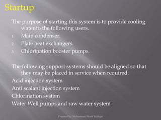
Downloaded 712 times


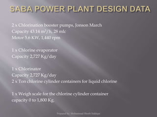


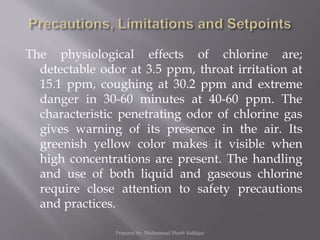

![(If a chlorine ton/cylinder container develops a leak, its contents
are disposed of by placing it in position for gas withdrawal
and bubbling the gas into the neutralization bath as describe
below.)
1.4 pounds of Caustic Soda (NaOH) is required for neutralization
of one pound of Chlorine.
3.7 pounds of Soda Ash (Na2CO3) is required for neutralization of
one pounds of Chlorine.
1.3 pond of Hydrated Lime [Ca(OH)2] is required for neutralization
of one pounds of ch
Prepared by: Mohammad Shoeb Siddiqui](https://image.slidesharecdn.com/cwsystemofsabarev-151027055056-lva1-app6891/85/Cooling-water-CW-system-68-320.jpg)
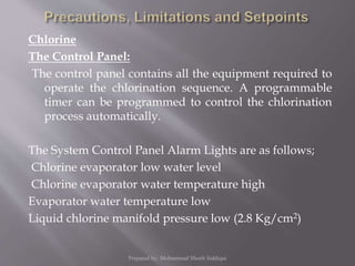
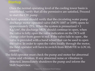


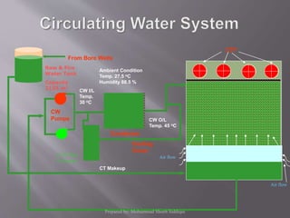
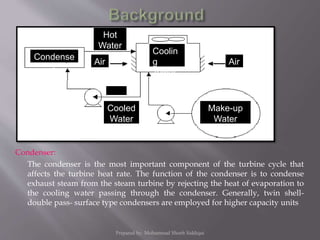
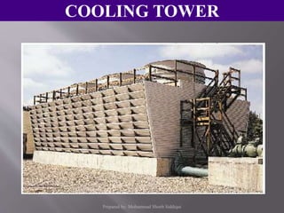
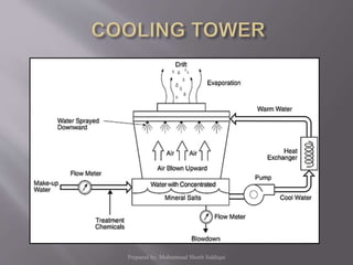
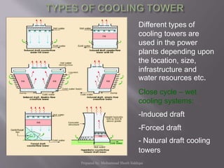
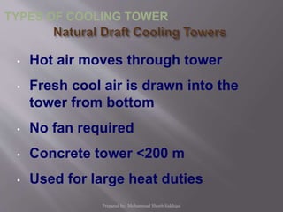
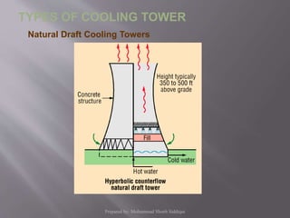
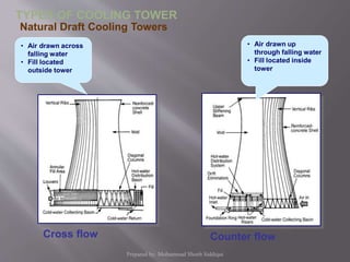
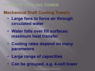
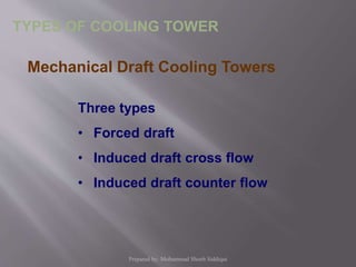
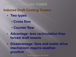
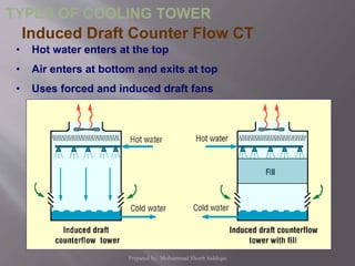
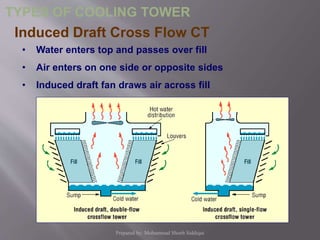
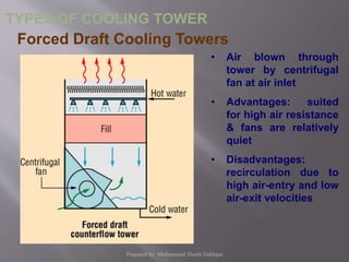
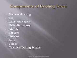
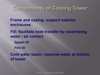
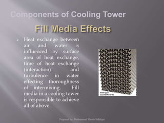
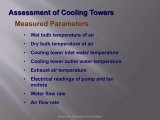
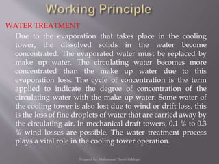
Cooling water is used to remove heat from machines and can be recycled or used once. Recirculating systems use cooling towers or ponds to remove heat. Industrial cooling towers use water sources like rivers as makeup water to replace evaporated water. They continuously circulate water through heat exchangers where heat is absorbed and rejected to the atmosphere through partial water evaporation. Different types of cooling towers exist like natural draft, induced draft, and forced draft towers which vary based on design and how air is moved through the tower. Key components, performance parameters, and maintenance factors of cooling towers are discussed.


![5G Explained! A High Level Overview [Introduction]](https://cdn.slidesharecdn.com/ss_thumbnails/5gexplainedahighleveloverview-260119165306-cc137a3e-thumbnail.jpg?width=640&height=640&fit=bounds)

