Download to read offline


![Multi-Stage Steam-Injectors for pipeline mounting
To reduce the space requirements and material usage and costs, we
have developed 2 - and 3-stage variants, which allow us to increase
the performance of the steam injectors to 3-fold. Several internal
parts are installed in only one Case and are supplied through an
outer casing pipe with steam. All previously required flanges
between the steps become no longer necessary.
The outer dimensions have been reduced to a minimum and the
result is an extremely compact device, which can be installed and
connected with little effort.
The devices are available in all sizes offered to date, but also
customized designs are possible.
Dimensions:
2-staged Execution
DN 1 (ASME) 1“ 1½“ 2“ 2½“ 3“ 4“ 5“ 6“
DN 2 (ASME) 1“ 1“/1½“ 1“/1½“ 1½“/2“ 2“ 2“/ 2½“ 3“ 3“ / 4“
L [mm] 127 170 170 257,5 318 375 400 540
H [mm] 120 130 130 150 150 200 240 250
Steam throughput at
5 bar(g) [kg/h]
240 560 560 860 1400 2000 2940 4020/5040
3-staged Execution
DN 1 (ASME) 1“ 1½“ 2“ 2½“ 3“ 4“ 5“ 6“
DN 2 (ASME) 1“ 1½“ 1½“ 2“ 2“ 2½“/3“ 3“ 5“ / 6“
L [mm] 190 255 255 385 476 560 600 810
H [mm] 120 130 130 150 150 200 240 250
Steam throughput at
5 bar(g) [kg/h]
360 840 840 1290 2100 3000 4410 6030/7560](https://image.slidesharecdn.com/steaminjectorbrochure-141203042339-conversion-gate02/85/Steam-Injector-Cataloque-5-320.jpg)
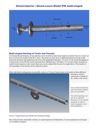


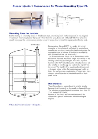
The document discusses different types of steam injectors/steam lances for heating vessels from the outside. It describes a Type IFA steam lance that can be mounted from a vessel standpipe or flange without a person entering the vessel. It also details multi-stage steam injectors that can be pipeline mounted to increase performance while reducing size and costs. Finally, it introduces a modified IFM multi-stage steam lance that can increase steam throughput and allows targeted heat distribution in a vessel with multiple injection outlets.


