1) An injector, also known as an ejector or steam injector, is a type of pump that uses the Venturi effect to pump fluids without moving parts.
2) Originally used on steam locomotives to inject boiler feedwater, injectors work by converting the pressure energy of a high-pressure motive fluid like steam into velocity energy, creating a low pressure zone that draws in and mixes with a suction fluid.
3) Modern uses of injectors include pumping chemicals into boilers, removing ash from power plant flues, producing vacuum pressure, and enhancing oil recovery processes. They are commonly used in well pumps where the jet pump is installed below ground.
This document summarizes literature on the evaluation of steam jet ejectors. It discusses their use in refrigeration, air conditioning, and other industries. Semi-empirical models are developed to design and rate ejectors, giving the entrainment ratio as a function of expansion and pressure ratios. Correlations are also developed for motive steam pressure and area ratios as functions of operating pressures and entrainment ratio. The models are based on manufacturer and experimental data and allow full ejector design based on operating conditions. Optimum operation occurs at critical conditions, and higher entrainment ratios result from lower boiler/condenser pressures and higher evaporator temperatures. Variable position nozzles and multi-ejector systems improve performance.
Ejectors use Bernoulli's principle to pump one fluid using the pressure energy of another fluid. They work by accelerating a high pressure fluid through a nozzle, lowering its pressure and increasing its velocity. This creates eddies and suction that pull in a second fluid through a side inlet. The fluids then mix and their pressure increases in a diffuser section before being discharged at an intermediate pressure between the high and low pressure fluids. Ejectors are used in oil and gas applications to compress gases.
The document discusses an ejector refrigeration system (ERS). An ERS uses an ejector instead of a compressor to increase fluid pressure without moving parts. The ejector consists of a primary nozzle, mixing chamber, ejector throat, and diffuser. High pressure fluid expands through the primary nozzle, drawing and mixing with low pressure secondary fluid in the mixing chamber. The document reviews several theories for modeling ejector performance and past studies analyzing ejector design and refrigeration cycle optimization. It also discusses design parameters like entrainment ratio and operating modes like critical and subcritical.
This document discusses the design and operation of jet ejectors. Jet ejectors use a motive fluid to pump another fluid without any moving parts. A common example is a steam jet ejector which uses steam as the motive fluid to create a vacuum. Key components are the motive nozzle, which accelerates the motive fluid, and the diffuser, which decelerates the mixed motive and suction fluids while increasing pressure. The suction fluid enters where the pressure is lowest and kinetic energy from the high-speed motive fluid is transferred to accelerate the suction fluid. In the diffuser, this kinetic energy is converted back to pressure, allowing the fluids to be discharged at a higher pressure than the suction pressure. Jet ejectors are
Steam ejector working principle
An ejector is a device used to suck the gas or vapour from the desired vessel or system. An ejector is similar to an of vacuum pump or compressor. The major difference between the ejector and the vacuum pump or compressor is it had no moving parts. Hence it is relatively low-cost and easy to operate and maintenance free equipment.
Refrigeration forms the basic essence of living comfort. Ejector Expansion Refrigeration Cycle (EERC) is a not so commonly used method of refrigeration. The use of this method is quite understated. It increases the efficiency of the normal refrigeration cycle by almost 16% over the basic cycle by utilising the energy wasted otherwise in the expansion valve in form of expansion process losses. EERC system has high potential which if harnessed properly could prove to be a very efficient method of refrigeration. This paper aims to showcase the real features of this method in a hope that it finds its way out in the commercial industry today.
Steam jet ejectors provide vacuum using high-pressure steam as the motive fluid, requiring no external power source. They have no moving parts, making them reliable and easy to maintain. Ejectors work by accelerating steam through a converging-diverging nozzle, which entrains the suction fluid and recompresses it at an intermediate pressure through a diffuser. Ejectors can be single or multi-stage, with condensers used to improve efficiency, and are well-suited for applications that require vacuum where steam is readily available such as drying and distillation.
This was one of the very first CBT modules I developed. This presentation was imported into Captivate, where additional features such as mouse-over definitions were added.
Ejector pumps have several advantages including low cost, no moving parts, and simple and compact construction. They are reliable due to their inherent simplicity and require little maintenance. Ejector pumps are also corrosion and erosion resistant, easy to install, and can achieve high vacuums as low as three microns. The selection of an ejector pump depends on factors like steam pressure, water temperature, required suction pressure and capacity. Ejector pumps are used in industries like processing, food, steel, and more for applications involving filtration, distillation, absorption, mixing, vacuum packaging, freeze drying, and degassing.
STEAM JET COOLING SYSTEM
Steam jet cooling system is a cooling technique which involves usage of steam and water for cooling purposes. In steam jet refrigeration systems, water can be used as the refrigerant. Like air, it is perfectly safe. These systems were applied successfully to refrigeration.
•Temperatures attained using water as a refrigerant are in the range which may satisfy air conditioning, cooling, or chilling requirements.
•Mostly low-grade energy and relatively small amounts of shaft work.
•This system are the utilization of mostly low-grade energy and relatively small amounts of shaft work.
•Not used when temperatures below 5°C are required.
This document discusses different types of air compressors. It describes positive displacement compressors like reciprocating compressors which work on the principle of a bicycle pump and have pistons that compress air. Rotary compressors are also positive displacement compressors that provide continuous airflow. Dynamic compressors like centrifugal compressors use a rotating impeller to transfer energy and compress incoming air without boundaries containing it. Centrifugal compressors are commonly used for medium pressure applications and produce smooth compressed air output.
The document discusses different types of compressors used to compress gases. It describes four main methods of compression: 1) trapping gas in an enclosure and reducing the volume, 2) trapping gas and compressing it by backflow before releasing it, 3) using rapidly rotating impellers to impart velocity and pressure to flowing gas, and 4) entraining gas in a high velocity jet to convert velocity to pressure. Positive displacement compressors use methods 1 and 2 through intermittent compression, while dynamic compressors use method 3 for continuous compression. Common compressor types include reciprocating, sliding vane, liquid ring, rotary lobe, helical lobe, centrifugal, and axial compressors.
Compressor and types of compressors (Thermodynamics)Hasnain Yaseen
This document provides information about different types of compressors used in thermodynamics. It discusses dynamic compressors like centrifugal and axial compressors. It also discusses positive displacement compressors like rotary, reciprocating, and scroll compressors. It describes the working principles, applications, and types of each compressor in 1-3 sentences per section. The document is an assignment on compressors for a thermodynamics lab class. It includes sections on centrifugal compressors, axial compressors, rotary compressors like screw and vane compressors, reciprocating compressors, and multi-stage centrifugal compressors.
This document provides information about air compressors, including:
- It discusses the history and principles of air compressors. Compressors increase pressure by reducing gas volume.
- Air compressors have many important applications and account for 10% of global energy use in industry. They are essential for manufacturing processes.
- Compressors are classified as either positive displacement or dynamic. Positive displacement compressors include reciprocating and rotary vane compressors.
- Multistage compression improves efficiency by compressing air in multiple stages separated by intercoolers. This reduces temperature and improves volumetric efficiency.
- Technical details are provided on reciprocating compressor operation and factors that affect volumetric efficiency.
Körting Hannover AG is a leading manufacturer of multi-stage steam jet vacuum systems that can achieve vacuums up to 10-1 mbar. These systems use steam jet ejectors in multiple stages with intermediate condensers to compress gases. Körting has been developing these systems since 1871 and their in-house testing and measurements allow them to optimize designs to minimize steam usage down to waste steam levels below 1 bar while achieving high condensing ratios up to 16:1.
Air compressors:- One of the important device used to compress air at high pressure.
The presentation contains a detailed information about air compressors, classification of air compressors, reciprocating air compressors, rotary type, multistage/ single stage compressors. advantages and lastly application/ uses of air compressors.
Hope You like the presentation.
The document outlines the objectives and methodology for a project to analyze and develop a compact vapor jet refrigeration system. The key objectives are to optimize the ejector design using single and multiple swirls, provide a full opening around the primary nozzle, analyze performance with new working fluids, design and test a 1 TR refrigeration system, and conduct experiments. The methodology involves theoretical analysis, designing and fabricating system components, flow visualization studies on the ejector, experimentation on the ejector and system, and performance analysis. The work is split into common elements and technical elements related to the ejector and system design.
This document provides an overview of compressed air systems, including:
- The types of compressors and their characteristics such as reciprocating, rotary, centrifugal, and axial compressors.
- How compressors work using principles such as the ideal gas law and Bernoulli's equation.
- Factors that affect the energy consumption of compressed air systems such as inlet air conditions, pressure settings, piping layout and leaks.
- Methods for improving efficiency such as variable speed drives, capacity control, and detailed energy audits.
The document discusses compressed air systems in detail over 5 sections, covering the scope of work, types of compressors, selection criteria, performance comparisons, and system components.
This document discusses refrigerant compressors, including their classification and types. It describes reciprocating compressors, which use pistons driven by a crankshaft to compress gases. Rotary compressors are also covered, using two meshing screws to compress gas. Centrifugal compressors rely on the kinetic energy of an impeller to increase pressure. Direct drive and belt drive compressors are compared, as well as hermetic and semi-hermetic compressors, which enclose components within a sealed shell.
An ejector refrigeration cycle powered by an internal combustion engine. it is a ppt for presentation, including introduction, working principle, performance of an ejector refrigeration.
.
This document discusses steam condensers and their types. It defines a condenser as a device that condenses steam to water using cooling water. There are two main types - jet condensers and surface condensers. Jet condensers mix steam and cooling water directly, while surface condensers separate them with a heat transfer wall. The document classifies condensers in various ways and describes the functions, elements, advantages and disadvantages of different condenser types. It also discusses vacuum creation, sources of air leaks, and the effect of condenser pressure on thermal efficiency.
This document provides an overview of reciprocating compressors. It describes how reciprocating compressors work by using pistons moving back and forth in cylinders to compress air. The document discusses the types of reciprocating compressors, how they operate through intake and compression strokes, and diagrams to illustrate the compression process. It also covers startup procedures, safety concerns around carbon buildup and explosions, efficiency calculations, and specifications for a sample reciprocating compressor.
The presentation gives a basic idea of cooling towers in big industries including the Power Plants. The performance of cooling towers and the commonenly used terms with reference to the cooling towers are also discussed at length. Care to be taken while in freezing temperatures in the European countries is also discussed.
This document provides an overview of centrifugal compressors. It begins with introductions to potential and kinetic energy as they relate to compression. It then discusses dynamic compressors like centrifugal and axial compressors. The document outlines the major parts of compressors like casings, impellers, diffusers, and seals. It also describes the cooling, lubrication, and safety systems that support compressor operation. Finally, it discusses operating characteristics, configurations like series and parallel, and performance features of compressors.
1) Reciprocating compressors work by using pistons in cylinders to reduce the volume of a gas and increase its pressure.
2) There are two main types - reciprocating compressors which use pistons in cylinders, and centrifugal compressors which use rapidly spinning impellers.
3) Reciprocating compressors can be single or double acting, and single or multi-stage for higher pressure increases. They are used when high compression ratios are required without high flow rates.
The document discusses centrifugal compressors. It begins with an introduction to air compressors in general, then describes the two main types: positive-displacement and dynamic-displacement. It focuses on centrifugal compressors, which use a rotating impeller to impart kinetic energy to air and compress it. The key components of a centrifugal compressor are the inlet, impeller, diffuser, and collector. Centrifugal compressors are commonly used in applications like gas turbines, turbochargers, pipelines, and HVAC due to benefits like fewer parts and higher efficiency compared to reciprocating compressors. However, they have a lower maximum compression ratio than reciprocating compressors.
The document summarizes a jet pump, including its history, construction, working principle, types, uses, advantages, and disadvantages. Some key points:
- Jet pumps use pressure to create suction and transport fluids without moving parts. They were first developed in 1931 but not commercialized until 1955.
- They have a nozzle that increases fluid velocity, creating suction to draw in more fluid and discharge it at higher pressure. Efficiency is typically 30-40%.
- Types include deep well, shallow well, and convertible jets. They are used for applications like oil wells and aquariums.
- Advantages include no wear, adjustability, and suitability for remote operations. Disadvantages include lower efficiency
The pdf contains explanation about the centrifugal pumps. It is usually studied by Mechanical or Civil engineering students. This pdf file will help for the students from these fields.
This document provides information about Bharat Heavy Electricals Limited (BHEL) and a summer internship completed there in the Steam Turbine Manufacturing department. It includes descriptions of:
- The basic workings of a steam turbine and how it converts thermal energy from pressurized steam into rotary motion.
- The history and development of steam turbines since ancient times.
- The main types and components of modern steam turbines, including impulse and reaction turbines.
- Details about the construction, steam flow, bearings, expansion, seals, valves, controls, and lubrication system of the specific steam turbine studied during the internship.
- An overview of the Rankine cycle that steam turbines are based on
1.) Explain what type of mechanism and application use a marine ste.pdfarbaazrabs
1.) Explain what type of mechanism and application use a marine steam engine and why?
2.) Explain the history behind a marine steam engine? and compare how it is used in today
society?
Solution
1 a)
Basic operation of a simple reciprocating steam engine
Components of steam engines
There are two fundamental components of a steam engine: the boiler or steam generator, and the
motor unit, itself often referred to as a \"steam engine.\" The two components can either be
integrated into a single unit or can be placed at a distance from each other, in a variety of
configurations.
Other components are often present; pumps (such as an injector) to supply water to the boiler
during operation, condensers to recirculate the water and recover the latent heat of vaporization,
and superheaters to raise the temperature of the steam above its saturated vapor point, and
various mechanisms to increase the draft for fireboxes. When coal is used, a chain or screw
stoking mechanism and its drive engine or motor may be included to move the fuel from a
supply bin (bunker) to the firebox.
Heat source
The heat required for boiling the water and supplying the steam can be derived from various
sources, most commonly from burning combustible materials with an appropriate supply of air in
a closed space (called variously combustion chamber, firebox). In some cases the heat source is a
nuclear reactor or geothermal energy.
Cold sink
As with all heat engines, a considerable quantity of waste heat is produced at relatively low
temperature. This must be disposed of.
The simplest cold sink is simply to vent the steam to the environment. This is often used on
Steam locomotives, but is quite inefficient. Steam locomotive condensing apparatus can be
employed to improve efficiency.
Steam turbines in power stations often use cooling towers which are essentially one form of
condenser.
Sometimes the \"waste heat\" is useful in and of itself, and in those cases very high overall
efficiency can be obtained; for example combined heat and power uses the waste heat for district
heating.
Boilers
Boilers are pressure vessels that contain water to be boiled, and some kind of mechanism for
transferring the heat to the water so as to boil it.
The two most common methods of transferring heat to the water according are:
Once turned to steam, some boilers use superheating to raise the temperature of the steam
further. This allows for greater efficiency.
Motor units
A motor unit takes a supply of steam at high pressure and temperature and gives out a supply of
steam at lower pressure and temperature, using as much of the difference in steam energy as
possible to do mechanical work.
A motor unit is often called \"steam engine\" in its own right. They will also operate on
compressed air or other gas.
Simple expansion
This means that a charge of steam works only once in the cylinder. It is then exhausted directly
into the atmosphere or into a condenser, but remaining heat can be recuperated if needed.
Hello everyone this is N Murali Mohan, working as a assistant professor in JNTUA college of engineering pulivendula, in this chapter covers the all topics, if any topics missing please inform I will correct and then upload.. thank you all
Turbines can be either impulse or reaction turbines. Impulse turbines use nozzles to direct steam onto curved blades with a bucket-like shape, extracting energy from the steam's kinetic energy. Reaction turbines have fixed and moving blades, with the fixed blades acting as nozzles to increase the steam's velocity before it passes over the moving blades. Common impulse turbines include Pelton wheels, while common reaction turbines are Francis and Kaplan turbines. Turbines are highly efficient machines that convert the energy in fluids like steam or water into useful rotational work, and they are widely used in applications like power generation, ships, aircraft, and pumps.
This document is a technical seminar report submitted by a student to fulfill requirements for a Bachelor of Technology degree in Mechanical Engineering. The report discusses the history and working principles of steam turbines, including their advantages and disadvantages. It describes different types of steam turbines such as impulse and reaction turbines. It also covers topics like compounding, steam supply and exhaust conditions, turbine components, operation principles, applications, and thermodynamics of steam turbines. The document contains detailed information presented over multiple sections and references.
This document provides an overview of radial piston pumps. It defines a radial piston pump as a type of hydraulic pump where the working pistons extend radially from a central drive shaft. The document discusses the construction, working, properties, advantages, and applications of radial piston pumps. It notes that radial piston pumps can produce smooth flow under extreme pressure and are commonly used in machine tools, hydraulic systems, and the automotive industry.
This document provides an overview of hydraulic turbines, pumps, and power plants. It discusses the main types of hydraulic turbines including Pelton, Francis, and Kaplan turbines. It describes their basic workings and classifications. It also covers centrifugal and reciprocating pumps, outlining their main components and how they function to increase liquid pressure. Finally, it mentions different types of power plants like hydroelectric, thermal, nuclear, diesel, wind, and solar that are used to generate electricity.
The document describes an experiment conducted to study the performance of a Pelton wheel turbine. The experiment varied the water discharge through the turbine while keeping the head constant. Measurements were taken of the turbine's power output and efficiency at different discharges. The results were analyzed and discussed to determine how the turbine's properties changed with discharge and if they agreed with theoretical predictions. The key components of a Pelton wheel turbine are also outlined, including the stationary nozzle, rotating buckets, and how water is directed by the nozzle onto the buckets.
The document provides an overview of the major components of a steam power plant, including:
1. The boiler, which heats water into steam, and includes accessories like air preheaters, superheaters, and economizers.
2. The steam turbine, which is spun by the steam to drive an electrical generator.
3. The condenser, which condenses the steam from the turbine.
4. The feedwater pump, which pumps water back to the boiler to repeat the steam cycle.
The document discusses a study on the manufacturing of steam turbines. It provides an outline that includes an abstract, introduction, literature review, classifications of steam turbines, results and conclusions, and references. The introduction describes steam turbines and how they work, as well as heat exchangers, pumps, and ferrous foundries which are involved in steam turbine manufacturing. It also classifies steam turbines as either impulse or reaction turbines and describes the key components of each type. The results and conclusions sections summarize the learning from an internship in steam turbine manufacturing.
The document provides information about steam turbines, including:
1. It discusses the history of steam turbines, from the first turbine designed by Hero of Alexandria in the 2nd century to modern developments in the late 19th century by engineers like de Laval and Parsons.
2. It explains the basic principles and operation of steam turbines, how steam is expanded through nozzles to impart momentum on turbine blades and rotate the shaft to generate power.
3. It covers different classifications of steam turbines such as impulse vs reaction, single stage vs multi-stage, direction of steam flow, and number of cylinders. Impulse turbines are discussed in more detail, including the basic impulse principle and types like simple, pressure comp
This document provides information about centrifugal pumps, including:
- Centrifugal pumps work by using centrifugal force to increase the pressure of a fluid. They have an impeller that spins inside a casing to impart velocity and pressure to the fluid.
- The main parts of a centrifugal pump are the impeller, casing, suction pipe, foot valve, strainer, and delivery pipe. The impeller increases the fluid's velocity and the casing converts the velocity to pressure.
- Centrifugal pumps can be used to lift fluids to high levels by imparting pressure through centrifugal force generated by the spinning impeller. Characteristic curves are used to understand a pump's performance at varying flow rates
The document discusses various types of pumps used in water supply systems including centrifugal pumps. It describes the key components of centrifugal pumps such as the casing, impeller, suction and delivery pipes. It explains how centrifugal pumps work by using centrifugal force to increase water pressure. The document also discusses other topics like selecting an appropriate pump based on factors like capacity and head, priming pumps, and appurtenances used in water distribution systems including valves, fire hydrants and water meters.
Thermodynamic Cycles for Power Generation—Brief Review
Real Steam Power Plants—General Considerations
Steam-Turbine Internal Efficiency and Expansion Lines
Closed Feed water Heaters (Surface Heaters)
The Steam Turbine
Turbine-Cycle Heat Balance and Heat and Mass Balance Diagrams
Steam-Turbine Power Plant System Performance Analysis Considerations
Second-Law Analysis of Steam-Turbine Power Plants
Gas-Turbine Power Plant Systems
Combined-Cycle Power Plant Systems
This document provides information on various types of pumps, with a focus on centrifugal pumps. It defines different types of pumps and discusses why centrifugal pumps are commonly used. It then provides details on the components and operating principles of centrifugal pumps. The document also discusses pump performance curves, cavitation, net positive suction head (NPSH), affinity laws, and best practices for pumping systems.
Turbines and recipocating pumps and miscellaneous hydraulic machinesMohit Yadav
This document provides information about various topics related to hydraulic machines covered in a fluid mechanics project. It includes 3 sections: turbines, centrifugal pumps, and reciprocating pumps. For turbines, it discusses the basic working principles and types of turbines such as Pelton, Kaplan, and Francis turbines. It provides details on the components and working of each turbine. For centrifugal pumps, it explains the working principle and components like impeller, casing, and discusses concepts such as priming. It also includes the velocity triangle and equations for work done.
1. An innovation in hydraulic turbine design is presented involving an assembly of conical wicket gates and a mixed-flow type runner with fixed blades, followed by an asymmetrical draft cone.
2. The innovation enables an extremely compact turbine design that brings significant savings in weight and reduced civil works compared to conventional Francis turbines.
3. Extensive hydraulic tests of a scale model are proposed as the next step to validate the performance of the new turbine design across a wide operating range.
1. VOLUME 1.
Injector
From Wikipedia, the free encyclopedia
"Ejector" redirects here. For other uses, see Injector (disambiguation) and Ejector (disambiguation).
Diagram of a typical modern ejector.
Exhaust Steam Injector
An injector, ejector, steam ejector, steam injector,eductor-jet pump or thermocompressor is a
type ofpump. There are two varieties of injector, non-lifting and lifting.
The non-lifting injector cold water input is fed by gravity. It uses the principle of induced current
(Impulse (physics)) to push water up to the boiler check valve. It avoids the premature boiling of feed
water at very low absolute pressure, by avoiding theVenturi effect. The steam cone minimum orifice
diameter is kept larger than the combining cone minimum diameter.[1]
The non-lifting Nathan 4000
injector used on the Southern Pacific 4294 could push 12,000 US gallons (45,000 L) per hour at 250
psi (17 bar).[2]
The lifting injector uses the Venturi effect of a converging-diverging nozzle to convert
the pressure energy of a motive fluid to velocity energy which creates a low pressure zone that
draws in and entrains a suction fluid. After passing through the throat of the injector, the mixed fluid
expands and the velocity is reduced which results in recompressing the mixed fluids by converting
velocity energy back into pressure energy. The motive fluid may be a liquid, steam or any other gas.
The entrained suction fluid may be a gas, a liquid, a slurry, or a dust-laden gas stream.[3][4]
The adjacent diagram depicts a typical modern injector. It consists of a motive fluid inlet nozzle and
a converging-diverging outlet nozzle. Water, air, steam, or any other fluid at high pressure provides
the motive force at the inlet.
The Venturi effect is a particular case of Bernoulli's principle. Fluid under high pressure is converted
into a high-velocity jet at the throat of the convergent-divergent nozzle which creates a low pressure
2. at that point. The low pressure draws the suction fluid into the convergent-divergent nozzle where it
mixes with the motive fluid.
In essence, the pressure energy of the inlet motive fluid is converted to kinetic energy in the form of
velocity head at the throat of the convergent-divergent nozzle. As the mixed fluid then expands in the
divergent diffuser, the kinetic energy is converted back to pressure energy at the diffuser outlet in
accordance with Bernoulli's principle. Steam locomotives use injectors to pump water into the steam-
producing boiler and some of the steam is used as the injector's motive fluid. Suchsteam
injectors take advantage of condensation of the motive steam resulting from the mixing with cold
feed water.
Depending on the specific application, an injector can take the form of an eductor-jet pump, a water
eductor, a vacuum ejector, a steam-jet ejector, or an aspirator.
Contents
[hide]
1Key design parameters
2History
o 2.1Feedwater injectors
2.1.1Cones
2.1.2Overflow
2.1.3Check valve
2.1.4Initial skepticism and advantages over mechanical feed pumps
2.1.5Exhaust steam injector
2.1.6Problems
o 2.2Vacuum ejectors
o 2.3Earlier application of the principle
3Modern uses
4Well pumps
5Multi-stage steam vacuum ejectors
6Construction materials
7See also
8References
9Additional reading
10External links
Key design parameters[edit]
The compression ratio of the injector, , is defined as ratio of the injector's outlet
pressure to the inlet pressure of the suction fluid .
The entrainment ratio of the injector, , is defined as the amount (in kg/h) of suction fluid
that can be entrained and compressed by a given amount (in kg/h) of motive fluid.
The compression ratio and the entrainment ratio are key parameters in designing an injector or
ejector.
History[edit]
3. A- Steam from boiler, B- Needle valve, C- Needle valve handle, D- Steam and water combine, E- Water feed,
F- Combining cone, G- Delivery nozzle and cone, H- delivery chamber and pipe, K- Check valve, L- Overflow
A more modern drawing of the injector used in steam locomotives.
Steam injector of a steam locomotive boiler.
The injector was invented by a Frenchman, Henri Giffard in 1858[5]
and patented in the United
Kingdomby Messrs Sharp Stewart & Co. of Glasgow. Motiveforce is provided at the inlet by a
suitable high-pressure fluid.
Feedwater injectors[edit]
4. The injector was originally used in the boilers ofsteam locomotives for injecting or pumping the boiler
feedwater into the boiler.
Cones[edit]
The injector consists of a body containing a series of three or more nozzles, "cones" or "tubes". The
motive steam passes through a nozzle that reduces its pressure below atmospheric and increases
the steam velocity. Fresh water is entrained by the steam jet, and both steam and water enter a
convergent "combining cone" which mixes them thoroughly so that the water condenses the steam,
releasing the latent heat of evaporation of the steam. This raises the heat of the feed water but the
mixing also imparts extra velocity to the water. The condensate mixture then enters a divergent
"delivery cone" which slows down the jet, and because of the additional energy thus imparted, builds
up the pressure to above that of the boiler.[6]
Overflow[edit]
An overflow is required for excess steam or water to discharge, especially during starting; if the
injector cannot initially overcome boiler pressure, the overflow allows the injector to continue to draw
water and steam.
Check valve[edit]
There is at least one check valve (called a "clack valve" in locomotives because of the distinctive
noise it makes [6]
) between the exit of the injector and the boiler to prevent back flow, and usually a
valve to prevent air being sucked in at the overflow.
Initial skepticism and advantages over mechanical feed pumps[edit]
After some initial skepticism resulting from the unfamiliar and superficially paradoxical mode of
operation, the injector was widely adopted as an alternative to mechanical pumps in steam-driven
locomotives. The addition of heat to the flow of water lessens the effect of the injected water in
cooling the water in the boiler compared to the case of cold water injected via a mechanical feed
pump. Most of the heat energy in the condensed steam is therefore returned to the boiler, increasing
the thermal efficiency of the process. Injectors are therefore thermally efficient; they are also simple
compared to the many moving parts in a feed pump.
Additionally, the amount of water supplied by a mechanical feed pump cannot easily be adjusted;
hence a feed pump must be able to supply the maximum demand for water, but then will overfill the
boiler at all other times, so an overflow must be installed returning the high-pressure water to the
pump's intake. If the feed pump is attached to the motion of the locomotive, it naturally provides
water at a rate proportional to the locomotive's speed, which reduces this problem but then means
the boiler cannot be refilled when stationary. Traction engines often use feed pumps and can
disconnect the motion from the road wheels, and can be seen stationary with their flywheels turning
in order to refill their boilers.[6]
Exhaust steam injector[edit]
Efficiency was further improved by the development of a multi-stage injector which is powered not by
live steam from the boiler but by exhaust steam from the cylinders, thereby making use of the
residual energy in the exhaust steam which would otherwise have gone to waste. However, an
exhaust injector also cannot work when the locomotive is stationary; later exhaust injectors could
use a supply of live steam if no exhaust steam was available.
Problems[edit]
Injectors can be troublesome under certain running conditions, when vibration caused the combined
steam and water jet to "knock off". Originally the injector had to be restarted by careful manipulation
of the steam and water controls, and the distraction caused by a malfunctioning injector was largely
responsible for the 1913 Ais Gill rail accident. Later injectors were designed to automatically restart
5. on sensing the collapse in vacuum from the steam jet, for example with a spring-loaded delivery
cone.
Another common problem occurs when the incoming water is too warm and is less effective at
condensing the steam in the combining cone. This can also occur if the metal body of the injector is
too hot, e.g. from prolonged use.
Vacuum ejectors[edit]
An additional use for the injector technology is in vacuum ejectors in continuous train braking
systems, which were made compulsory in the UK by the Regulation of Railways Act 1889. A vacuum
ejector uses steam pressure to draw air out of the vacuum pipe and reservoirs of continuous train
brake. Steam locomotives, with a ready source of steam, found ejector technology ideal with its
rugged simplicity and lack of moving parts. A steam locomotive usually has two ejectors: a large
ejector for releasing the brakes when stationary and a small ejector for maintaining the vacuum
against leaks. The small ejector is sometimes replaced by a reciprocating pump driven from
the crosshead because this is more economical of steam.
Vacuum brakes have been superseded by air brakes in modern trains, which use pumps,
as diesel and electric locomotives no longer have a suitable working fluid for vacuum ejectors.
Earlier application of the principle[edit]
Sketch of the smokebox of a steam locomotive, rotated 90 degrees. The similarity to the generic injector
diagram at the top of this article is apparent.
An empirical application of the principle was in widespread use on steam locomotives before its
formal development as the injector, in the form of the arrangement of theblastpipe and chimney in
the locomotive smokebox. The sketch on the right shows a cross section through a smokebox,
rotated 90 degrees; it can be seen that the same components are present, albeit differently named,
as in the generic diagram of an injector at the top of the article. Exhaust steam from the cylinders is
directed through a nozzle on the end of the blastpipe, to create a negative pressure inside the
smokebox and entrain the flue gases from the boiler which are then ejected via the chimney. The
effect is to increase the draught on the fire to a degree proportional to the rate of steam
consumption, so that as more steam is used, more heat is generated from the fire and steam
production is also increased. The effect was first noted by Richard Trevithick and subsequently
developed empirically by the early locomotive engineers; Stephenson's Rocket made use of it, and
this constitutes much of the reason for its notably improved performance in comparison with
contemporary machines.
Modern uses[edit]
The use of injectors (or ejectors) in various industrial applications has become quite common due to
their relative simplicity and adaptability. For example:
6. To inject chemicals into the boiler drums of small, stationary, low pressure boilers. In large, high-
pressure modern boilers, usage of injectors for chemical dosing is not possible due to their
limited outlet pressures.
In thermal power stations, they are used for the removal of the boiler bottom ash, the removal
of fly ash from the hoppers of the electrostatic precipitators used to remove that ash from the
boiler flue gas, and for drawing a vacuum pressure in steam turbine exhaust condensers.
Jet pumps have been used in boiling water nuclear reactors to circulate the coolant fluid.[7]
For use in producing a vacuum pressure in steam jet cooling systems.
For enhanced oil recovery processes in the oil & gas Industry.
For the bulk handling of grains or other granular or powdered materials.
The construction industry uses them for pumping turbid water and slurries.
Some aircraft (mostly earlier designs) use an ejector attached to the fuselage to provide vacuum
for gyroscopic instruments such as an attitude indicator.
Eductors are used in aircraft fuel systems as transfer pumps; fluid flow from an engine-mounted
mechanical pump can be delivered to a fuel tank-mounted eductor to transfer fuel from that tank.
Aspirators are vacuum pumps based on the same operating principle and are used
in laboratories to create a partial vacuum and for medical use in suction of mucus or bodily
fluids.
Water eductors are water pumps used for dredging silt and panning for gold, they're used
because they can handle the highly abrasive mixtures quite well.
To create vacuum system in vacuum distillation unit (oil refinery)
Well pumps[edit]
Main article: Water well pump
Jet pumps are commonly used to extract water from water wells. The main pump, often a centrifugal
pump, is powered and installed at ground level. Its discharge is split, with the greater part of the flow
leaving the system, while a portion of the flow is returned to the jet pump installed below ground in
the well. This recirculated part of the pumped fluid is used to power the jet. At the jet pump, the high-
energy, low-mass returned flow drives more fluid from the well, becoming a low-energy, high-mass
flow which is then piped to the inlet of the main pump.
The S type pump is useful for removing water from a well or container.
Shallow well pumps are those in which the jet assembly is attached directly to the main pump and
are limited to a depth of approximately 5-8m to preventcavitation.
Deep well pumps are those in which the jet is located at the bottom of the well. The maximum
depth for deep well pumps is determined by the inside diameter of and the velocity through the jet.
The major advantage of jet pumps for deep well installations is the ability to situate all mechanical
parts (e.g., electric/petrol motor, rotating impellers) at the ground surface for easy maintenance. The
advent of the electrical submersible pump has partly replaced the need for jet type well pumps,
except for driven point wells or surface water intakes.
7. Multi-stage steam vacuum ejectors[edit]
In practice, for suction pressure below 100 mbar absolute, more than one ejector is used, usually
with condensers between the ejector stages. Condensing of motive steam greatly improves ejector
set efficiency; both barometric and shell-and-tube surface condensers are used.
In operation a two-stage system consists of a primary high-vacuum (HV) ejector and a secondary
low-vacuum (LV) ejector. Initially the LV ejector is operated to pull vacuum down from the starting
pressure to an intermediate pressure. Once this pressure is reached, the HV ejector is then operated
in conjunction with the LV ejector to finally pull vacuum to the required pressure.
In operation a three-stage system consists of a primary booster, a secondary high-vacuum (HV)
ejector, and a tertiary low-vacuum (LV) ejector. As per the two-stage system, initially the LV ejector
is operated to pull vacuum down from the starting pressure to an intermediate pressure. Once this
pressure is reached, the HV ejector is then operated in conjunction with the LV ejector to pull
vacuum to the lower intermediate pressure. Finally the booster is operated (in conjunction with the
HV & LV ejectors) to pull vacuum to the required pressure.
Construction materials[edit]
Injectors or ejectors are made of carbon steel, stainless steel, titanium, PTFE, carbon, and other
materials.
See also[edit]
Aspirator (pump)
De Laval nozzle
Diffusion pump
Giovanni Battista Venturi
Gustaf de Laval
Nozzle
Surface condenser
Venturi effect
References[edit]
1. Jump up^ Pullen, William Wade Fitzherbert (1900). Injectors: their Theory, Construction and
Working (Second ed.). London: The Technical Publishing Company Limited. p. 51.
2. Jump up^ Anderson.- O'Day., David N. - Russell M. H. (17 July 2013). Cab-Forward Notes Southern
Pacific Railroad's Signature Locomotive (Revision 1 ed.). Sacramento, California: Gerald Rood. p. 66.
3. Jump up^ Perry, R.H. and Green, D.W. (Editors) (2007). Perry's Chemical Engineers' Handbook (8th
ed.). McGraw Hill. ISBN 0-07-142294-3.
4. Jump up^ Power, Robert B. (1993). Steam Jet Ejectors For The Process Industries (First ed.).
McGraw-Hill. ISBN 0-07-050618-3.
5. Jump up^ Strickland L. Kneass (1894). Practice and Theory of the Injector. John Wiley & Sons
(Reprinted by Kessinger Publications, 2007 ). ISBN 0-548-47587-3.
6. ^ Jump up to:a b c Goldfinch & Semmens (2000). HowSteam Locomotives Really Work. Oxford
University Press. pp. 92–97. ISBN 978-0-19-860782-3.
7. Jump up^ "Steam-assisted jet pump". General Electric. Retrieved 17 March 2011. United States
Patent 4847043 ... recirculation of a coolant in a nuclear reactor
Additional reading[edit]
8. J.B. Snell (1973). Mechanical Engineering: Railways. Arrow Books. ISBN 0-09-908170-9.
J.T. Hodgson and C.S. Lake (1954). Locomotive Management (Tenth ed.). Tothill Press.
External links[edit]
Wikimedia Commons has
media related to Feedwater
injectors.
Use of Eductor for Lifting Water
VOLUME 2.
Ejector-Thermo compressor
Ejector-Thermocompressor
An ejector is essentially a fluid-fluid pump that has no pistons, valves, rotors, or other moving parts
and works by transfer of momentum from the primary fluid (high pressure) to the secondary fluid
aspirated (low pressure).
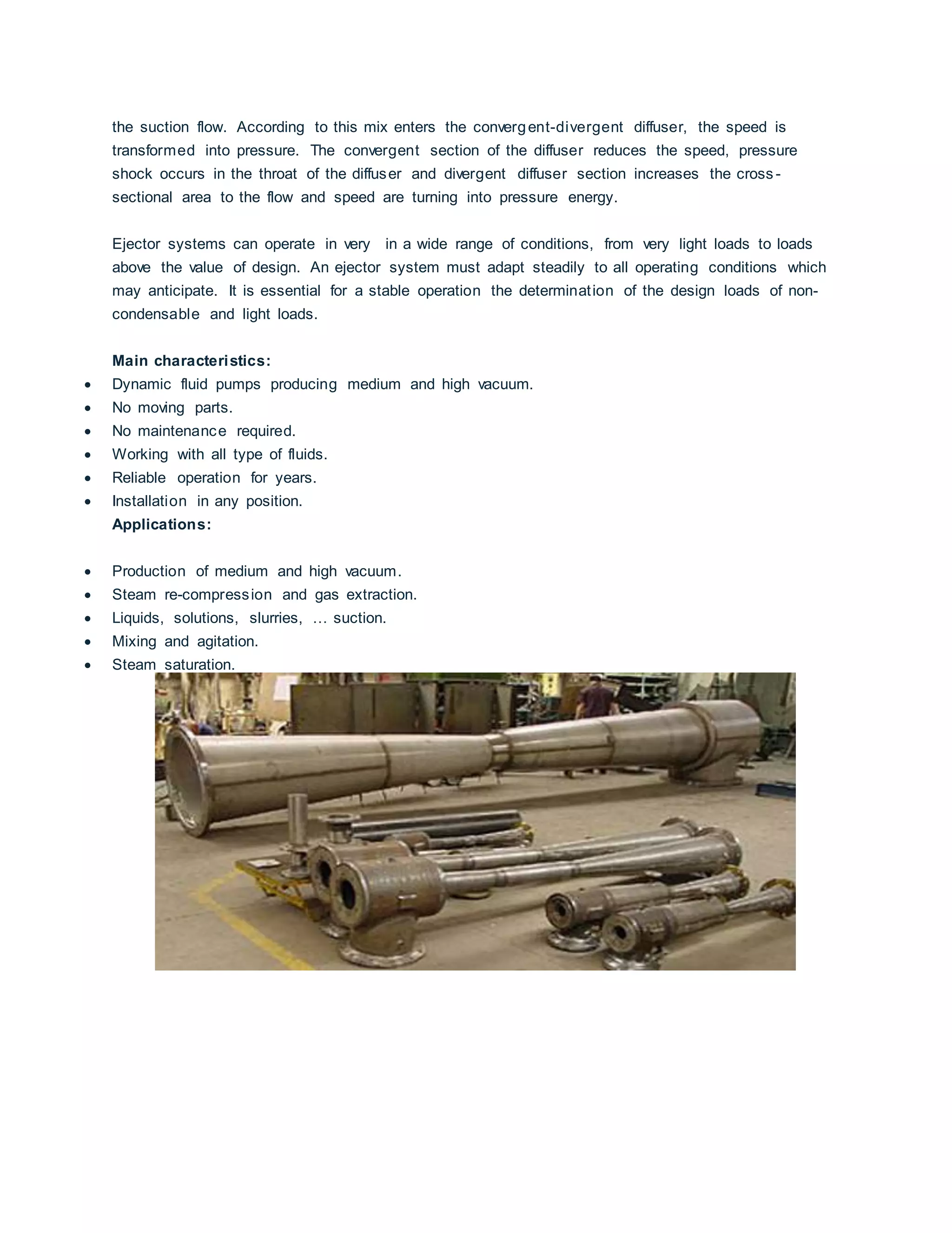
The basic operating principle of an ejector is to convert the pressure into speed. This occurs by an
adiabatic expansion of motive steam through a convergent -divergent nozzle from the motive
pressure to suction pressure. The result is a supersonic speed out of the nozzle. Usually 3 or 4
Mach speeds are reached.
In operation, the motive steam expands up to a pressure below the suction pressure. This creates
a depression that enters the suction load into the ejector. Motive steam at high speed is mixed with
9. the suction flow. According to this mix enters the convergent-divergent diffuser, the speed is
transformed into pressure. The convergent section of the diffuser reduces the speed, pressure
shock occurs in the throat of the diffuser and divergent diffuser section increases the cross -
sectional area to the flow and speed are turning into pressure energy.
Ejector systems can operate in very in a wide range of conditions, from very light loads to loads
above the value of design. An ejector system must adapt steadily to all operating conditions which
may anticipate. It is essential for a stable operation the determination of the design loads of non-
condensable and light loads.
Main characteristics:
Dynamic fluid pumps producing medium and high vacuum.
No moving parts.
No maintenance required.
Working with all type of fluids.
Reliable operation for years.
Installation in any position.
Applications:
Production of medium and high vacuum.
Steam re-compression and gas extraction.
Liquids, solutions, slurries, … suction.
Mixing and agitation.
Steam saturation.
10. Q & A > Question Details.
1. What is the purpose/function of Steam Ejector in Vacuum distillation column and how it
works?
2. Why it is placed at the top of column and why not the bottom in refinery? please explain the
barometric concept regarding this installation
DelayedCoking
Revamps
Answers
20/07/2012 A: Sudhakara Babu Marpudi, Oman RefineriesandPetroleumIndustriesCompany,
m_sudhakarababu@yahoo.com
Ejectorshave chambersthat convertpressure energyintovelocityenergy.Steam(or
motive fluid)thatactsas motive fluidisintroducedintothe chamberwithanreducer
type arrangementandfollowedimmediatelybyreducerandexpanderarrangement
(Please checkthe typical sketchof ejectors)Thisarrangementincreasesthe velocity
of motive fluidasitentersthe chamber.Asthe motive fluidexitsthe ejectorthe
emptyspace leftinthe chamberisfilledwiththe processfluid(liquid/vapor) andis
carriedout alongwiththe motive fluid.Thisisthe basicphenomenathatisknownas
the vacuum.
Locationof steamejectorsatthe top of the systemsistoensure lesserenergy
consumptionduringthe vacuumproduction.Anyvaporwill condenseinthe piping
and will buildaliquidhead inthe upstreamof ejectorsandwillneedmore energyto
create vacuum andsubsequentprocess.Unlessthere isspace createdforthe
incomingmaterial inthe downstreamof the vacuumproductionequipment,energy
costs of vacuum productionwill be expensive.The locationattopwill allow lotof
vertical space andtime for the evacuationof material drawnoutof the columns.Also
the systemundervacuumisreadyto take inair incase of any leak.Airingresscould
be dangerousforsystemswithHydrocarbon. Soitis betterthatthe areasof possible
leaks(undervacuum) toas minimumaspossible.The systeminthe downstreamof
vacuumproductionequipmentwillbe onhigherpressure sideandwill notallowair
ingressevenif itleaks.Soprobablyitisa combinationof safetyandenergy
optimisationthatgovernsthe Ejectorslocation.
26/06/2012 A: Ralph Ragsdale, Ragsdale RefiningCourses,ralph.ragsdale@att.net
The ejectors,sometimescalledeductors,alongwithanyvacuumpumpinthe
process,create the low pressure (vacuum) atthe inletof the firstejector.A headof
34 feetof water(lessathigheraltitudes) canbe usedtoremove the condensed
steamfromthe system.Normally,atthe bottomof the water column,the wateris
pumpedfroma drumas the watercolumnisheldsuspendedbythe pressure from
11. the atmosphere.Thiswatercolumndictatesthe elevationof eachcomponentof the
system.Crude vacuumunitsare designedthisway.
A watercolumnof 34 feetisnot essential forall applications,however.A vacuum
operatedglycol regenerator,forexample,mayhave simplyanoverheadcondensing
systemwithaneducatorexhaustingtothe atmosphere orflare.