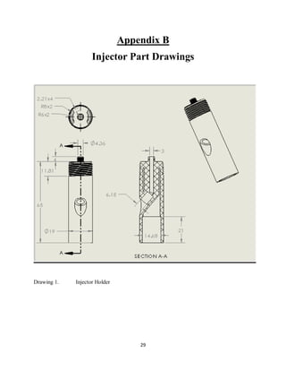
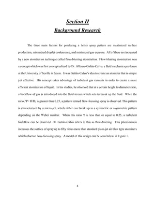
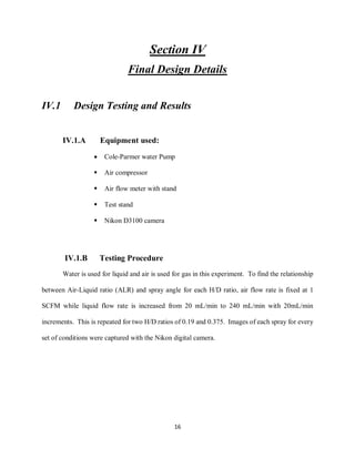
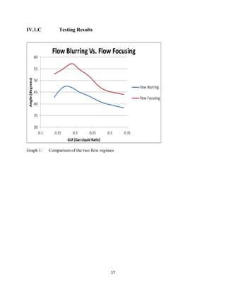
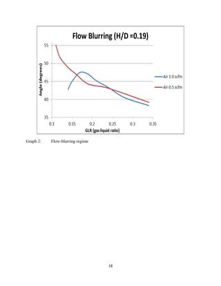
The team designed and 3D printed a fuel injector that can operate in both flow-focusing and flow-blurring regimes. Testing showed that in flow-blurring mode, higher air-liquid ratios resulted in smaller spray angles and presumed better vaporization. In flow-focusing mode, the liquid micro-jet was still visible even at higher air-liquid ratios. More precise experiments could provide insight into droplet size variations with air-liquid ratio. The design has potential application in turbine engines with some modifications.


![24
Appendix A
Relevant Equations and Sample Calculations
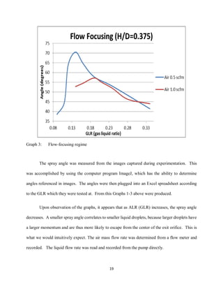
Theoretical Mass Flow Rate of Air (that could be used in later
experiments)
(Compressible Flow)
mass flow rate of air =
𝐀𝐌𝐚𝑷 𝒐√
𝒌
𝑹𝑻 𝒐
[𝟏+( 𝒌−𝟏)
𝑴𝒂 𝟐
𝟐
]
𝒌+𝟏
(𝟐(𝒌−𝟏))
A: Area of exit orifice =
𝝅
𝟒
𝑫 𝟐
units: (𝒎 𝟐
)
Ma: Mach number =
𝑽
𝑪
=
𝑽
√𝒌𝑹𝑻
units: (dimensionless)
𝑷 𝒐 : Stagnation pressure in tank units: (1kPa= 0.145 psi)
k: Specific heat ratio of air = 1.4 (dimensionless)
R : Specific gas constant of air =0.287 units: (
𝒌𝑷𝒂−𝒎 𝟑
𝒌𝒈−𝑲
)
𝑻 𝒐 = 𝒔𝒕𝒂𝒈𝒏𝒂𝒕𝒊𝒐𝒏 𝒕𝒆𝒎𝒑𝒆𝒓𝒂𝒕𝒖𝒓𝒆 𝒊𝒏 𝒕𝒂𝒏𝒌 𝒖𝒏𝒊𝒕𝒔: [( 𝑲 = 𝑭 + 𝟒𝟔𝟎𝒐
)
𝟓
𝟗
]
To find Ma,
𝑷 𝒕𝒂𝒏𝒌,𝒂𝒃𝒔
𝑷 𝒂𝒕𝒎
= [𝟏 + (
𝒌−𝟏
𝟐
) 𝑴𝒂 𝟐
](
𝒌
𝒌−𝟏
)
𝑷∗
𝑷 𝒐
=0.5283 Note: Back pressure must be
𝑷∗
𝒐𝒓 𝒍𝒆𝒔𝒔 𝒇𝒐𝒓 𝒄𝒉𝒐𝒌𝒆𝒅 𝒇𝒍𝒐𝒘. 𝑰𝒇 𝑷 𝒂𝒕𝒎 ≤ 𝑷∗
, 𝒇𝒍𝒐𝒘 𝒊𝒔 𝒄𝒉𝒐𝒌𝒆𝒅 𝒂𝒏𝒅 𝑴𝒂=1](https://image.slidesharecdn.com/01215f19-3900-4599-b54d-0b163cb2fce8-160905022428/85/Fuel-Injector-Project-27-320.jpg)