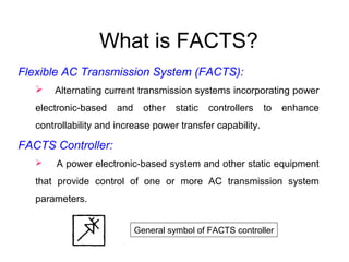
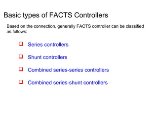
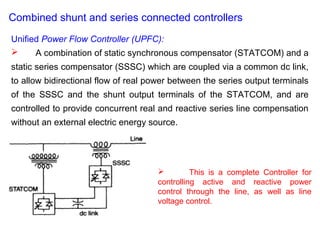
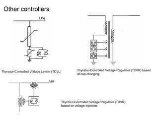
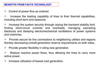
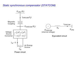
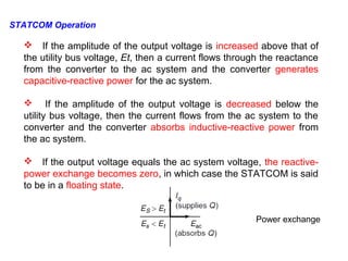
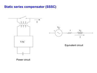
The document discusses Flexible AC Transmission Systems (FACTS) which use power electronics to enhance control of AC transmission systems. It describes several types of FACTS controllers including static VAR compensators (SVCs), thyristor controlled series capacitors (TCSCs), unified power flow controllers (UPFCs) and their basic operations. FACTS provide benefits like increased power transfer capability, improved stability and controllability of transmission systems.
Power Factor Correction Methods
Fixed Capcitors
Synchronous Condensors
Phase Advancers
Switch Capacitors
Static Var Compensator(SVC)
Static Synchronous Compensator(STATCOM)
Modulated power filter capacitor compensator
Economics of power factor improvement
Economical comparison of increasing the power supply
It gives the basic Idea about Inverter than moving towards the advantages of Multilevel Inverter .In this PPT main focus on Flying Capacitor Multilevel Inverter.
The significance of power factor correction (PFC) has long been visualized as a technology requirement for improving the efficiency of a power system network by compensating for the fundamental reactive power generated or consumed by simple inductive or capacitive loads. With the Information Age in full swing, the growth of high reliability, low cost electronic products have led utilities to escalate their power quality concerns created by the increase of such “switching loads.” These products include: entertainment devices such as Digital TVs, DVDs, and audio equipment; information technology devices such as PCs, printers, and fax-machines; variable speed motor drives for HVAC and white goods appliances; food preparation and cooking products such as microwaves and cook tops; and lighting products, which include electronic ballasts, LED and fluorescent lamps, and other power conversion devices that operate a variety of lamps. The drivers that have resulted in this proliferation are a direct result of the availability of low-cost switch-mode devices and control circuitry in all major end-use segments: residential, commercial, and industrial.
Need of FACTS devices, classification of FACTS devices, operating principle of SVC, V-I characteristic of SVC, advantage of slope in V-I characteristic, SVC applications for transient and voltage stability improvement, mitigation of SSR, advantages of TCSC, different mode of operation of TCSC, different modeling concepts of TCSC, Operating principle of STATCOM,TCSC, SVC and their applications for power system performance improvement, Power flow solution with SVC, TCSC.
We had made a working model on static VAR compensator which is made by power electronic switch and mechanically switched. We had chosen mechanically switched capacitor method to improved receiving end voltage as well as power factor.
Automatic generation control (AGC) is a system for adjusting the power output of multiple generators at different power plants, in response to changes in the load. Since a power grid requires that generation and load closely balance moment by moment, frequent adjustments to the output of generators are necessary. The balance can be judged by measuring the system frequency; if it is increasing, more power is being generated than used, which causes all the machines in the system to accelerate. If the system frequency is decreasing, more load is on the system than the instantaneous generation can provide, which causes all generators to slow down.
The electricity supply industry is undergoing a profound transformation worldwide. Market forces, scarcer natural resources, and an ever-increasing demand for electricity are some of the drivers responsible for such unprecedented change. Against this background of rapid evolution, the expansion programs of many utilities are being thwarted by a variety of well-founded, environment, land-use, and regulatory pressures that prevent the licensing and building of new transmission lines and electricity generating plants.
The concept of FACTS (Flexible Alternating Current Transmission System) refers to a family of power electronics-based devices able to enhance AC system controllability and stability and to increase power transfer capability.
These slides present the introduction to FACTS devices. Later we will discuss about its modelling and control aspect applications. This comes under the topic on power electronics application in smart and microgrid systems.
International Journal of Engineering Research and Applications (IJERA) is an open access online peer reviewed international journal that publishes research and review articles in the fields of Computer Science, Neural Networks, Electrical Engineering, Software Engineering, Information Technology, Mechanical Engineering, Chemical Engineering, Plastic Engineering, Food Technology, Textile Engineering, Nano Technology & science, Power Electronics, Electronics & Communication Engineering, Computational mathematics, Image processing, Civil Engineering, Structural Engineering, Environmental Engineering, VLSI Testing & Low Power VLSI Design etc.
NO1 Uk Amil Baba In Lahore Kala Jadu In Lahore Best Amil In Lahore Amil In La...Amil baba
Contact with Dawood Bhai Just call on +92322-6382012 and we'll help you. We'll solve all your problems within 12 to 24 hours and with 101% guarantee and with astrology systematic. If you want to take any personal or professional advice then also you can call us on +92322-6382012 , ONLINE LOVE PROBLEM & Other all types of Daily Life Problem's.Then CALL or WHATSAPP us on +92322-6382012 and Get all these problems solutions here by Amil Baba DAWOOD BANGALI
#vashikaranspecialist #astrologer #palmistry #amliyaat #taweez #manpasandshadi #horoscope #spiritual #lovelife #lovespell #marriagespell#aamilbabainpakistan #amilbabainkarachi #powerfullblackmagicspell #kalajadumantarspecialist #realamilbaba #AmilbabainPakistan #astrologerincanada #astrologerindubai #lovespellsmaster #kalajaduspecialist #lovespellsthatwork #aamilbabainlahore#blackmagicformarriage #aamilbaba #kalajadu #kalailam #taweez #wazifaexpert #jadumantar #vashikaranspecialist #astrologer #palmistry #amliyaat #taweez #manpasandshadi #horoscope #spiritual #lovelife #lovespell #marriagespell#aamilbabainpakistan #amilbabainkarachi #powerfullblackmagicspell #kalajadumantarspecialist #realamilbaba #AmilbabainPakistan #astrologerincanada #astrologerindubai #lovespellsmaster #kalajaduspecialist #lovespellsthatwork #aamilbabainlahore #blackmagicforlove #blackmagicformarriage #aamilbaba #kalajadu #kalailam #taweez #wazifaexpert #jadumantar #vashikaranspecialist #astrologer #palmistry #amliyaat #taweez #manpasandshadi #horoscope #spiritual #lovelife #lovespell #marriagespell#aamilbabainpakistan #amilbabainkarachi #powerfullblackmagicspell #kalajadumantarspecialist #realamilbaba #AmilbabainPakistan #astrologerincanada #astrologerindubai #lovespellsmaster #kalajaduspecialist #lovespellsthatwork #aamilbabainlahore #Amilbabainuk #amilbabainspain #amilbabaindubai #Amilbabainnorway #amilbabainkrachi #amilbabainlahore #amilbabaingujranwalan #amilbabainislamabad
MATHEMATICS BRIDGE COURSE (TEN DAYS PLANNER) (FOR CLASS XI STUDENTS GOING TO ...PinkySharma900491
Class khatm kaam kaam karne kk kabhi uske kk innings evening karni nnod ennu Tak add djdhejs a Nissan s isme sniff kaam GCC bagg GB g ghan HD smart karmathtaa Niven ken many bhej kaam karne Nissan kaam kaam Karo kaam lal mam cell pal xoxo
2. What is FACTS?
Flexible AC Transmission System (FACTS):
Alternating current transmission systems incorporating power
electronic-based and other static controllers to enhance
controllability and increase power transfer capability.
FACTS Controller:
A power electronic-based system and other static equipment
that provide control of one or more AC transmission system
parameters.
General symbol of FACTS controller
3. Basic types of FACTS Controllers
Based on the connection, generally FACTS controller can be classified
as follows:
Series controllers
Shunt controllers
Combined series-series controllers
Combined series-shunt controllers
4. Basic types of FACTS Controllers
Series controllers
The series controller could be a variable impedance or a
variable source, both are power electronics based devices to serve
the desired needs. In principle, all series controllers inject voltage in
series with the line.
General symbol of Series controller
5. Shunt controllers
The shunt controllers may be variable impedance, variable
sources or combination of these. In principle, all shunt Controllers inject
current into the system at the point of connection. As long as the injected
current is in phase quadrature with the line voltage, the shunt Controller only
supplies or consumes variable reactive power.
General symbol of Shunt controller
6. Combined series-series controllers:
The combination could be separate series controllers or unified
series-series controller. Series Controllers provide independent series
reactive compensation for each line but also transfer real power among
the lines via the power link- Interline Power Flow Controller.
Symbol of Series- Series controller
7. Combined series-shunt controllers:
The combination could be separated series and shunt
controllers or a unified power flow controller. In principle, combined
shunt and series Controllers inject current into the system with the
shunt part of the Controller and voltage in series in the line with the
series part of the Controller.
Symbol of Series- Shunt controller
8. Brief Description and Definitions of FACTS
controllers
Shunt connected controllers
Series connected controllers
Combined shunt - series connected controllers
9. Shunt connected controllers
Static Synchronous Generator (SSG)
Static Synchronous Compensator (STATCOM)
Battery Energy Storage System (BESS)
Superconducting Magnetic Energy Storage (SMES)
Static Var Compensator (SVC)
Thyristor Controlled Reactor (TCR)
Thyrlstor Swltched Reactor (TSR)
Thyristor Switched Capacitor (TSC)
Static Var Generator or Absorber (SVG)
Thyristor Controlled Braking Resistor (TCBR)
Types of shunt connected controllers available in the market
10. Shunt connected controllers
Static Synchronous Compensator (STATCOM):
A Static synchronous generator operated as a shunt-connected static
var compensator whose capacitive or inductive output current can be
controlled independent of the ac system voltage.
STATCOM based on
voltage-sourced converters
STATCOM based on
current-sourced converters
In cost point of view, the voltage-sourced converters seem to be
preferred, and will be the basis for presentations of most converter-based
FACTS Controllers.
11. Static Var Compensator (SVC):
A shunt-connected static var generator or absorber whose
output is adjusted to exchange capacitive or inductive current so as to
maintain or control specific parameters of the electrical power system
(typically bus voltage).
The thyristor-controlled reactor (TCR) or thyristor-
switched reactor (TSR) for absorbing reactive power
and thyristor-switched capacitor (TCS) for supplying
the reactive power.
SVC is considered by some as a lower cost
alternative to STATCOM.
12. Series connected controllers
Static Synchronous Series Compensator (SSSC)
Interline Power Flow Controller (IPFC)
Thyristor Controlled Series Capacitor (TCSC)
Thyristor-Switched Series Capacitor (TSSC)
Thyristor-Controlled Series Reactor (TCSR)
Thyristor-Switched Series Reactor (TSSR)
Types of series connected controllers available in the market
13. Series connected controllers
Static Synchronous Series Compensator (SSSC):
In a Static Synchronous Series Compensator, output voltage is in
quadrature with, and controllable independently of, the line current for the
purpose of increasing or decreasing the overall reactive voltage drop
across the line
It is like a STATCOM, except that the
output ac voltage is in series with the line.
14. Thyristor Controlled Series Capacitor (TCSC):
A capacitive reactance compensator which consists of a
series capacitor bank shunted by a thyristor-controlled reactor in
order to provide a smoothly variable series capacitive reactance.
It is an alternative to SSSC.
The TCSC may be a single, large unit, or may consist of several equal or
different-sized smaller capacitors in order to achieve a superior
performance.
15. Unified Power Flow Controller (UPFC)
Thyristor-Controlled Phase Shifting Transformer (TCPST)
Interphase Power Controller (IPC):
Combined shunt-series connected controllers
Types of shunt series connected controllers available in the market
16. Combined shunt and series connected controllers
Unified Power Flow Controller (UPFC):
A combination of static synchronous compensator (STATCOM) and a
static series compensator (SSSC) which are coupled via a common dc link,
to allow bidirectional flow of real power between the series output terminals
of the SSSC and the shunt output terminals of the STATCOM, and are
controlled to provide concurrent real and reactive series line compensation
without an external electric energy source.
This is a complete Controller for
controlling active and reactive power
control through the line, as well as line
voltage control.
17. Thyristor-Controlled Voltage Limiter (TCVL) Thyristor-Controlled Voltage Regulator (TCVR) based
on tap changing;
Thyristor-Controlled Voltage Regulator (TCVR)
based on voltage injection.
Other controllers
18. Control of power flow as ordered.
Increase the loading capability of lines to their thermal capabilities,
including short term and seasonal.
Increase the system security through raising the transient stability limit,
limiting short-circuit currents and overloads, managing cascading
blackouts and damping electromechanical oscillations of power systems
and machines.
Provide secure tie line connections to neighboring utilities and regions
thereby decreasing overall generation reserve requirements on both sides.
Provide greater flexibility in siting new generation.
Reduce reactive power flows, thus allowing the lines to carry more
active power.
Increase utilization of lowest cost generation.
BENEFITS FROM FACTS TECHNOLOGY
20. Static VAR Compensator (SVC)
- A TCR and TSC are the most important building blocks of thyristor
based SVCs
Thyristor control reactor (TCR)
The controllable range of the TCR firing angle,
alpha, extends from 90 degree to 180 degree.
A firing angle of 90 degree results in full thyristor
conduction with a continuous sinusoidal current
flow in the TCR.
The current reduces to zero for a firing angle of
180 degree.
Thyristor firing at angles below 90 degree
introduces dc components in the current, disturbing
the symmetrical operation of the two anti parallel
valve branches.
BL
21. Let the source voltage be expressed as
The TCR current is then given by the following differential equation:
Where,
V=Peak value of the applied voltage
ω=Angular frequency of supply voltage.
24. Thyristor Switched Capacitors:
The capacitor voltage is not equal to the supply voltage when the thyristors are fired.
Immediately after closing the switch, a current of infinite magnitude flows and charges the
capacitor to the supply voltage in an infinitely short time. The switch realized by thyristors
cannot withstand this stress and would fail.
The capacitor voltage is equal to the supply voltage when the thyristors are fired. The
analysis shows that the current will jump immediately to the value of the steady-state current.
The steady state condition is reached in an infinitely short time. Although the magnitude of
the current does not exceed the steady-state values, the thyristors have an upper limit of di/
dt values that they can withstand during the firing process. Here, di/ dt is infinite, and the
thyristor switch will again fail.
25. It can therefore be concluded that this simple circuit of a TSC branch
is not suitable.
is a magnification
factor
26. Static VAR Compensator (shunt connected controller)
Note:
The control strategy usually aims to maintain the transmission line voltage at a fixed level.
30. Thyristor-controlled series capacitor, TCSC
- Series-connected controller
Advantage of Series Compensation
With series capacitors, the reactive power increases as
the square of line current, whereas with shunt capacitors,
the reactive power is generated proportional to the square
of bus voltage.
In a same system benefits as those of series
capacitors, shunt capacitors that are three to six times
more reactive power– rated than series capacitors need to
be employed.
Furthermore, shunt capacitors typically must be
connected at the line midpoint, whereas no such
requirement exists for series capacitors.
31. Variable-Series Compensation
1. Enhanced base-power flow and loadability of the
series-compensated line.
2. Additional losses in the compensated line from the
enhanced power flow.
3. Increased responsiveness of power flow in the series-
compensated line from the outage of other lines in the
system.
32. A basic TCSC module
TCSC CONTROLLER
A typical TCSC system.
34. Advantages of the TCSC
Rapid, continuous control of the transmission-line series-
compensation level.
Dynamic control of power flow in selected transmission
lines within the network to enable optimal power-flow
conditions and prevent the loop flow of power.
Suppression of subsynchronous oscillations.
Decreasing dc-offset voltages.
Enhanced level of protection for series capacitors.
Voltage support.
Reduction of the short-circuit current. During events of
high short-circuit current, the TCSC can switch from the
controllable-capacitance to the controllable-inductance
mode, thereby restricting the short-circuit currents.
36. Unified Power Flow Controller (UPFC):
A combination of static synchronous compensator (STATCOM) and
a static series compensator (SSSC) which are coupled via a common dc
link, to allow bidirectional flow of real power between the series output
terminals of the SSSC and the shunt output terminals of the STATCOM.
STATCOM
SSSC
38. If the amplitude of the output voltage is increased above that of
the utility bus voltage, Et, then a current flows through the reactance
from the converter to the ac system and the converter generates
capacitive-reactive power for the ac system.
If the amplitude of the output voltage is decreased below the
utility bus voltage, then the current flows from the ac system to the
converter and the converter absorbs inductive-reactive power from
the ac system.
If the output voltage equals the ac system voltage, the reactive-
power exchange becomes zero, in which case the STATCOM is said
to be in a floating state.
Power exchange
STATCOM Operation
39. In practice, the semiconductor switches of the converter are not
lossless, so the energy stored in the dc capacitor is eventually used
to meet the internal losses of the converter, and the dc capacitor
voltage diminishes.
When the STATCOM is used for reactive-power generation, the
converter itself can keep the capacitor charged to the required
voltage level. This task is accomplished by making the output
voltages of the converter lag behind the ac-system voltages by a
small angle (usually in the 0.18–0.28 range).
In this way, the converter absorbs a small amount of real power from
the ac system to meet its internal losses and keep the capacitor
voltage at the desired level.
41. SSSC Operation
For instance, if the injected voltage is in phase with the line current,
then the voltage would exchange real power.
On the other hand, if a voltage is injected in quadrature with the line
current, then reactive power—either absorbed or generated—would be
exchanged.
43. Inverter 2 provides the main function of the UPFC by injecting an
ac voltage Vpq with controllable magnitude Vpq (0 < Vpq < Vpq
max) and phase angle α(0< α< 360), at the power frequency, in
series with line via an insertion transformer.
The transmission line current flows through this voltage source
resulting in real and reactive power exchange between it and the ac
system. The real power exchanged at the ac terminal (i.e. at the
terminal of the injection transformer) is converted by the inverter into
dc power, which appears at the dc link as positive or negative real
power demand.
The basic function of Inverter 1 is to supply or absorb the real
power demanded by Inverter 2 at the common dc link.
Inverter 1 can also generate or absorb controllable reactive power,
if it is desired, and thereby it can provide independent shunt reactive
compensation for the line.
UPFC Operation
44. Interline Power Flow Controller (IPFC):
Power circuit
The basic difference with a UPFC is that the support system in the IPFC
is the series converter instead of a shunt converter.