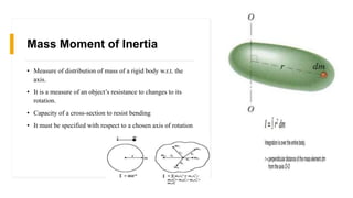
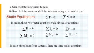
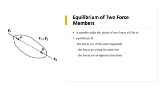
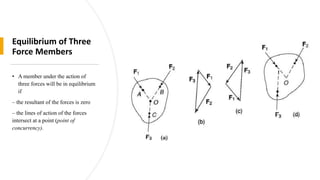
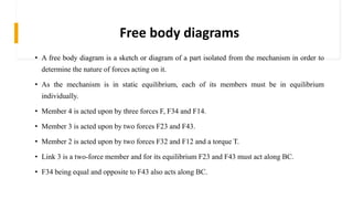
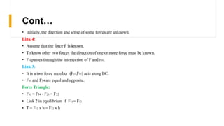
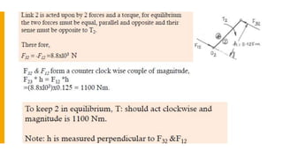
Download to read offline


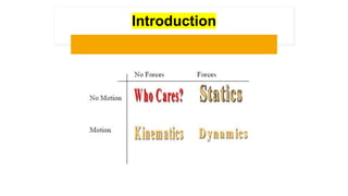
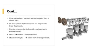
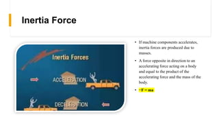
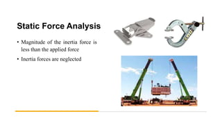
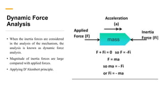
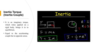
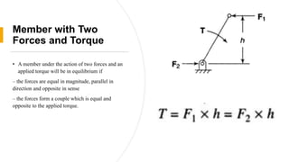
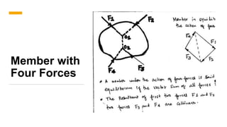
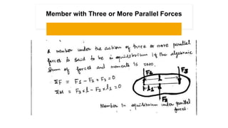
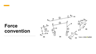


This document provides an overview of static force analysis in machinery dynamics. It introduces key concepts like inertia force, inertia torque, and static versus dynamic force analysis. The document explains that static force analysis neglects inertia forces, while dynamic analysis considers them. It also covers topics like mass moment of inertia, equilibrium conditions for members under different force configurations, and using free body diagrams to determine unknown forces on machine components. The goal of static force analysis is to determine the forces in a mechanism when it is at rest.